-
Philips PM 6667 Frequency Counter
Posted by
xrunner
on 04 May, 2015 22:04
-
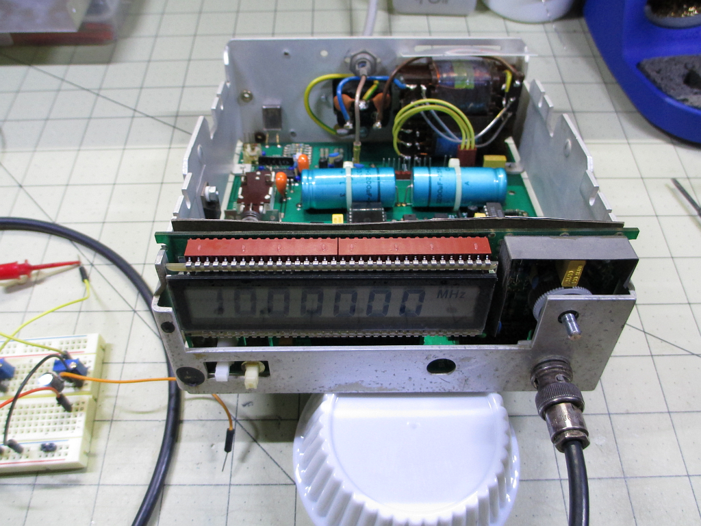
Got this little guy off Ebay. Plan to clean/restore it. It appears to be circa '79/'80, and has an Intel 8048 microcontroller (one of Intel's first). I did find the manual online. Will post more pics soon. Says "Made in Sweden" on the back plate.

At the moment it smells highly of nicotine ...


-
-
Interesting to read that Philips has "Made in Sweden" gear

More typical is "Made in Belgium" or "Made in Holland".
Cool restoration project!
The Philips PE 1542 power supply is Made in Belgium.
That's another cool restoration project. Maybe your next!
-
#2 Reply
Posted by
Shock
on 04 May, 2015 22:11
-
Some of the high resolution digits appeared to have fallen off the right hand side of the display.
-
#3 Reply
Posted by
xrunner
on 04 May, 2015 22:27
-
Some of the high resolution digits appeared to have fallen off the right hand side of the display.
LOL - that's what I thought! But it says so, so it must be true.

Here's one more for today. I don't know what the green flowery sticker means.

-
-
I have two of these great counters.
One is in brown / dark housing and one is in a grey housing
I do not recall, where they are made, will have a look tomorrow.
Most astonishing fact is the accuracy after so many years.
-
#5 Reply
Posted by
xrunner
on 04 May, 2015 23:09
-
I have two of these great counters.
One is in brown / dark housing and one is in a grey housing
This one is grey, with a light coating of cigarette smoke.

I do not recall, where they are made, will have a look tomorrow.
Most astonishing fact is the accuracy after so many years.
Well, this one is certainly accurate to less then 100 Hz at 100 MHz, but of course those digits are not available. However I will also check it at 10 MHz and less.
-
#6 Reply
Posted by
edavid
on 05 May, 2015 00:03
-
Some of the high resolution digits appeared to have fallen off the right hand side of the display.
In this case, "high resolution" is marketing-speak for a reciprocal counter.
-
#7 Reply
Posted by
Vgkid
on 05 May, 2015 01:16
-
Cute little counter.
-
#8 Reply
Posted by
dom0
on 05 May, 2015 07:52
-
Interesting to read that Philips has "Made in Sweden" gear
More typical is "Made in Belgium" or "Made in Holland".
Philips made T&M stuff in Belgium, Holland, Sweden and Germany as far as I know.
Most generators (entire PM513x series, PM519x series etc) were made in Germany, counters were made in Sweden (probably why Pendulum is Swedish, too), scopes were Holland.
-
-
Both of my PM6667 counters are made in Sweden.
Interestingly, I never noticed that before.
Here are some pictures of both counters, hooked up to a 1 MHz sine signal.
-
#10 Reply
Posted by
EEVblog
on 05 May, 2015 09:32
-
The PM6666 is an excellent little counter/time to put on your watch list, probably the best of those small Philips counters. Hard to find them with an oven option though.
-
#11 Reply
Posted by
dom0
on 05 May, 2015 09:36
-
Many of the PM6666 around have the GPIB option not installed, too. (Which is a "don't care", depending on what it is for). The PM6654 might be interesting, too. It's essentially the larger and faster lab version.
-
-
There is also a PM6669, also small and reliable.
But I also think the PM6666 was by far the best one.
Just make sure to exchange the mains power connector, if it has the line filter installed.
They like to let the magic smoke out and even get on fire.
I have exchanged them on all my Philips counters.
-
#13 Reply
Posted by
dom0
on 05 May, 2015 10:33
-
Oh and the little cutie, I'm not sure about the number, I think it was PM6661. Not even reciprocal I think.
/e: Yes, Google image search confirms "PM6661" = "cutie".
-
#14 Reply
Posted by
xrunner
on 05 May, 2015 11:55
-
Both of my PM6667 counters are made in Sweden.
Interestingly, I never noticed that before.
Here are some pictures of both counters, hooked up to a 1 MHz sine signal.
HV,
I noticed yours have a little test point (?) for the 10 MHz ref. Is that what it is near the bottom, or is it a screw adjustment? Mine does not have that, must have been added to later models.

-
-
Hello xrunner,
Yes, both of them have this little output pin as a testpoint.
It looks like a screw but it is not.
Here are some closeup pictures from the outside and the inside of this pin.
Just for fun, I hooked up my Agilent counter to this pin.
See results in the picture.
Not bad for a low cost counter from 1986 (Based on date codes on chips)
-
#16 Reply
Posted by
G0HZU
on 05 May, 2015 14:10
-
For anyone thinking of buying a counter like this: IMO the PM6667 is a bargain basement 7 digit reciprocal counter that is very slow. Probably best suited for looking at divided down digital clock signals where its reciprocal operation will be useful at very low input frequencies. It would be a PITA to use even for basic for ham/CB radio alignment because of the slow update rate and limited resolution.
Note: I have an old PM6669 universal counter here and it is a similar size and is a much better counter than the 6667. It's a universal counter with more features, faster display and 9 digits instead of 7. It's only an inch wider than the PM6667 and maybe 2 inches deeper on a shelf.
But I don't rate either of the 6669 or 6667 as a good choice as a first counter as they both have a gloomy LCD display and the standard timebase oscillator performance is quite poor on both of them. The MTCXO option doesn't offer very good performance so to get the best from the PM6669 you need to feed it an external reference. I don't think you can get an oven option on any of these counters. The triggering/stability performance on noisy signals is probably average. You also have the exploding mains inlet filter issue to worry about. There are better choices out there.
-
#17 Reply
Posted by
G0HZU
on 05 May, 2015 14:44
-
I had a look on ebay and the prices for the PM6666,7,8,9 counters seem very high. Even for the PM6667.
I paid something like £85 for my (very scruffy) 1.3GHz PM6669 about 20 years ago and although this was a huge bargain back then I wouldn't think these counters are worth more than £150 today even for a tidy example. But some ebay auctions are asking £700 which seems a tad optimistic to me...
-
#18 Reply
Posted by
G0HZU
on 05 May, 2015 15:21
-
Just for fun, I hooked up my Agilent counter to this pin.
See results in the picture.
Not bad for a low cost counter from 1986 (Based on date codes on chips)
My 6669 probably has a similar circuit for the standard timebase oscillator although it sits on a little plug in PCB in the 6669.
I can't remember when I last tried to adjust the 6669 but it's warmup drift performance isn't that good.
Usually it starts off reading about +10Hz high (if fed an accurate 10MHz signal) and over about an hour it drifts down to maybe -5Hz and depending on the ambient temparature it usually ends up within a few Hz of 10MHz. But a lot depends on the temperature in the room.
The outer case of the PM6669 counter has to be removed when adjusting the (standard) reference as it has a variable capacitor next to the crystal and this is deep inside the counter. I never liked doing this because the frequency shifts slightly as soon as the outer cover is removed so it demands an iterative and very fiddly/slow approach to adjust it with any precision.
-
#19 Reply
Posted by
gfiber
on 05 May, 2015 15:24
-
I have the PM6676 1.5 GHz version, would like to have a High Stability time base oven for it. Right now it is connected to my Trimble Thunderbolt, but the Timebase oven would make it more portable too.
-
#20 Reply
Posted by
switcher
on 05 May, 2015 15:25
-
I've never been keen on bench instruments with LCD displays, their visibility is very dependent on prevailing light, and I think the OP's pic demonstrates this.
-
-
It always depends on the application.
I have some usage for these old and simple Philips counters for sensor testing were I only need 3 digits, then they are very handy.
There still seems to be a good market for Philips test and measurement instruments and I am also a little surprised about the relative high prices. But then, they are usually easily repaired and work stable.
These two PM6667 are now almost 30 years old and still work good.
I am not sure that my Agilent 53220A will last 30 years, I have my doubt.
-
#22 Reply
Posted by
G0HZU
on 05 May, 2015 16:25
-
But then, they are usually easily repaired and work stable.
There's certainly a lot to be said for the benefits of stable operation. In my youth I used to repair lots of ham/CB gear and it isn't always easy to get a stable reading from some makes/models of counter when probing a low level signal inside a radio. Back in those days I had access to many models of counter and the best of the lot was my old Marconi TF2430 which probably dates back the the early 1970s. It isn't a reciprocal counter but this is to its advantage in terms of radio servicing IMO.
Like your 6667 it only has a 7 digit display but it gives the most stable display of any counter I have ever used. This is all the more remarkable for it having no user controls for input level or triggering/filtering.
I still have it here today and there is no other counter on the planet I would rather use if I had to align a typical CB/HF ham radio today. Brilliant, clear LED display, very little drift in the standard oscillator and a really simple user interface. They need to be treated with some sympathy however as the thermal management of these counters is poor. So it has to be placed somewhere cool and also propped up to allow the lower vents to breathe. Otherwise the regulator at the back gets very hot and this is a common point of failure.
The standard oscillator inside is also much better than the one in my Philips PM6669. Much less drift during warmup and much more stable once warm. It could normally be used straight away as long as the room temperature was 'comfy' as it was rarely more than 7Hz away from 10MHz and usually got within 1-2Hz after a short warmup.
The only user controls on it are the three pushbuttons for gate time/resolution.
i.e. 10Hz or 1Hz or 0.1Hz resolution can be preset. It can display to 10Hz several times a second or to 1Hz in 1 second or to 0.1Hz in 10 seconds. Obviously, it often overflows the display when this happens but it still displays the lower 7 digits and it can do this up to 150MHz (despite only being branded as an 80MHz counter)
-
#23 Reply
Posted by
dom0
on 05 May, 2015 16:32
-
I never liked doing this because the frequency shifts slightly as soon as the outer cover is removed so it demands an iterative and very fiddly/slow approach to adjust it with any precision.
Reminds of adjusting a PM519x generator. You open the case and the offsets jump around 20-40 mV (easily). The manual for those generators even mentions an adjustment kit, consisting of covers with holes for all the adjustments (about two dozen), so you don't disturb the "thermal equilibrium" of all the discrete amplifier stages. What a PITA. It took me ten tries or so until I got the DC offset below +- 3 mV.
-
#24 Reply
Posted by
dom0
on 05 May, 2015 16:35
-
Like your 6667 it only has a 7 digit display but it gives the most stable display of any counter I have ever used. This is all the more remarkable for it having no user controls for input level or triggering/filtering.
I remember that someone linked me a circuit a while ago that was developed in the GDR in the mid 80s or so, a discrete input stage for a frequency counter. The System D of it was an automatic regulation of hysteresis (and I think amplification in some way) to achieve a stable 50:50 duty cycle at the output. Settled for a different circuit in the end, but that one would probably given equally good or better results (at a higher parts count, though).
-
#25 Reply
Posted by
xrunner
on 05 May, 2015 22:38
-
-
#26 Reply
Posted by
dom0
on 06 May, 2015 07:56
-
It has a rather weird mechanical design.
Trademark of Philips :-)
That rotary switch looks to me like it's made by EBE. Series probably
EBE SB 20 F.
-
#27 Reply
Posted by
xrunner
on 06 May, 2015 12:08
-
Trademark of Philips :-)
I see.
Not sure why they socketed the regulator. I mean how many times would it need to be taken apart? Why not just have the repair person unscrew it from the heat sink if need be and let it go with the main board?
Anyway - it back together and working. I looked at the schematic and found where to measure it's timebase signal, and it read 9,999,954 Hz, which of course is 46 Hz low, and this is consistant with the main reading of 10,000,04 which I got when measuring my 10 MHz OCXO. However it's now been adjusted.
All I need to do now is clean the outer case in warm soapy water to remove the nicotine and deal with the front panel. The front panel doesn't really stay on, and the only means of it ever staying on by design was the black sticky whatever-it-is stuff you see in the pic. Well, that stuff is no good anymore. What I might do is just take it all off and replace with strategically placed double sided tape. I don't want to leave a bunch of old black smoke-laden stuff stuck to the back like that.

-
#28 Reply
Posted by
xrunner
on 07 May, 2015 00:25
-
Worked on getting the "black stuff" off the back of the panel today. It was not fun. It was some kind of black paper - not foam tape. Almost like a kind of tar paper. It was awful. I used goo gone and a razor blade. But I got it all off. I got it all cleaned up and then used some double sided tape to re-attach it.


-
-
Nice, I had 3 Philips Oscilloscopes, they all were super accurate, and probably were made in the 70's I think.
A PM3226 and a PM3217, both were super accurate scopes, loved the way they operated.
These ones were built when philips pretty much manufactured all the components inside, pretty much everything was labeled Philips in the PM3226, and it was made in India.
-
#30 Reply
Posted by
xrunner
on 07 May, 2015 13:06
-
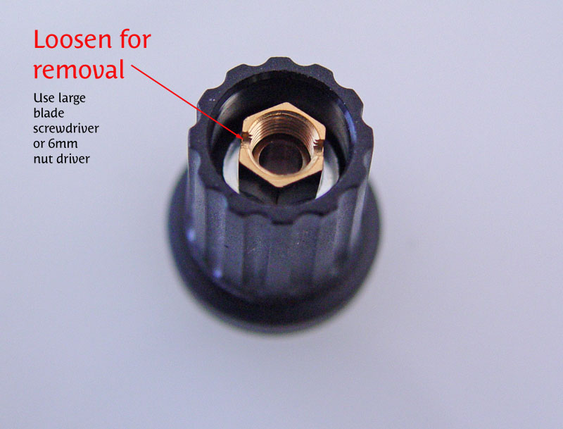
Putting it back together the sensitivity knob was very loose. I had lightly cleaned some corrosion of the shaft with 600 grit paper so I thought I made a mistake doing that, but it wasn't that. Again this is a part I've never come across. The knob actually was an adjustable fit sort of thing. The inner green part can be screwed in to a variety of positions, and the more you screw it in the harder it grips. No set screw.

-
#31 Reply
Posted by
dom0
on 07 May, 2015 13:10
-
That's a collet. Philips used them for most rotary knobs on their gear, they have a few advantages over simple set screws (no wearing down the shaft, excellent concentricity, no slipping), but are way more expensive. If you fumble off the brown knob cover there'll be a metric nut used to tighten it.
(Note: mechanical terms translated with dictionary, may or may not be the correct wors in English)
-
#32 Reply
Posted by
ebastler
on 07 May, 2015 14:45
-
That's a collet. Philips used them for most rotary knobs on their gear, they have a few advantages over simple set screws (no wearing down the shaft, excellent concentricity, no slipping), but are way more expensive. If you fumble off the brown knob cover there'll be a metric nut used to tighten it.
But be careful with that brown cap on the knob -- the plastic can get very brittle with age. With the cap being in a very visible position, breaking it causes an annoying cosmetic blemish. I managed to do that on an old Philips function generator a while ago; still need to look whether any new knobs & caps with the same dimensions are still available ...
-
#33 Reply
Posted by
xrunner
on 07 May, 2015 15:08
-
That's a collet. Philips used them for most rotary knobs on their gear, they have a few advantages over simple set screws (no wearing down the shaft, excellent concentricity, no slipping), but are way more expensive. If you fumble off the brown knob cover there'll be a metric nut used to tighten it.
Aha! Thanks - that's why I post pics of things I haven't seen before. Good info.
But be careful with that brown cap on the knob -- the plastic can get very brittle with age. With the cap being in a very visible position, breaking it causes an annoying cosmetic blemish. I managed to do that on an old Philips function generator a while ago; still need to look whether any new knobs & caps with the same dimensions are still available ...
Yes, I did attempt to push the cap off from inside but it indeed showed signs of starting to break so I chickened out. However I worked the tightening from the other end and it will be OK for now - it turns the switch OK without slipping.
-
#34 Reply
Posted by
SeanB
on 07 May, 2015 17:52
-
After 20 odd years that cap and the knob will be pretty close to welded together. freezer spray or an overnight in the freezer, then try with a flat ended drift and it might pop loose. Otherwise gentle work around the join with a stanley knife blade will often loosen this grip.


