First of all, let me say THANK YOU, you are the only one actually trying to think stuff through on the Lewin side, and I really appreciate that!
You have nothing else but to resort to the "Moral High Ground Fallacy". On the other hand, the KVL side has provided theoretical results and experimental results that perfectly agree with each other. What have you provide? Just a big pile of steaming BS.
If both your theory and experiments depend on each other, that'll do you no good.
Because the experimental data presented here was obtained by more or less blindly poking around circuits with a volt meter, and without any understanding of what is actually going on. So the measurements taken do not support in any form the claim that "KVL holds".
I didn't subtract, I measured.
[...]
I didn't make up any framework. I just used my volt meter, resistors, and transformers to find out what observable reality is.
[...]
My level-1 "framework" is what I observe. Above that I do my best to understand what's going on at a theoretical level. Maxwell, Faraday, and Kirchhoff described it elegantly. I have no problem with any of them.
So, what Jesse does is poking around a circuit with a volt meter without having an idea what it's going to show, and as he sees the measurements he makes up some explanations but doesn't validate them against established science.
Naturally, I object to what I describe as your mischaracterization of my understanding.
In fact he doesn't understand Maxwell-Faraday beyond the level of "volts per turn"
Not true, while I don't understand at the level of Dr. McDonald or Dr. Belcher, I do understand more than just "volts per turn."
As I have repeated so many times, my argument is that a closed-magnetic-circuit-core transformer secondary MODELS AND MEASURES
as if "volts per turn" is sufficient to describe it as a 2 terminal element for the sake of KVL.
But I've also always invited you to explain why you think KVL is not holding even though it measures like it is.
and especially doesn't understand that the equation describes a relation between the magnetic flux in the core and an (rotational, non-conservative) electric field around the core that is extending to infinity,
Explain this some more please. If it is non conservative and extends to infinity, then I can detect it from 1ft away, with no part of my measuring apparatus closer than 1 foot from the toroid under test?
Or do you mean I have to run a wire THROUGH the core to detect this electric field?
this being the reason why there cannot be an "inside" or "outside" of a transformer as he understands it. He doesn't realize it is this electric field that is separating charges in a path of conductor and causing "voltage" and that one needs to consider paths through this electric field to see if a loop of wire is a "transformer secondary" or not. Thus all the conclusions he derives from his observation are worthless.
Oh come on LOL Worthless?

It sounds like you're basically saying that we cannot use the secondary winding of a transformer as a 2 terminal element in a KVL loop with other elements because some of those other elements may be subject to the electric field produced by the transformer and may have voltages induced in them?
I hope not because that's absurd. There is no non-conservative field OUTSIDE a toroid for paths that do not go through the hole: Thus, if there is only one path through the hole in the toroid, and it's the secondary winding, and none of the other parts of the other elements go through the hole in the toroid, then all the other elements are not in a non-conservative field.
And by the way, I asked you several times and you never answered, but I'd still like to know if you think the following transformer core design sends out an E-Field into space, and if so, what if we wrapped it in a superconductor enclosure:

But anyway, Snedri already admitted that V2 in the below diagram would be suitable for a KVL loop, and he also admitted that V1 and V2 will have the exact same voltage:
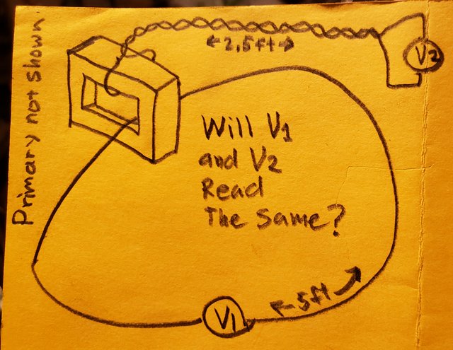
Allow me to elaborate. Below picture shows the problem I gave Jesse to evaluate. It is a toroidal core with "1V of EMF per turn". A ring of resistors is around the core. One has double the value of the other. Volt meters are connected as shown and all numbers were provided by him. I have only added one additional volt meter showing "2/3V" to demonstrate my point. I've tried visualizing the electric field component with green arrows. RED loops are "hot", voltage is induced (1V). BLUE loops are "cold", no voltage is induced. I took over Jesses notation of a "signed voltage" which here means "phase", because obviously this is all AC and there is no "sign" on a RMS volt meter. But I guess he measured with an oscilloscope and found that the voltage is "inverted" in relation to the voltage across the other resistor.
Yes, I used a scope to determine the phase. This convention was started by Lewin who also used scopes and said "At a given instant in time, ......." so I do the same. At a given instant in time, these are the voltages. A moment before or a moment later, they won't be. But at this instant in time, they are.
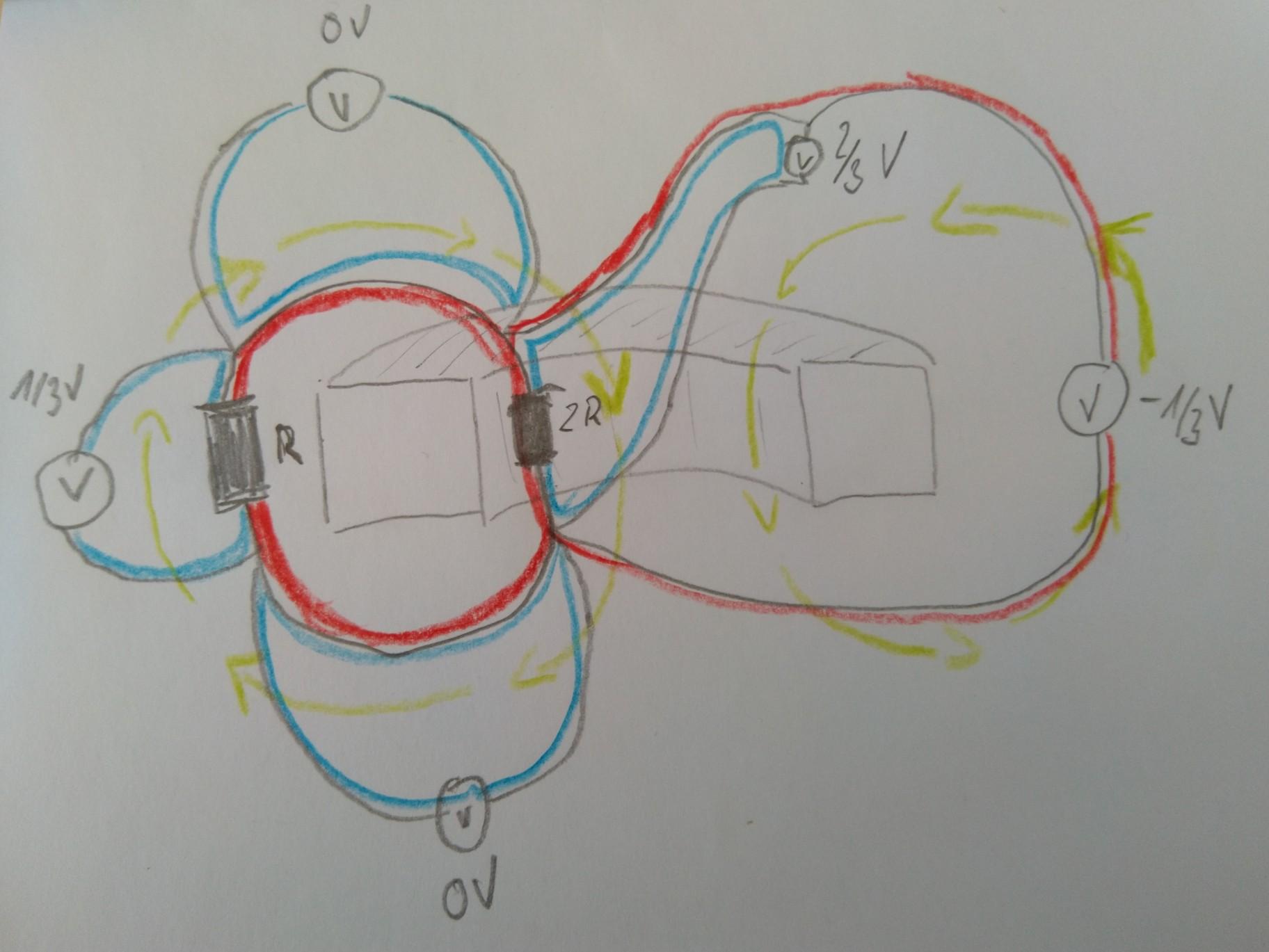
Now, to see why the blue loops are indeed cold one needs to know a tiny bit of vector calculus, or just accept the fact that all electric field components along any of the blue loops sum up to zero, in other words:
$${\oint{\mathrm{E}\;\mathrm{d}l} = 0}$$
That looks familiar.
With this in mind it should be easily visible why the red loops are "hot", because the electric field components do not sum up to zero:
$$\oint{\mathrm{E}\;\mathrm{d}l} = -\frac{\mathrm{d}B}{\mathrm{d}t},\; (\mathrm{= EMF = 1V})$$
This should also look familiar.
Just because a claim is hard to prove doesn't mean it's false.
In this case, just because a certain loop is hard to probe, it doesn't mean KVL doesn't hold.
Your probing method inherently subtracts induced voltage from your reading, leaving you with only the ohmic losses.
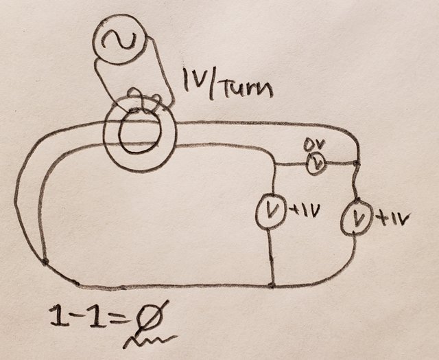
For example in the below diagram, stretch out the wires so the 3 volt meters are a million miles from the toroid. Two of the meters read 1v and the third still reads zero. It's not because there are zero volts induced, it's because there is one volt induced on each secondary and the difference between 1 and 1 is zero.
You are, buy definition, only measuring ohmic losses, because you are using a method of measuring which specifically subtracts all induced voltage differences.
And besides, KVL specifically requires that all elements have EXACTLY 2 terminals -- so of course when you try to throw in an element with multiple terminals (which is what you have done by running a volt meter lead through the transformer) of course KVL appears to fail because you're using it how it's not meant to work.
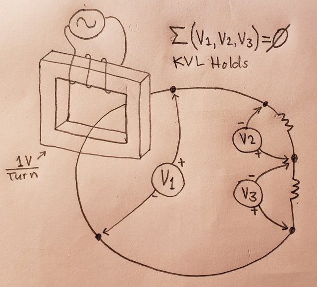
I think we can agree now though that simple 2-terminal closed-magnetic-circuit-core transformer secondary windings work fine as an element in a KVL loop with other components? Or do you still disagree with that?
Are you saying that the electric field produced by a toroidal transformer can induce voltages in other elements in the KVL loop, thus causing KVL to fail?
This tells us that in the blue loops there is no contribution from the magnetic flux in the transformer core and the volt meters in any of them display only what results from the electric currents flowing. That explains why we have 1/3V, 0V, 0V and 2/3V, Ohm's Law lets us expect that. They also sum up to the EMF of 1V which we should expect to find according to Mr. Faraday. These blue loops are those where KVL holds.
Now lets walk through both red loops clockwise. In the R+2R loop the path is with the curl of the electric field, in the 2R loop the path is against the curl, so lets just say we expect an EMF of "-1V" along this path and run with that simplification. We know that the electric field across 2R is 2/3V (measured along a "cold" path) and the EMF is "-1V" and when we sum that up we get to the "-1/3V" that Jesse's magic phase-aware volt meter was showing. Note that I am sticking with Jesse's frame of reference on purpose to explain what he "measures", being fully conscious that it is not a full analogy.
This analysis explains all the measurements without making anyone unhappy except Mr. Kirchhoff, but we can easily accept that, given that the more fundamental laws by Mr. Ohm and Mr. Faraday are satisfied. Jesse's claim that "KVL holds" because all the voltages "sum up to 0" is without basis because of a faulty interpretation of the results obtained.
Objection your honor!
The reason Mr. Kirchhoff is unhappy is because you're categorically ignoring measurements of some of the voltage differences on some of the elements in the loop.
Now the big question is of course, can KVL be somehow made to work in this arrangement, and for that we need to find an equivalent circuit with lumped elements. That will prove to be difficult, because one cannot find a place where to stick a lumped transformer winding or voltage source and still satisfy all the measurements taken in the various places. We can obviously not put it in the wires between the resistors, because we measure 0V across them. It can also not be in "R" and/or in "2R". If we put a 2/3V source "inside" 2R, that would violate the "-1/3V" reading on the rightmost volt meter.
So, where is it? Apparently it is there, but we cannot pinpoint it and measurements between two identical points show different results depending on how we instrument the circuit (1/3V, 2/3V, -1/3V). For circuit theory and KVL this is a nightmare. That's why there are "equivalent circuits" e.g. for transformers which try to model physics with lumped elements full of imaginary numbers and "magic items" like ideal transformers because they relieve engineers of having to think about physics. And to make KVL work. But now and then, when Sir James Clerk Maxwell makes an appearance, everyone is baffled why their circuits don't work.
The only reason we cannot pinpoint it is because it is all the way around. Sure, it MODELS and MEASURES as if it's at the center, but if you look at Faraday, and Maxwell, it's dB/dt inside an area, and measuring it on a solid core of effective infinite length is difficult because the active element of the transformer is no different than our volt meter leads, and they too, suffer from that same effect of induced voltage.
The difficulty in probing is that the volt meter has to be on one side of the infinitely long solenoid. That doesn't mean that there isn't a certain volts per turn of induced EMF, it just means it's difficult to measure in less than 1 turn increments because the volt meter leads have to go around the solenoid an integer number of times, unless we're allowed to run the volt meter probes through the
However, if we use MaxEQ to our benefit, we can find ways to measure the voltage across a transformer turn or a partial turn without our probe leads becoming also voltage sources.
That is how on my Lewin Clock I was able to measure the partial turn voltage differences, because I understand enough to know that above my air core pancake transformer, there are certain planes in which there is no non-conservative field - and by running my probe wires along these planes I was able to measure the exact voltages that KVL predicts.
My Lewin Clock is nothing more than a continuously variable variac. It simply allows the secondary winding taps to be placed at any desired point.
If Ferrofluid wasn't so expensive, I would try the same thing submerged in ferrofluid, basically that would be a liquid core transformer, it would have a closed magnetic circuit and yet a tap could be placed anywhere and the volt meter leads would not be in a non-conservative field, and fractional turn voltages could be easily measured.
And why do I go on about fractional turn? Because here's the shell game we're playing.
First we start off with the given, "KVL IS FOR THE BIRDS." Lewin said it, it must be true.
So people like I come along and say "Ahh, but look, I have a transformer output, I put it in series with some resistors, and I considered these each as elements, measured the voltage differences around the loop, and the sum was zero..
But then the lewinites come back and say "No! You have to create the loop INSIDE a transformer, by forming a KVL ring in a toroid, using HALF turns as elements instead of WHOLE turns."
Why? Because the infinitely long nature of the toroid makes it difficult to probe the voltage induced across a half turn. That's why. It has nothing to do with the fact that KVL works any differently on whole turns or half turns, they all work the same, it's just that it's harder to measure the voltage induced across a partial turn on a toroid using volt meters.
So the entire Lewinite argument is about making the measurement difficult, not that KVL actually fails.
But then people like me come back and come up with ways to measure partial turn voltage differences, and again, KVL holds just fine even with partial turns and correct probing.
And then we end up with this crazyness where you claim there is 0 volts across all the wires, but 1 volt across the resistors, where exactly is the voltage coming from?
Oh? It's induced? So it is there. It's just difficult to measure in certain specific situations which have been designed for it to be difficult to measure.
And that is why Dr. McDonald said that Lewin's loop is within the range of applicability for Kirchhoff's Voltage Equations.
~~~
So at this point can we agree that KVL works fine with a toroidal transformer secondary winding as a two-terminal element in a loop of that plus resistors, like this:
Because all of your "KVL FAILS Proofs" seem to be based on using a two partial turns on an infinite core, can we agree that whole turns on an infinite core work fine with KVL?
Then we can get onto the nitty gritty of why you think partial turns are failing.
Ultimately, a half turn is no different than a full turn, it's just harder to measure the voltage across it on a single magnetic-circuit infinite core.


