Author Topic: Flip-dots  (Read 8530 times)

0 Members and 1 Guest are viewing this topic.

Offline unknowndomainTopic starter

  • Regular Contributor
  • *
  • Posts: 63
  • Country: gb
    • Blog
Flip-dots
« on: June 23, 2012, 11:08:52 pm »
Hey folks,

I have acquired 3x strips of 7 flip dots, they are operated by powering 12V @ 300ma for 1ms to flip them. I am thinking that to drive them I need to operate them in columns and rows as eventually I will have a 21x21 grid. For now I am just trying to figure out what electronics I require to drive these dots, I guess I need some transistors, I was thinking something like a ULN2003a might work?

Can anyone advise?

Tom
 

Offline westfw

  • Super Contributor
  • ***
  • Posts: 4208
  • Country: us
Re: Flip-dots
« Reply #1 on: June 23, 2012, 11:22:28 pm »
Quote
something like a ULN2003a might work
Do you need to reverse polarity to flip the dot back?  A ULN2xxx won't do that.
 

Online Psi

  • Super Contributor
  • ***
  • Posts: 9966
  • Country: nz
Re: Flip-dots
« Reply #2 on: June 23, 2012, 11:24:54 pm »
Could use a dual push/pull optoisolator per dot, some of those can supply 500mA-1A.
Wont be as cheap as other solutions though, but real easy to wire up and drive from a micro.

Eventually, with the 21x21 array, you'd probably want a push/pull fet setup for each row and column

(Assuming they do need reverse polarity to flip back)
« Last Edit: June 23, 2012, 11:29:26 pm by Psi »
Greek letter 'Psi' (not Pounds per Square Inch)
 

Online mikeselectricstuff

  • Super Contributor
  • ***
  • Posts: 13773
  • Country: gb
    • Mike's Electric Stuff
Re: Flip-dots
« Reply #3 on: June 23, 2012, 11:33:00 pm »
Quote
something like a ULN2003a might work
Do you need to reverse polarity to flip the dot back?  A ULN2xxx won't do that.
It could using 2 channels with a couple of pullup resistors. Not very efficient but for a short pulse it probably wouldn't matter much.
Youtube channel:Taking wierd stuff apart. Very apart.
Mike's Electric Stuff: High voltage, vintage electronics etc.
Day Job: Mostly LEDs
 

Offline unknowndomainTopic starter

  • Regular Contributor
  • *
  • Posts: 63
  • Country: gb
    • Blog
Re: Flip-dots
« Reply #4 on: June 25, 2012, 11:14:20 pm »
Hey all, thanks for your help so far,

What is the best way to control one, or several of these units, in a multiplex fashion? I don't really understand what I need to do in order to make a transistor work both ways?

Do you need to reverse polarity to flip the dot back?

Yes it is necessary to reverse the polarity, In simple terms the way these dots work is that the dot has a permanent magnet inside it, and there is also a permanent magnet underneath, by applying a electromagnet around the underneath magnet, you can flip the polls of that magnet causing it to attract or repel the dot above. The dot will stay where it is all the time until you flip the magnet underneath. It requires a 1ms 300ma 12V pulse, or a 0.5ms 300ma 24V pulse.
 

Offline codeboy2k

  • Super Contributor
  • ***
  • Posts: 1836
  • Country: ca
Re: Flip-dots
« Reply #5 on: June 26, 2012, 01:16:47 am »
normally to provide a drive signal where the polarity can be reversed you would use a MOSFET H-bridge.  Most examples you find online will show a motor at the center of the bridge, but you would just replace that with a solenoid.
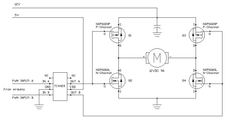


Now, split the bridge apart, left and right, and you have a half-bridge.

Put one side on the rows, and the other side on the columns and drive it appropriately with logic signals.

To flip one way            :  logic LOW on the row, logic HIGH on the column. 
Flip back the other way :  logic HIGH on the row, logic LOW on the column.

There are half-bridge IC's and that can save you on parts count.  I don't know if they make logic level half-bridge drivers. You'd have to search for such a part.

PS: since you are not doing PWM you probably won't need the TC4428 gate driver IC that is in the drawing I found on the web.
« Last Edit: June 26, 2012, 01:27:41 am by codeboy2k »
 

Offline westfw

  • Super Contributor
  • ***
  • Posts: 4208
  • Country: us
Re: Flip-dots
« Reply #6 on: June 26, 2012, 04:32:32 am »
Quote
Yes it is necessary to reverse the polarity
Well, the other possibility would be two coils, one for turning the dot "on", one for "off."  Very similar to "latching relays" in both options and operations.

Since you're eventually looking at an array of dots, you probably need a solution that allows a matrix configuration, rather than having a chip per flip dot.  It's not much different than driving a bipolar LED array, though you need a higher current...
 

Offline unknowndomainTopic starter

  • Regular Contributor
  • *
  • Posts: 63
  • Country: gb
    • Blog
Re: Flip-dots
« Reply #7 on: October 01, 2012, 11:04:02 pm »
Quote
something like a ULN2003a might work
Do you need to reverse polarity to flip the dot back?  A ULN2xxx won't do that.
It could using 2 channels with a couple of pullup resistors. Not very efficient but for a short pulse it probably wouldn't matter much.

Hey Mike,

I am thinking of using either a ULN2003 or ULN2803 but can't really understand how the circuit should be laid out, I tried a few things on the breadboard but didn't succeed, short of using loads of H-Bridge chips, or a High side transistor array, and effectively building H-Bridge's that way.

Anyway, I am not clear on how the pull up would be situated and what sort of value, presumably 4K7 or 10K, if you are able to advise, it would be brilliant!

Thanks

Tom
 

Offline poptones

  • Frequent Contributor
  • **
  • Posts: 709
  • Country: 00
Re: Flip-dots
« Reply #8 on: October 01, 2012, 11:26:21 pm »


This is the perfect application for a 555. Power it from +-9V and use the built in comparator chain to set the on and off levels. Try it and see if the 9V will work.
« Last Edit: October 01, 2012, 11:29:22 pm by poptones »
 

Online mikeselectricstuff

  • Super Contributor
  • ***
  • Posts: 13773
  • Country: gb
    • Mike's Electric Stuff
Re: Flip-dots
« Reply #9 on: October 02, 2012, 12:37:33 am »
Quote
something like a ULN2003a might work
Do you need to reverse polarity to flip the dot back?  A ULN2xxx won't do that.
It could using 2 channels with a couple of pullup resistors. Not very efficient but for a short pulse it probably wouldn't matter much.

Hey Mike,

I am thinking of using either a ULN2003 or ULN2803 but can't really understand how the circuit should be laid out, I tried a few things on the breadboard but didn't succeed, short of using loads of H-Bridge chips, or a High side transistor array, and effectively building H-Bridge's that way.

Anyway, I am not clear on how the pull up would be situated and what sort of value, presumably 4K7 or 10K, if you are able to advise, it would be brilliant!

Thanks

Tom

Two ULN outputs (open collector) , one to each side of the dot.
A resistor from each side to positive. These would be low enough values to pass enough current to flip the dot - probably tens to hundreds of ohms.
Pulse ONE of the  ULN outputs low briefly to flip one way, pulse the other to turn the other way.
This is inefficient as the current draw is over twice what you need to flip the dot, as you are drawing current through both resistors, but is simple and cheap.

Your supply voltage needs to be high enough that the dot will flip with a series resistor value high enough to not draw a stupidly high current through the other resistor - probably at least 2x the flipdot's nominal  rating.
 
Youtube channel:Taking wierd stuff apart. Very apart.
Mike's Electric Stuff: High voltage, vintage electronics etc.
Day Job: Mostly LEDs


Share me

Digg  Facebook  SlashDot  Delicious  Technorati  Twitter  Google  Yahoo
Smf