-
However, you didn't explain how the 2nd base or the 3rd base works. I think it may help some people here,
 .
.
If you could work in the concepts of holes vs. electrons, exchange of charges, emission of electrons, collection of majority carriers, etc., it would impress people more, potentially.
-
However, you didn't explain how the 2nd base or the 3rd base works. I think it may help some people here,
.
If you could work in the concepts of holes vs. electrons, exchange of charges, emission of electrons, collection of majority carriers, etc., it would impress people more, potentially.
Not premium service, some original research required :p
Might not be fully related to the inner workings of common semiconductors
-
Base region or base pin? Just to clarify, in my simple analysis in #121 I'm referring to base as the base 'pin' or component leg as per the thread title. I'm just trying to post up a simplistic model of the common base amplifier for a beginner. I'm posting up how I was initially taught about the BJT when I was a spotty student and the common base is the easiest to understand.
In a simple common base analysis a beginner can crudely model the device as current out = current in (if alpha is very close to 1) or they can use the Shockley equation to try and calculate Ic based on Vbe etc.
But please note that I'm not taking sides. I don't have a horse in this race. In my opinion many of the deeply technical posts in this thread are just going to confuse and alienate a beginner.
-
However, you didn't explain how the 2nd base or the 3rd base works. I think it may help some people here,
.
If you could work in the concepts of holes vs. electrons, exchange of charges, emission of electrons, collection of majority carriers, etc., it would impress people more, potentially.
Not premium service, some original research required :p
Might not be fully related to the inner workings of common semiconductors
It requires a capacitor that can raise it's capacitance overtime but being careful that the capacitor doesn't have enough to feed other bases and moves on to a newer circuit altogether.
-
Well if you insist;
I do not "insist" - but I think that a sequence of questions and answers is the best method to clarify things (and opposite opinions).
Voltage always is fed back in series (and currents in parallel).1.) First statement: The input resistance of an amplifier goes up if a voltage is fed back to the controlling inverting node and it goes down if a current is fed back. (These are basic rules from feedback theory).
This is ambiguous, because both voltage and current can be fed back in series or parallel.
But that`s no answer.
It was a simple yes/no question (Is the rising of the input impedance due to Re feedback an indication for voltage control; yes or no?).I kindly ask you to answer two short questions:
a) Are both points 1) and 2) above, correct or not?
b) Can we derive from the observation in 2) any information about the question if a voltage or a current is fed back to the inverting node?This also makes the question much more complicated than necessary, because you are talking about the impedance of a good capacitor: the FET case. The impedance is already infinite (nearly) at DC, but capacitive at high frequencies, neither of which is very easy to measure. What frequency should it be measured at? How are we to determine whether the feedback has an increasing or decreasing effect on it?
I didn`t mention FET`s case at all. Sorry - but this has nothing to do with the question under discussion.
Tim
Final remark: In my various posts I have listed some effects (on BJT unit level) as well as corresponding circuit examples which can be explained only because the current Ic is determined by the voltage Vbe (rather than the current Ib, which is existent because it cannot be avoided). In addition there are many experts with high reputation (Barrie Gilbert) who are supporting the voltage-control mechanism.
On the other hand - I didn`t hear or read about one single example which would justify or proof the claim of current control.
Are you really not able to reconsider your opinion?
LvW -
Yes - I know. I am not able to understand.Quotelet me try a kind of summary
You don't seem to be able to understand it on a device level, nor a circuit level - both of which we have tried on you.
Perhaps I would inprove my understanding if you could give an answer to my technical questions. So - I would have the chance to learn something. -
In all my 25 years as an RF designer I've never ever heard any of my colleagues argue/bitch over the labelling of how a BJT is 'controlled' in terms of voltage or current.
Thank you for this sentence. This underlines my claim that all of us (if we follow the voltage- or the current-control approach) follow the same steps for designing an amplifier stage. That means: For designing BJT circuit it it not important at all on which "model" we a re relying.
But the funny and surprising situation is as follows (as I have explained in a former reply) : During such a design process all of us treat the current Ib as a kind of "unwanted" (parasitic) current that must be, of course, taken into account. Nevertheless, some people still believe that Ib would determine the value of Ic - and they don`t realize the contradiction.
As I have mentioned - no problem for designing; however, if we start to explain the working principle of some circuits (I have given examples) the contradiction becomes obvious (example: Re feedback, Early effect) .In reality some of them fail to transfer and these are seen as wasted electrons that uselessly flow to the base. But the idea is that they nearly all transfer to the collector load resistor.
Yes - exactly this is the situation (wasted electrons)! Thank you for being the first who is mentioning the common-base configuration.
LvW
-
Thanks for posting that.Quotelet me try a kind of summary
You don't seem to be able to understand it on a device level, nor a circuit level - both of which we have tried on you.
Here is another attempt - which I indicated quite a while for you.
The following is a simulation of two ideal devices, G1 on the left is a voltage controlled current devices and F1 on the right is a current controlled current devices. Both are configured into a gain stage.
The graph shows a dc sweep where Vin goes from 0v to 100mv, and Vout1 / Vout2 goes from 5v to 4v, as expected - Vout2 was shifted upwards by 0.1 so it is not right on top of Vout1.
Now, F1 and G1 are completely different devices in that one is voltage-controlled and the other is current controlled.
Question for you, which of them is a bjt and which is a mosfet?
:0
Indeed the response is the same, irrespective of whether it's current or voltage controlled.
Now look at the input impedance of the current controlled amplifier and you find it's pretty similar to what you'd expect from a BJT amplifier.
What simulation package do you use?
I tried LTSpice but it doesn't have a current controlled current source, so I used the voltage controlled current source and connected a 1R resistor across the input terminals and it works quite well. -
Thanks for posting that.Quotelet me try a kind of summary
You don't seem to be able to understand it on a device level, nor a circuit level - both of which we have tried on you.
Here is another attempt - which I indicated quite a while for you.
The following is a simulation of two ideal devices, G1 on the left is a voltage controlled current devices and F1 on the right is a current controlled current devices. Both are configured into a gain stage.
The graph shows a dc sweep where Vin goes from 0v to 100mv, and Vout1 / Vout2 goes from 5v to 4v, as expected - Vout2 was shifted upwards by 0.1 so it is not right on top of Vout1.
Now, F1 and G1 are completely different devices in that one is voltage-controlled and the other is current controlled.
Question for you, which of them is a bjt and which is a mosfet?
:0
Indeed the response is the same, irrespective of whether it's current or voltage controlled.
Now look at the input impedance of the current controlled amplifier and you find it's pretty similar to what you'd expect from a BJT amplifier.
Hi Hero999 - up to now, I didn`t comment this example from dannyf because it does not meet the point (for my opinion).
However, because of your answer - I have changed my mind.
This example does not meet the point (that means: The subject of our discussion) because it describes CIRCUITS with external elements.
But this was not the problem to be discussed in this thread. Instead, we were discussing the control mechanism INSIDE the BJT.
Let me take another simple example: It is commonly accepted to treat the classical opamp as an voltage amplifier (does this apply also for the "current-control group" in case of BJT input stage?). However, with external elements the whole CIRCUIT can be used, for example, as a current amplifier or as a current-to-voltage converter. Buth this operation does not say anything about the transfer characteristics of the opamp unit alone. Do you know what I mean?
More than that, several times I have emphasized the fact that during DESIGN of an amplifier circuit it does not matter at all how/why the collector current of a BJT changes its value.
There is no doubt, that I can send a current into the base and watch if and how the current Ic varies. But this cannot tell us anything about the control mechanism because the same is possible with a voltage.
But the situation changes as soon as we have to explain to somebody else WHY the BJT (or a circuit with a BJT) shows a certain behaviour.
I have presented many examples, which cannot be explained with current-control - on the other hand, nobody was in the position to proofe the opposite.
(I don`t know if I have mentioned already that, for example, the EARLY effect can only be explained using voltage control. It`s that simple.
Perhaps it is even better and more clear to say: The existence of the Early effect, in fact, prooves that the BJT is a voltage controlled part.) -
But the situation changes as soon as we have to explain to somebody else WHY the BJT (or a circuit with a BJT) shows a certain behaviour.
Here I think lies the root of all the problems. You see, in physics and in science generally there is no answer to the question of why something happens. Science can only answer the question of what happens, and what will happen.
We do experiments and gather data, and then we try to fit a mathematical model to the data. If we have a good model it will predict the results of other experiments we haven't done yet. If we have a bad model it will not, and we discard that model. The best models, the most convenient models to use, have fewer parameters that are easier to determine. We try to settle on the best models if we can, because they suggest we have somehow got "closer" to what is really going on.
So trying to ask what "controls" something else, if we mean anything other than what is the simplest model, is futile.
Try a question from another field, aerodynamics. Why do planes fly? One person will say that the air flowing over the wing flows faster over the top causing lower pressure above the wing than below it. This pressure differential multiplied by the wing area produces a lift force that holds the plane up.
Another person will argue that this is totally wrong and cannot possibly explain why a wing produces lift. The real explanation is that the wing when moving through the air deflects air downwards, like the draft you feel when standing underneath a helicopter. By Newton's law of motion, that every action produces an equal and opposite reaction, the air deflected downwards lifts the plane upwards. This is why planes fly.
So it seems we need to argue about this instead. Is the lift on a wing produced by pressure or by air flow? -
So it seems we need to argue about this instead. Is the lift on a wing produced by pressure or by air flow?
Pressure. If it were angle of the wing, a wing with the bottom surface parallel to the ground (or perpendicular to the force of gravity) would not generate lift.
Also, I am not sure if you intended this, but the air-flow / pressure are one and the same explanation. -
And see, this is the reason such discussions often founder. Can you point to one place in my post where I mentioned angle of the wing? I said "A" or "B" are alternative explanations. And you chime in with 'oh, but it can't be "C" because...' Well, fine, it can't be "C", but who suggested it was?So it seems we need to argue about this instead. Is the lift on a wing produced by pressure or by air flow?
Pressure. If it were angle of the wing, a wing with the bottom surface parallel to the ground (or perpendicular to the force of gravity) would not generate lift.QuoteAlso, I am not sure if you intended this, but the air-flow / pressure are one and the same explanation.
Quite right. If air flow wasn't directed downwards there would be no lift force exerted on the wing. I'm glad we agree about that. -
Quote
I'm glad we agree about that.
You are so not understanding what the other poster was saying. Lift doesn't have to be generate by pushing down air. And rotorcraft doesn't work the way you think it does.
Read an Aerodynamic 101 textbook. -
i've been chatting with a few ex collegues on this.
It is really very simple
A bipolar transistor as amplifier has two defining parameters :
the common emitter current gain is called Beta ( or hFE)
the common base current gain is called Alpha
both are .... ratios. <- fill in the blank .... -
i've been chatting with a few ex collegues on this.
It is really very simple
A bipolar transistor as amplifier has two defining parameters :
the common emitter current gain is called Beta ( or hFE)
the common base current gain is called Alpha
both are .... ratios. <- fill in the blank ....
You talk as if these are the only defining properties of the transistor and everything else necessarily falls out of them. I could say the same thing about the parameters of the Ebers-Moll equation, and I'd have a more accurate model as well (as yours doesn't account for anything translinear).
Also, these are only one parameter, each is directly a function of the other.
-
Of course - we all know what's really controlling the things:
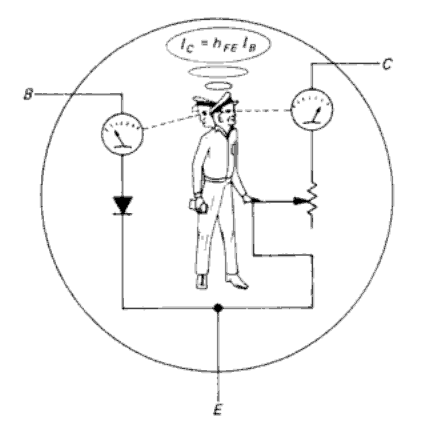
This dude, and a bit of magic smoke to keep him happy
-
Of course - we all know what's really controlling the things:
This dude, and a bit of magic smoke to keep him happy
Where does his poop and pee go?!?!
Sent from my Tablet -
Oh, I am intimately familiar with the base, she always claim she needs noting, but we all know that current is what she craves, just a little bit she says, but we all know it ends up being much more than that, often way beyond our budget, but what can we do, she needs the current now to perform what we expect of her.
With enough current she might just open her holes for you.
Sent from my Tablet -
Of course - we all know what's really controlling the things:
This dude, and a bit of magic smoke to keep him happy
Where does his poop and pee go?!?!
Common sense will indicate it will go to the collector, but it goes into the emitter.
-
Of course - we all know what's really controlling the things:
This dude, and a bit of magic smoke to keep him happy
Where does his poop and pee go?!?!
Common sense will indicate it will go to the collector, but it goes into the emitter.
That depends on whether it's NPN or PNP... -
Of course - we all know what's really controlling the things:
This dude, and a bit of magic smoke to keep him happy
Where does his poop and pee go?!?!
Common sense will indicate it will go to the collector, but it goes into the emitter.
That depends on whether it's NPN or PNP...
definitely a Poop 'N Pee so collector it is (I think)
-
Of course - we all know what's really controlling the things:
This dude, and a bit of magic smoke to keep him happy
Where does his poop and pee go?!?!
Common sense will indicate it will go to the collector, but it goes into the emitter.
That depends on whether it's NPN or PNP...
definitely a Poop 'N Pee so collector it is (I think)
Brilliant!
Now we're finally discussing what this thread truly is: Shit.
Sent from my Smartphone -
Doesnt matter. A bipolar transistor is a current driven current amplifier.i've been chatting with a few ex collegues on this.
It is really very simple
A bipolar transistor as amplifier has two defining parameters :
the common emitter current gain is called Beta ( or hFE)
the common base current gain is called Alpha
both are .... ratios. <- fill in the blank ....
You talk as if these are the only defining properties of the transistor and everything else necessarily falls out of them. I could say the same thing about the parameters of the Ebers-Moll equation, and I'd have a more accurate model as well (as yours doesn't account for anything translinear).
Also, these are only one parameter, each is directly a function of the other.
The gain is defined as ratio of two currents.
And i'm done with this topic. Do whatever you please. I don't care anymore. It can be approached from both perspectives. Fact remains : no base current is no collector current. -
But the situation changes as soon as we have to explain to somebody else WHY the BJT (or a circuit with a BJT) shows a certain behaviour.
Here I think lies the root of all the problems. You see, in physics and in science generally there is no answer to the question of why something happens. Science can only answer the question of what whappens, and what will happen.
We do experiments and gather data, and then we try to fit a mathematical model to the data. If we have a good model it will predict the results of other experiments we haven't done yet. If we have a bad model it will not, and we discard that model. The best models, the most convenient models to use, have fewer parameters that are easier to determine. We try to settle on the best models if we can, becaues they suggest we have somehow got "closer" to what is really going on.
So trying to ask what "controls" something else, if we mean anything other than what is the simplest model, is futile.
Really "futile"?
IanB - here I am not with you. I know what you probably mean; and I agree with you - as far as "natural laws" are concerend.
However, based on these fundamental laws and rules, we have a lot of phenomena which can and must be explained - starting with our definitions for "voltage" and "current". Both terms are used for finding other rules and formulas which, of course, can be explained (voltage divider, superposition,...).
And the same applies - for my opinion - to the BJTs control mechanism.
More than that, I think it is really necessary to explain this mechanism - at least when students have problems to solve some obvious contradictions.
Imagine the following situation: Introducing the BJT I have stated that Ic is determined by Ib using the simple relation Ic=B*Ib.
Now - after some additional lessons - I explain the temperature dependence of the curent Ic and tell them that - in order to keep Ic constant - I must reduce the voltage Vbe by -2mV per degree temp. change.
Of course, some students will ask: Huhhh? We thougt it is the current Ib that controls Ic. Suddenly it is the voltage Vbe? (That`s what I have experienced often.)
And why this value of -2mV/K ?
And I must answer and explain that this value is not only measured but that this value was calculated based on charged carrier physics in the pn region of the transistor.
Do you understand the dilemma? It is really not sufficient to say "doesn`t matter , current or voltage" .
I have to make a decision - and (as I have demonstrated with various examples): A current-control mechanmism cannot explain how BJT circuits really work. -
Imagine the following situation: Introducing the BJT I have stated that Ic is determined by Ib using the simple relation Ic=B*Ib.
Now - after some additional lessons - I explain the temperature dependence of the curent Ic and tell them that - in order to keep Ic constant - I must reduce the voltage Vbe by -2mV per degree temp. change.
Of course, some students will ask: Huhhh? We thougt it is the current Ib that controls Ic. Suddenly it is the voltage Vbe? (That`s what I have experienced often.)
And why this value of -2mV/K ?
This is really a matter of teaching and order of presentation. You have first presented a simple model of the operation of a transistor, of the form f(Ib, Ic, B) = 0, where B is a parameter and Ib, Ic are model variables. Given a value of B, then for any value of Ib you can fix Ic, or for any value of Ic you can fix Ib. But it is important to explain that this is a simplified model that abstracts away many details, and is only valid in a narrow region of operation.
Later, it will become necessary to introduce more elaborate models of operation, models that include variables Vbe, Vce, Ib, Ic and perhaps the operating temperature, T. With such a model in place, it becomes possible to talk about the influence of T on the other variables. One can also talk about when it is appropriate to use the simple model and when the more detailed model is needed.
But even with the more detailed model, it is not really possible to say that one variable is a cause and another variable is an effect. This is choice is a matter of perspective and intent. The model variables are in relationship to each other. If you fix some variables of your choice, then according to the degrees of freedom of the model other variables will be determined. For instance you could choose a desired value of Ic and determine appropriate values of other variables to achieve this.