Author Topic: WTF Xilinx  (Read 23495 times)

0 Members and 1 Guest are viewing this topic.

Online Bud

  • Super Contributor
  • ***
  • Posts: 7126
  • Country: ca
Re: WTF Xilinx
« Reply #75 on: June 12, 2020, 04:55:01 pm »
Even if we make crappy GUI, there are common principles that if applied, make it easier to use. For instance, logical flow of menus items from left to right, i.e. File menu on the lefthand side of the menu bar is where you start working on a net new document. Help menu on the righthand side since it is an auxiliary item and not often used. But some people make GUIs so unintuitive you have no idea where to begin, as they place the entry menu somewhere in the middle of the menu bar, or worse yet no menu bar but a bunch of buttons, like two dozens of them in a random order.
Facebook-free life and Rigol-free shack.
 

Online SiliconWizard

  • Super Contributor
  • ***
  • Posts: 15423
  • Country: fr
Re: WTF Xilinx
« Reply #76 on: June 12, 2020, 04:55:20 pm »
I knowingly take shortcuts in the GUI design that result in less coding work to implement rather than doing it the best way. Programmers making GUIs often do that without even realizing. So its all too easy to make a crappy GUI that actually wastes time rather than saves it.

You're making a good point, which is another reason why UI design is best done by non-developers. Not only is that a skill in itself (that many developers don't have), but as you said, most developers will, even if just not consciously, make UI decisions based on how easy or hard it is to implement.

In other words, and to IMHO summarize the current "problem" with software development which is on-topic here, development teams (/management) tend to favor makiing their own life easier (lower dev costs/etc.) rather than trying to make their customers' life easier. They put their own needs above those of their users.

The result is what we have now, with very few exceptions.
 

Online NorthGuy

  • Super Contributor
  • ***
  • Posts: 3248
  • Country: ca
Re: WTF Xilinx
« Reply #77 on: June 12, 2020, 05:51:30 pm »
When i want to place down a text i hit P then S then Tab to open the editor, type in the text, hit Enter to close it, then click where i want to put it.

People are different. I find it easier to type

Code: [Select]
moveto Target
move 100 100
chars 8 "My Text"

then press the Compile button and observe the results. What's more important to me - I have not only placed the text, I also tied it to the point named "Target", which means that if the Target moves, the text moves too.

or I can type

Code: [Select]
def text_offset_x 100
def text_offset_y 100
def text_size 8

...

moveto Target
move text_offset_x text_offset_y
chars text_size "My Text"

After this, I copy and paste the bottom part 50 times and change the point names and texts - I have placed 50 labels which are all located at exact same relation to their respective targets, and will move with the targets wherever they go. Now I see that the text it to small, so I scroll up and change

Code: [Select]
def text_size 8
to

Code: [Select]
def text_size 10
press the Compile button and observe the results. Or I can tweak offsets in a similar way. In my mind, this saves me lots of time.

I don't know how you change the position of 50 labels relative to their respective targets simultaneously with Altium. I tried such things. You spend time to make sure you click on the text, not on a myriad other things around, then you start dragging. You want to move 5 points directly to the left, but the stubborn mouse wants to move up and down as well, and it takes really long time to achieve good placement. Then you repeat this 50 times. I am really bad at this. Changing the text and compiling is much easier for me. Of course, graphical editing may work better for you. People are different.
 

Offline 0db

  • Frequent Contributor
  • **
  • Posts: 336
  • Country: zm
Re: WTF Xilinx
« Reply #78 on: June 12, 2020, 05:57:20 pm »
Long time ago I created a small program to generate PCB traces for the one-sided PCBs which I was doing by myself - for prototyping, as well as different gadgets for my own use. I invented a simple language (although language is too big of a word for it) for this. Then, during the years, as I wanted to do more with it, I was adding new features. So, I added objects, multi-layer, mirroring, auto-bending, gifs, gerbers, bom, length matching etc. I wasn't planning these features, I just added them when I felt an effort of adding a feature would save me a supposedly bigger effort of getting by without it. As a result, I still use it to make gerbers for the PCBs I order. And it works perfectly for me. I can create new PCBs very quickly, and exactly the way I want. So, having software which is designed specifically for you is rather a good thing.

EagleCad has ULP scripting. Which is ok for this.
 

Offline Berni

  • Super Contributor
  • ***
  • Posts: 5031
  • Country: si
Re: WTF Xilinx
« Reply #79 on: June 12, 2020, 06:17:20 pm »
Then again you also need the right kind of professional UI/UX designers working on it.

For example the UI for Windows fell off a cliff after Win 7 and it still has not fully recovered with Win 10. It was like they are trying to outdo Apple in making things look simplistic, but missed the mark by a mile. Half the menus and UI elements still feel like badly made half finished phone apps.

In this regard i applaud Xilinx for giving there IDE a refresh, it lets them bring it up to spec for what a modern application looks like. The tools from Altera/Intel are still stuck in the 90s and include all the 90s UI quirks. Same for LT Spice.


press the Compile button and observe the results. Or I can tweak offsets in a similar way. In my mind, this saves me lots of time.

I don't know how you change the position of 50 labels relative to their respective targets simultaneously with Altium. I tried such things. You spend time to make sure you click on the text, not on a myriad other things around, then you start dragging. You want to move 5 points directly to the left, but the stubborn mouse wants to move up and down as well, and it takes really long time to achieve good placement. Then you repeat this 50 times. I am really bad at this. Changing the text and compiling is much easier for me. Of course, graphical editing may work better for you. People are different.

Yes this is where the good UI is separated from bad UI

If i need to do mass changes then there is the "Find similar" tool that pops up a window with all the properties of the currently selected object so that i ca quickly generate a search query in a few clicks that selects all the relevant objects or masks them for editing. So i can for example find all text objects on the top overlay layer that use a 2mm high Arial font, then drag a selection box around the ones i want to mess with, then change the size to 3mm for all of them using the inspector window. If i need to generate a bunch of objects programmatically then i create one manually, open the List window, copy the spreadsheet into excel as a starting point, generate a table of objects i want then paste the table back in to have the objects appear.

PCB tools with a crap UI might have you going around and changing the text one by one. Not that Altium has a perfect UI tho, there are plenty of stupid quirks but overall it tends to be better than a lot of other tools.

But i am pretty curious how those PCBs look like since its not easy programming a PCB package from scratch.
 

Online NorthGuy

  • Super Contributor
  • ***
  • Posts: 3248
  • Country: ca
Re: WTF Xilinx
« Reply #80 on: June 12, 2020, 06:39:52 pm »
If i need to do mass changes then there is the "Find similar" tool that pops up a window with all the properties of the currently selected object so that i ca quickly generate a search query in a few clicks that selects all the relevant objects or masks them for editing. So i can for example find all text objects on the top overlay layer that use a 2mm high Arial font, then drag a selection box around the ones i want to mess with, then change the size to 3mm for all of them using the inspector window.

Do you find it difficult to change a single number in the source text file compared to all these manipulations?

And, if I understand you correctly, if you have any other unrelated labels with 2mm Arial which are not the ones you can change, the tool will find them too, and you would have to manually separate labels into "do" and "don't" categories every time you need to make a mass change. Certainly not as bad as changing one by one, but still a lot of work, isn't it?
 

Offline asmi

  • Super Contributor
  • ***
  • Posts: 2828
  • Country: ca
Re: WTF Xilinx
« Reply #81 on: June 12, 2020, 07:09:09 pm »
People are different. I find it easier to type

then press the Compile button and observe the results. What's more important to me - I have not only placed the text, I also tied it to the point named "Target", which means that if the Target moves, the text moves too.
If you haven't yet, you should give a try to Cadence Orcad/Allegro PCB - everything can be scripted there and/or typed in a command in a command line, I use it a lot when creating footprints.

Online NorthGuy

  • Super Contributor
  • ***
  • Posts: 3248
  • Country: ca
Re: WTF Xilinx
« Reply #82 on: June 12, 2020, 07:30:07 pm »
But i am pretty curious how those PCBs look like since its not easy programming a PCB package from scratch.

This is not a package - a small program - 6k lines of source, 125KB executable.

PCBs look well, although it depends on the manufacturer, not on how you generate gerbers. Here's a screenshot of my program along with the corresponding fragment of the real PCB. This is a 6-layer PCB generated from 12k lines of source, although, as you can see on the screenshot, these lines of code are very short.

Screenshot:


PCB:


Offline Berni

  • Super Contributor
  • ***
  • Posts: 5031
  • Country: si
Re: WTF Xilinx
« Reply #83 on: June 12, 2020, 08:11:03 pm »
Do you find it difficult to change a single number in the source text file compared to all these manipulations?

And, if I understand you correctly, if you have any other unrelated labels with 2mm Arial which are not the ones you can change, the tool will find them too, and you would have to manually separate labels into "do" and "don't" categories every time you need to make a mass change. Certainly not as bad as changing one by one, but still a lot of work, isn't it?

It all depends on the circumstances. Is my cursor already on the number i need or do i first need to find the number in a 800 line long file? Did i have the foresight when doing it to put all the things i needed to change under a single definition? Or do i have to hunt down 3 other definitions to change all the stuff i wanted to change. Or do things i don't want to change also use this same defined number, in that case i need to define a new number and manually go back and update the ones i don't want to change to the new definition.

I personally find i need GUI help even when navigating trough source code. Its alright to start with, but once i have to find my way around a few 1000s of lines of code then i start getting annoyed working with it in a plain text editor. I can no longer remember what each function looks like or where it is. Sure i group things together logically, but that doesn't help when one module of code spans many 100s of lines and i need to find that one thing im looking for in there. So instead i tend to use smart code editors that understand the programing language i use, this gets me autocomplete of function names or variable names (saving me time in not having to remember the exact name, reducing errors due to remembering the wrong name and in some cases saving a good bit of typing), it gives me live preview of a function while i am filling out its arguments, it lets me jump to the definition of a function with just one keypress, a few more let me find all the places where this function is used, a few more let me rename the function while also renaming all references to it in all the rest of the code automatically. I can collapse down parts of code im not working on like a tree. It helps me in finding what brackets go with what by highlighting them. It highlights syntax errors as i type in order to save a few compile iterations due to silly typos...etc

At first i didn't think i need such fancy pants smart code editors, but then i tried a few and afterwards tried to do things without them again, that's when it hit me how clumsy and slow i was with a plain text editor. A normal text editor suddenly felt like soldering with boxing gloves on. Yet i was perfectly happy with one before.

Oh and on the topic of automation. Altium does have scripting support but mostly in the form of Delphi, tho i hear you can use VB or JS too. Did have some fine tweaks for documentation generation done in it but its pretty annoying. As for making footprints, there is a footprint generator wizard that just needs to be told what type of package it is (SMD Resistor, SOIC, TQFP, QFN, BGA...etc) and given a few key measurements from the datasheet, few clicks later it spits out a finished ready to use footprint including a 3D model of the chip placed on top of it. It will do a similar thing for schematic symbols if the datasheet contains a pinout in any copy pastable form. I find these wizards quicker than coding it.
 

Offline Berni

  • Super Contributor
  • ***
  • Posts: 5031
  • Country: si
Re: WTF Xilinx
« Reply #84 on: June 12, 2020, 08:22:57 pm »
But i am pretty curious how those PCBs look like since its not easy programming a PCB package from scratch.

This is not a package - a small program - 6k lines of source, 125KB executable.

PCBs look well, although it depends on the manufacturer, not on how you generate gerbers. Here's a screenshot of my program along with the corresponding fragment of the real PCB. This is a 6-layer PCB generated from 12k lines of source, although, as you can see on the screenshot, these lines of code are very short.

That does actually look rather neat.

Tho i do wonder how it is wrangling traces around in tight spots with just numbers. As well as how do you keep track of what connects to what on a board of this complexity (I quickly got used to the computer taking care of that for me).
 

Online NorthGuy

  • Super Contributor
  • ***
  • Posts: 3248
  • Country: ca
Re: WTF Xilinx
« Reply #85 on: June 12, 2020, 09:12:58 pm »
It all depends on the circumstances. Is my cursor already on the number i need or do i first need to find the number in a 800 line long file? Did i have the foresight when doing it to put all the things i needed to change under a single definition? Or do i have to hunt down 3 other definitions to change all the stuff i wanted to change. Or do things i don't want to change also use this same defined number, in that case i need to define a new number and manually go back and update the ones i don't want to change to the new definition.

This is the same as in C. You figure out what to define, and, of course you may make mistakes.

Its alright to start with, but once i have to find my way around a few 1000s of lines of code then i start getting annoyed working with it in a plain text editor.

In this particular case it's very easy. You just click the object and it'll take you to the line where it is defined.

Tho i do wonder how it is wrangling traces around in tight spots with just numbers. As well as how do you keep track of what connects to what on a board of this complexity (I quickly got used to the computer taking care of that for me).

There's no assurance, but the traces go from pin to pin, so it's easy to check. For example

Code: [Select]
layers T
tracewidth TrF
moveto A.T3
trace -20 20
Via
layers S1
trace -120 0
trace -230 -230
trace 0 -60
trace -680 -680
trace 0 -1190
Via
layers T
bendto OHB.In1

You can see how it jumps to the signal layer, then makes few bends, then comes out back to the top and connects to the destination. "bendto" means it goes at 45 degree angle then turns vertical or horizontal and arrives to the object. "angleto" would make it go vertical or horizontal then arrive to the object at 45 degree angle. "Via" is an object which is defined at the beginning of the file as:

Code: [Select]
class Via
  layers T S1 S2 V G G2
  round ViaSize
  hole ViaDrill
end


If the next trace is similar you can simply copy and paste. Then you would need to correct few numbers, but not that much. Say the trace next to the one described above is:

Code: [Select]
layers T
tracewidth TrF
moveto A.T4
trace -20 20
Via
layers S1
trace -20 -20
trace -132 0
trace -218 -218
trace 0 -60
trace -680 -680
trace 0 -1208
Via
layers T
bendto OHB.In2

Of course, a very long and windy trace may take couple minutes to sort out.
 

Online Nominal Animal

  • Super Contributor
  • ***
  • Posts: 6952
  • Country: fi
    • My home page and email address
Re: WTF Xilinx
« Reply #86 on: June 13, 2020, 09:38:44 am »
NorthGuy, there is nothing odd in that approach.  Others may find it useful too.

It is the same approach to PCBs as OpenSCAD has to 3D objects, or POV-Ray has to describing scenes to be rendered/raytraced.  OpenSCAD is extremely common for 3D printed objects, because you can easily make them parametric.  POV-Ray is useful when exploring procedural graphics, like realistic trees or grass or such, that have way too much individual detail (sub-objects or bifurcation) to do "by hand".

Just like Graphviz is a superior tool to auto-generating graphs (it too uses a simple language to describe the relationships; its various sub-tools will generate different types of graphs from those relationships), and makes it easy for others to generate graphs from e.g. internal structure of their programs or their data structures, or even e.g. website navigation charts (I've done all three), making it a valuable development tool; given a suitable interface, some enterprising developers might experiment with different algorithms for auto-routing for yours. (It is not that easy to experiment with this stuff in existing EDA packages like KiCAD, because examining exactly how the generated net is "bad" is a critical part of the development, and you need the coordinates in human-readable form for that – AIUI autorouter developers use their own "test-benches" for this, and that adds to the initial hurdle of developing new autorouting schemes.)
 
The following users thanked this post: NorthGuy

Offline Berni

  • Super Contributor
  • ***
  • Posts: 5031
  • Country: si
Re: WTF Xilinx
« Reply #87 on: June 13, 2020, 01:10:43 pm »
Ah so it does have a bit of interactivity to it.

It does look like a nice compact language. I can see this making a lot of sense for digital circuitry that typically goes directly from pin to pin. But for analog stuff that tends to branch a lot, there i don't think i would be able to follow along the text without having the schematic on paper in front of me. Especially since i tend to mangle analog circuitry PCB layouts in to a shape very different than the schematic in an attempt to squeeze it together into a smaller area of the board or avoid vias.

Certainly a good approach in making a simple compact PCB tool.

But still i don't think such text based editing would be faster than a well made GUI all together. Where text might have an advantage is being more flexible, like if you suddenly want hexagonal shaped via pads for some reason, while some GUI PCB packages might not support that, so making it happen would be a clumsy manual hack there.
 

Offline 0db

  • Frequent Contributor
  • **
  • Posts: 336
  • Country: zm
Re: WTF Xilinx
« Reply #88 on: June 13, 2020, 02:24:31 pm »
OpenSCAD

bah, I have seen it a lot of times, and every time I talked with a mechanical engineer, he/she told ... pfft OpenSCAD. They seem to prefer tools with a GUI.
« Last Edit: June 13, 2020, 04:59:06 pm by 0db »
 

Online Nominal Animal

  • Super Contributor
  • ***
  • Posts: 6952
  • Country: fi
    • My home page and email address
Re: WTF Xilinx
« Reply #89 on: June 13, 2020, 02:49:09 pm »
OpenSCAD
bah, I have seen it a lot of time, and every time I talked with a mechanical engineer, he/she told ... pfft OpenSCAD. They seem to prefer tools with a GUI.
That's mostly because they either have the components in their CAD programs, or because they can do prototyping on real metal using CNCs.  It's a different niche.  OpenSCAD is for those who know what properties the object needs, but not necessarily exactly what shape that is.  Rather interesting, eh?
 

Online NorthGuy

  • Super Contributor
  • ***
  • Posts: 3248
  • Country: ca
Re: WTF Xilinx
« Reply #90 on: June 13, 2020, 03:33:31 pm »
It is the same approach to PCBs as OpenSCAD has to 3D objects

Great. Thank you. I like it. and 0db's reaction prove the point I had all along. There are many approaches, which have different flows and different GUIs. Different people prefer different interfaces and different flows.
 

Online NorthGuy

  • Super Contributor
  • ***
  • Posts: 3248
  • Country: ca
Re: WTF Xilinx
« Reply #91 on: June 13, 2020, 03:40:06 pm »
I can see this making a lot of sense for digital circuitry that typically goes directly from pin to pin. But for analog stuff that tends to branch a lot, there i don't think i would be able to follow along the text without having the schematic on paper in front of me.

You're absolutely right. I only do digital. Even interfaces to ADCs are still digital point-to-point traces. Branching is rare and often trivial, such as in power distribution or pull-ups. I don't know how would it fare if I had to build a big amplifier with lots of transistors.
 

Offline 0db

  • Frequent Contributor
  • **
  • Posts: 336
  • Country: zm
Re: WTF Xilinx
« Reply #92 on: June 13, 2020, 06:56:46 pm »
It's a different niche.  OpenSCAD is for those who know what properties the object needs, but not necessarily exactly what shape that is.  Rather interesting, eh?

I would also consider Pro/E, Blender, Maya and Wildfire.

In particular Blender and WF have some scripting capabilties.
Somethink like the ULP scripting we can find in EagleCad.

Not to bad as "GUI-oriented but with scripting capabilities"  :D
 

Online NorthGuy

  • Super Contributor
  • ***
  • Posts: 3248
  • Country: ca
Re: WTF Xilinx
« Reply #93 on: June 13, 2020, 07:15:45 pm »
Not to bad as "GUI-oriented but with scripting capabilities"  :D

These are different approaches which cannot be combined. Either you write the source and the tool uses it, but does not touch it. Or the tool maintains the source in its own format and you use the tool to modify the source.
 

Offline 0db

  • Frequent Contributor
  • **
  • Posts: 336
  • Country: zm
Re: WTF Xilinx
« Reply #94 on: June 13, 2020, 08:19:23 pm »
These are different approaches which cannot be combined.

In EagleCAD, you can make circuits without the GUI, just typing commands on the console, you can make circuits with the GUI, and you can also write ULP scripts to parametrize certain actions, like BOM? Labels adjustuments? or even making parametric components, like copper pcb resistors? copper pcb spirals? copper pcb flat motor inductors?, you write the script, job done; and not only you can use the script in graphic mode, but you can also define a button in your 3D mouse to call the right script on demand!
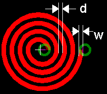
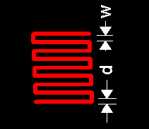


Yesterday I wrote a script to created the stuff I am talking about. And in 1 second it made a copper pcb resistor, a wire of 20000 meters mm of length twisted several times to stay in 20x60mm of area. Its attributes are all parameters filled in a GUI that I wrote inside the script itself.

If you do it by hands, designing that long copper pcb resistor will take more time, and if you do a mistake with some of the parameters, or if you change your mind about its properties (too low resistance? too high resistance? too big area?),  you have to delete an go back to the beginning of the whole process.

ULP also allows you to operate with the routing algorithm, and this means you can implement your own routing strategy for certain weird components.

Maya, Blender,  (Pro/E) Wildifire do the same but for the mechanical stuff.

I don't know what KiCad offers.

edit:
typo
« Last Edit: June 13, 2020, 11:25:36 pm by 0db »
 

Online NorthGuy

  • Super Contributor
  • ***
  • Posts: 3248
  • Country: ca
Re: WTF Xilinx
« Reply #95 on: June 13, 2020, 10:55:53 pm »
Yesterday I wrote a script to created the stuff I am talking about. And in 1 second it made a copper pcb resistor, a wire of 20000 meters of length twisted several times to stay in 20x60mm of area.

Even with 0.05 mm trace width/spacing, you can only fit 20x60/(0.05*2) = 12000 mm = 12 meters of wire into that space. 20 km would require 1667-layer PCB, not counting the space for vias.

I guess you could've created a script which produced the whole PCB, which would then be compiled into Eagle's brd file and then to gerber by the second pass. But how would you combine this with GUI? Whatever changes you made to PCB with GUI wouldn't change your script. And vise-versa - as soon as you pass the result of your script and edit it with GUI, any changes you make to the script won't affect it any more.
 

Offline 0db

  • Frequent Contributor
  • **
  • Posts: 336
  • Country: zm
Re: WTF Xilinx
« Reply #96 on: June 13, 2020, 11:17:31 pm »
But how would you combine this with GUI? Whatever changes you made to PCB with GUI wouldn't change your script

You use a text notepad to change the text of the script, and you use the GUI to apply the script to the pcb, to the schematic, or to the library. The GUI simplifies how you apply the script. E.g. you can select group, use the 3D mouse to zoom, rotate, and select/deselect all the items to be passed to the script.
 

Offline 0db

  • Frequent Contributor
  • **
  • Posts: 336
  • Country: zm
Re: WTF Xilinx
« Reply #97 on: June 13, 2020, 11:21:14 pm »
20000 meters


it's 20000 mm not meters. Typo.
 

Online NorthGuy

  • Super Contributor
  • ***
  • Posts: 3248
  • Country: ca
Re: WTF Xilinx
« Reply #98 on: June 13, 2020, 11:41:32 pm »
You use a text notepad to change the text of the script, and you use the GUI to apply the script to the pcb, to the schematic, or to the library. The GUI simplifies how you apply the script. E.g. you can select group, use the 3D mouse to zoom, rotate, and select/deselect all the items to be passed to the script.

Your script simply extends the capabilities of the GUI. It doesn't change the principle.
 

Offline 0db

  • Frequent Contributor
  • **
  • Posts: 336
  • Country: zm
Re: WTF Xilinx
« Reply #99 on: June 14, 2020, 12:00:45 pm »
Your script simply extends the capabilities of the GUI. It doesn't change the principle.

It's not "my script", it's how EagleCad, Wildifire, Maya, and a lot of tools do thier job.

And I have never written it has to change the principle.

It's always the same principle, although things have improved a lot.

Pro/ENGINEER 1 - 1987
Pro/ENGINEER 14.0 - 1994

Before 1995, Pro/E only had limited GUI features, therefore you had to know things manually on the console. It meant you have to master solid conceps about linear algebra, geometry, and tensor calculation. This in order to extend the capabilities of the limited GUI.


Share me

Digg  Facebook  SlashDot  Delicious  Technorati  Twitter  Google  Yahoo
Smf