-
So after installing latest firmware this POS (1202X-E) still locks up!!!

-
So after installing latest firmware this POS (1202X-E) still locks up!!!
Then we need to know more.
Did you perform the Self Cal after FW installation?
Under what usage and settings does it lock ?
Please find a method to repeatedly reproduce the lockup so it can be solved ASAP.
Edit
BTW, please check the System info to confirm the new FW has installed and is showing 5.1.3.13 -
So far as I understood it, the triggering in a digital 'scope was just based on processing the data stream coming from the ADCs. This would mean that there is no trigger path available from before the channel coupling.
Checking this: my understanding wasn't correct. The triggering can still be performed in analogue terms, by taking the signal after the initial input gain (analogue). So the triggering selected may involve the sampled data, or it may not.
Presumably this is required if you want DC triggering on an AC coupled waveform.
If this wasn't done, then you would have to base the triggering on the sample data and so would not be able to implement a DC trigger level on AC coupled data (as you wouldn't know what the DC offset of the signal was). Unless there is some other process here that I am unaware of.
(More stuff to figure out for a particular 'scope, I think. Certainly the way that trigger levels are reported back to the user varies, with Siglent not following the same convention that Tektronix does -- misleading me into assuming that this difference was a 'bug'.)
As you know but some peoples perhaps still do not know.
SDS1000X-E series (in outside China markets model SDS1202X-E) main channels trigger system is fully digital from ADC data stream as is example in R&S modern real time scopes.
In most older digital oscilloscopes there is analog side pathway after final amplifier before ADC for trigger circuits including trigger comparators.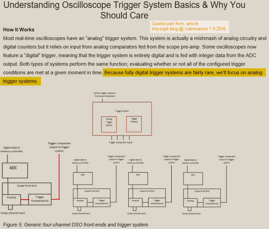
Conventional analog trigger system in some digital oscilloscopes.
In some cases traditional principle is possible to develop also very extremely good as example in some special Teledyne LeCroy models with clever trigger system.
Most simple analog pathway trigger system we can find in some older and/or bottom level digital oscilloscopes like example in Agilent, Tektronix older designs and/or bottom level models, Rigol 1000E, Siglent 1000CNL/CML/DL, Hantek.
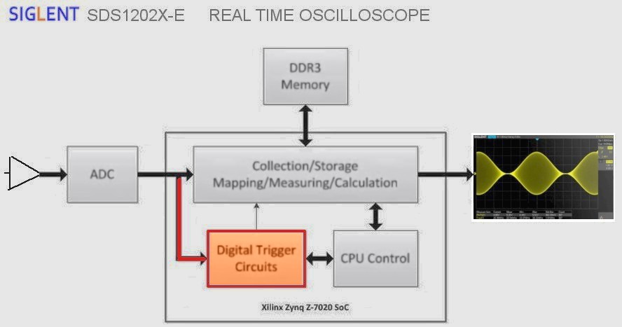
Siglent SDS1000X-E series RTO full digitall side trigger. Sidenote: Because there is one ADC chip internally interleaved for 1GSa/s for one channel mode it can not use for trig from unused main channel without reducing samplerate so there is not this function implemented.
Ext Trig do not have digital trigger system, it use conventional analog pathway with ltrigger comparator circuit. ExtTrig trigger have limited trigger functions and trigger timing quality overall is not at all in same level as trigger from main channel.
Trigger coupling AC (DC Block) 5.8Hz *
Trigger coupling LF reject (Also DC bloc and reduce < 2.08MHz * )
Trigger coupling HF reject (block or reduce > 1.27MHz * ) (also narrow trig hysteresis)
Trigger Noise reject off: normal trig hysteresis, on: wide trig hysteresis.
* limits from user manual version UM0101X-E02B
-
So after installing latest firmware this POS (1202X-E) still locks up!!!
Please try write down as detailed description as possible about how to get it locked/crashed. So detailed that also we and or least Siglent can repeat it.
After I have updated to latest FW I have made some semirandom "monkey tests" and will also continue these randomly and not yet meet any total crash.
-
Siglent SDS1000X-E series RTO full digitall side trigger. Sidenote: Because there is one ADC chip internally interleaved for 1GSa/s for one channel mode it can not use for trig from unused main channel without reducing samplerate so there is not this function implemented.
The most complete specifications available seem to be from the data sheet (latest version):
Ext Trig do not have digital trigger system, it use conventional analog pathway with ltrigger comparator circuit. ExtTrig trigger have limited trigger functions and trigger timing quality overall is not at all in same level as trigger from main channel.
Trigger coupling AC (DC Block) 5.8Hz *
Trigger coupling LF reject (Also DC bloc and reduce < 2.08MHz * )
Trigger coupling HF reject (block or reduce > 1.27MHz * ) (also narrow trig hysteresis)
Trigger Noise reject off: normal trig hysteresis, on: wide trig hysteresis.
* limits from user manual version UM0101X-E02B
Coupling Frequency Response (CH1 ? CH2)
DC: Passes all components of the signal
AC: Blocks DC components and attenuates signals below 8 Hz
LFRJ: Blocks the DC component and attenuates the low-frequency components below 2 MHz
HFRJ: Attenuates the high-frequency components above 1.2 MHz
Coupling Frequency Response (EXT)
DC: Passes all components of the signal
AC: Blocks DC components and attenuates signals below 30 Hz
LFRJ: Blocks the DC component and attenuates the low-frequency components below 10 KHz
HFRJ: Attenuates the high-frequency components above 500 KHz
So definitely different specifications for the different trigger paths, but I'm not certain how the trigger works correctly if it has to use the post-ADC data. Assuming that the AC coupling on the vertical channels takes out the DC component before the trigger system can work with the data (as is implied by the block diagram), there would be no way to set a DC trigger level correctly.
For example, if you had a 6 Vpp sine signal riding on a +3 Vdc offset:- setting DC coupling on the vertical channel passes this to the ADC, then you can set a DC coupled trigger level at +6 V to trigger in the centre of the trace
- setting AC coupling on the vertical channel strips the +3 Vdc offset out before the ADC, so where does the DC coupled trigger 'zero' position start -- presumably ground in an Earth grounded 'scope
It will be interesting to check this behaviour. If the block diagrams are correct, you would expect different 'scopes triggering implemented differently to produce different results. -
So definitely different specifications for the different trigger paths, but I'm not certain how the trigger works correctly if it has to use the post-ADC data. Assuming that the AC coupling on the vertical channels takes out the DC component before the trigger system can work with the data (as is implied by the block diagram), there would be no way to set a DC trigger level correctly.
For example, if you had a 6 Vpp sine signal riding on a +3 Vdc offset:- setting DC coupling on the vertical channel passes this to the ADC, then you can set a DC coupled trigger level at +6 V to trigger in the centre of the trace
- setting AC coupling on the vertical channel strips the +3 Vdc offset out before the ADC, so where does the DC coupled trigger 'zero' position start -- presumably ground in an Earth grounded 'scope
It will be interesting to check this behaviour. If the block diagrams are correct, ....
Block diagram is correct for CH1 and CH2. How many times it need repeat: SDS1202X-E, as also SDS1000X/X+ and as also SDS2000X have full pure digital trigger system so that for trigger there is used only and alone data after ADC. Period. This is not quessing. I KNOW it, exactly. Period.
All these scopes have also External Trig, including also SDS2000X 4 channel models. All these Ext Trig are conventional analog - trigger comparator circuit.
Main channels AC coupling is made using series capasitor soon after channel input connector for total DC block. After then there is nothing what know DC level before this DC block. Not in trigger system and not in main signal system. So it is designed and so it is done.
If just use example.
6Vpp pure sine 1kHz + 3VDC and input coupling AC. DC is blocked and AC part of signal (note freq response) is symmetric between +3V and -3V peak to peak. Trigger setting: Coupling DC and Trig level: 0V. Rising edge.
Trigger point is exactly where signal goes upside crossing vertical zero line. Just as expected and also what is exactly right. It is right because user select that scope hard block DC bias (3Vdc --||-- 0V). Trig is now DC coupled to this signal what it is there after DC block and digitized. Trigger do not need know there is DC blocked. Just as it also do not know if DC is blocked externally.
-
I have an SDS2000X. Is there a quick way to zoom into a DC offset signal with the channel DC coupled?
I have a 3.3V power rail that looks a little noisy that I need to inspect. When I change the V/Div, the DC offset changes. And once you are in 10mV/Div, even the course adjust is much to fine and takes forever to adjust. The "Auto Setup" button gets close, but it takes a long time to operate and always changes my V/Div.
I'd rather the offset stay fixed as I change V/Div. Instead I've resorted to writing SCPI "Zoom In" and "Zoom Out" commands that does this for me and binding them to hotkeys. This really seems like something the scope should do for me.
Is there a reason the V/Offset has to scale with V/Div in a DSO? Why does pushing the "Position" button change to 0V instead of Vmean? -
I have an SDS2000X. Is there a quick way to zoom into a DC offset signal with the channel DC coupled?
This use is the perfect need for use of AC input coupling.
I have a 3.3V power rail that looks a little noisy that I need to inspect. When I change the V/Div, the DC offset changes. And once you are in 10mV/Div, even the course adjust is much to fine and takes forever to adjust. The "Auto Setup" button gets close, but it takes a long time to operate and always changes my V/Div.
I'd rather the offset stay fixed as I change V/Div. Instead I've resorted to writing SCPI "Zoom In" and "Zoom Out" commands that does this for me and binding them to hotkeys. This really seems like something the scope should do for me.
Is there a reason the V/Offset has to scale with V/Div in a DSO? Why does pushing the "Position" button change to 0V instead of Vmean?
There are limitations on the offset available.
From the datasheet (1x probe)
1mV/div ~ 100mV/div: ±1V
102mV/div ~ 1V/div: ±10V
1.02V/div ~ 10V/div: ±100V
Sometimes for closer inspection the supplied 10x probes can be limiting.
Position control push places the 0V reference point on the center graticule, it has no other function.
-
If just use example.
Then there is no difference between AC coupled and DC coupled triggering if the channel is AC coupled. (Which explains the choice about presentation of the trigger level to the user.)
6Vpp pure sine 1kHz + 3VDC and input coupling AC. DC is blocked and AC part of signal (note freq response) is symmetric between +3V and -3V peak to peak. Trigger setting: Coupling DC and Trig level: 0V. Rising edge.
Trigger point is exactly where signal goes upside crossing vertical zero line. Just as expected and also what is exactly right. It is right because user select that scope hard block DC bias (3Vdc --||-- 0V). Trig is now DC coupled to this signal what it is there after DC block and digitized. Trigger do not need know there is DC blocked. Just as it also do not know if DC is blocked externally.
I have read through the user manual and this behaviour isn't explained. Trigger coupling is on page 53 of the user manual (page 71 of the PDF).
It is useful to know exactly what the interactions between the different coupling options produce, so this could be addressed in some examples. (The manual does have significant space devoted to explanation of the serial decoding functions, including trigger interaction, so this isn't an issue of lack of documentation generally.) -
There's a new version for the SDS1202X-E that was released a few days ago:If just use example.
Then there is no difference between AC coupled and DC coupled triggering if the channel is AC coupled. (Which explains the choice about presentation of the trigger level to the user.)
6Vpp pure sine 1kHz + 3VDC and input coupling AC. DC is blocked and AC part of signal (note freq response) is symmetric between +3V and -3V peak to peak. Trigger setting: Coupling DC and Trig level: 0V. Rising edge.
Trigger point is exactly where signal goes upside crossing vertical zero line. Just as expected and also what is exactly right. It is right because user select that scope hard block DC bias (3Vdc --||-- 0V). Trig is now DC coupled to this signal what it is there after DC block and digitized. Trigger do not need know there is DC blocked. Just as it also do not know if DC is blocked externally.
I have read through the user manual and this behaviour isn't explained. Trigger coupling is on page 53 of the user manual (page 71 of the PDF).
It is useful to know exactly what the interactions between the different coupling options produce, so this could be addressed in some examples. (The manual does have significant space devoted to explanation of the serial decoding functions, including trigger interaction, so this isn't an issue of lack of documentation generally.)
http://www.siglentamerica.com/USA_website_2014/Documents/UserManual/SDS1000X-E_UserManul_UM0101E-E02B.pdf
Off to read it.............. -
I have an SDS2000X. Is there a quick way to zoom into a DC offset signal with the channel DC coupled?
I have a 3.3V power rail that looks a little noisy that I need to inspect. When I change the V/Div, the DC offset changes. And once you are in 10mV/Div, even the course adjust is much to fine and takes forever to adjust. The "Auto Setup" button gets close, but it takes a long time to operate and always changes my V/Div.
I'd rather the offset stay fixed as I change V/Div. Instead I've resorted to writing SCPI "Zoom In" and "Zoom Out" commands that does this for me and binding them to hotkeys. This really seems like something the scope should do for me.
Is there a reason the V/Offset has to scale with V/Div in a DSO? Why does pushing the "Position" button change to 0V instead of Vmean?
This is not SDS2000X alone. Also all SDS1000X and X-E.
There is room for make it better for user. User interface NEED develp better for adjusting and set offset V and also how it handle it when V/div setting change. Analog front end itself have hardware what need 3 separate offset range.
Just for example. If I select (SDS1000X) 500uV/div or (SDS2000X) 1mV or 2mV/div and I need adjust maximum offset. I need carefully think do I need this. Because if I really need it, I need first go to lunch and start this adjust after then Because this adjustment takes long time.
When I need do this I feel every time that this programmer do not have any real knowledge and experience in real world with oscilloscopes. Who can teach them? Usually specially designers want themselves intensively study and exercise and develop themselves for better and beter but in this culture it looks like this process is unknown stranger. I do if boss really command and just what he command and thats it. Same in chinese schools. If teacher do not command exactly and directly students do nothing. All look how many cny today but no one do free work for develop better. Perhaps Mahjong is more intersting to win than develop better and better UI for win later in future.
Thumb rule: If I need look DC supply ripple, mostly I use input AC coupling.
But not allways. Some times I use input DC coupling but External DC block with quite low cutoff frequency (more capasitance) for detect some very low frequency noise aka "1/f" noise. Scope input AC coupling frequency response is not good for these special things.
Least I hope Siglent develop this offset setting functions much better. There can be some kind of user settable "fixed" offset, there can be some fast way to adjust it more fast and accurate. Also some "keep offset" when I change V/div is important. But in this case need solve how to do if front end change V band.
Details how it is good can not simply define because also different users have different situations and habits. Also there is just like I like black coffee with real milk but some other like 3 in 1 coffee mix.
Also AutoSetup can be more sophisticated with user settable parameters and ways how it do. Example do only vertical, do only horizontal and so on...
-
Siglent - I have a request. If you insist on having all faults reported for all equipment models in this one thread, PLEASE ask posters to start with the actual Model number they are referring to AT THE TOP OF EVERY POST. I've been catching up on the last few pages and comments are jumping around between different models and it's very confusing. Also, when people answer questions, they should do the same (if they don't quote the post they are responding to) so that you have to go back and read the original post to know what model was being discussed.
Another request; it doesn't help the engineers in China to understand when we insert colloquialisms or abbreviations like POS, if they looked that up they might think it stood for point of sale. The request it to keep it in plain English as much as possible. -
There's a new version for the SDS1202X-E that was released a few days ago:
Yes, my reference above is for the new version.
http://www.siglentamerica.com/USA_website_2014/Documents/UserManual/SDS1000X-E_UserManul_UM0101E-E02B.pdf
Off to read it..............
(I have found a few errors already, too. Mostly references to four-channels.)
For some reason the table of contents ("Table of Content" ) and figures ("Content of Figure"
  ) is poorly formatted again. Why they couldn't spend two minutes to get these aligned with page breaks is a mystery. I don't know if this is typical for Siglent manuals, or if the person working on these is unusually indifferent.
Also, the specifications in the user manual and data sheet concerning trigger coupling don't agree -- refer to the post #830 above.
Hopefully Siglent will get around to producing a service manual with definitive specifications. -
There's a new version for the SDS1202X-E that was released a few days ago:
Yes, my reference above is for the new version.
http://www.siglentamerica.com/USA_website_2014/Documents/UserManual/SDS1000X-E_UserManul_UM0101E-E02B.pdf
Off to read it..............
(I have found a few errors already, too. Mostly references to four-channels.)
For some reason the table of contents ("Table of Content" ) and figures ("Content of Figure" ) is poorly formatted again. Why they couldn't spend two minutes to get these aligned with page breaks is a mystery. I don't know if this is typical for Siglent manuals, or if the person working on these is unusually indifferent.
Also, the specifications in the user manual and data sheet concerning trigger coupling don't agree -- refer to the post #830 above.
Hopefully Siglent will get around to producing a service manual with definitive specifications.
In user manual, example some part of trigger explanation is total mess. Perhaps who writw it do not know anything how it works or how this mess is possible.
Small example:
"Analog channel input: Signals input from analog channels CH1 and CH2 can all be used as the trigger source. No matter whether the input of the channel selected is enabled, the channel can work normally."
or
"The oscilloscope provides 4 kinds of trigger coupling modes:
? DC: allow DC and AC components into the trigger path."
Lot of this kind of things in whole manual. Also some parts are perhaps not at all this model. Some things are perhaps residues from SDS1000 series (CNL/CML/DL/CFL) some things perhaps from SDS2000X models(?) and some, from deep ground or sky perhaps.
But one thing I can predict and "promise". In future we never get manuals like 1960 - 1980 from Hewlett-Packard or original old Tektronix. Never again. This is impossible. One manual costs more than whole lot of example SDS1000X-E scopes. Doing detailed and very deep level manuals is waste of money and waste of time. No one can do this. Take example late 80s Tektronix manual where is deep in curcuit details and explanations how they work and for front panel users detailed descriptions and definitions how things and adjustments exactly works. This era do not come back. It is impossible. No one do not want pay it.
Todau scopes are buy-use-recycle and buy new... pewriod is now perhaps 2 - 4 years. Soon period is more short. Who have time to read even one full set of Tektronix 2465 manual, exactly. every chapter, every detail and also understood these exctly. (of course it can....all things can...but) I do not personally know any.
Also I have still left "truck load" of these old manuals (and equipments). Some manuals I have even never opened. Just collecting dust. Some day I read very deeply one Tek Digital scope manual for find how high resolution exatly work and produce data... it was possible because manual was really perfect and not too many errors in this chapter.
One very important thing is: learn yourself how your equipment works exatly in special situations, exercise..exercise, read free available materials for basic simple or complex things... it is also called.."know your equipment". Use only after this period for any serious real work. Fun play and real works, they are also bit different cases. We can not say RTFM because manuals are - poor or wrong or junk.
Also, good and technically experienced seller can give some short "course" for model detail or basic things what are good to know (if buy from local place where sellers are engineer level and know also more than just price and carton weight and color. -
Quote
DC: allow DC and AC components into the trigger path.
If the DC input selection removes the capacitor from the input then DC and AC components will enter the scope. e.g. if you had a DC trigger set up of +1 V and then input a 3 V pk-pk signal, the positive-going half of the waveform would trigger when it hit the +1V level, what's wrong with that? -
Nothing.QuoteDC: allow DC and AC components into the trigger path.
If the DC input selection removes the capacitor from the input then DC and AC components will enter the scope. e.g. if you had a DC trigger set up of +1 V and then input a 3 V pk-pk signal, the positive-going half of the waveform would trigger when it hit the +1V level, what's wrong with that?
The implication is that for an AC coupled channel, DC trigger coupling is functionally the same as AC trigger coupling. Some functionality gets lost if you perform triggering on the digitised data from the ADC.
(This is functionally the same as taking an analogue trigger from the channel signal path after the blocking capacitor -- it doesn't matter if the trigger coupling is DC or AC if the channel is set to AC coupling.) -
But one thing I can predict and "promise". In future we never get manuals like 1960 - 1980 from Hewlett-Packard or original old Tektronix. Never again. This is impossible. One manual costs more than whole lot of example SDS1000X-E scopes.
Or about one round of drinks at the executives' country club. (Priorities.)
Yes, documentation does take time and effort -- and money -- to produce. That is not an excuse to omit it or do a poor job.QuoteWe can not say RTFM because manuals are - poor or wrong or junk.
Rigol seem to be able to produce better manuals. I see no reason why Siglent can't at least match Rigol.QuoteAlso, good and technically experienced seller can give some short "course" for model detail or basic things what are good to know (if buy from local place where sellers are engineer level and know also more than just price and carton weight and color.
Are you really saying that the reseller / agent should be responsible for effectively documenting what they sell? If so, perhaps you should consider the profit margins on these low-end 'scopes compared to the Tektronix and Keysight price level. -
Quote
Aggree and poor job can not accept. There is also some level in poor job that making better do not cost nearly anything but give job to other person who can do it.But one thing I can predict and "promise". In future we never get manuals like 1960 - 1980 from Hewlett-Packard or original old Tektronix. Never again. This is impossible. One manual costs more than whole lot of example SDS1000X-E scopes.
Or about one round of drinks at the executives' country club. (Priorities.)
Yes, documentation does take time and effort -- and money -- to produce. That is not an excuse to omit it or do a poor job.Quote
Yes I really hope Siglent do better manuals but Rigol must not be any kind of example that should be imitated. Example what try reach must be Siglent own standards what need develop and then reach.QuoteWe can not say RTFM because manuals are - poor or wrong or junk.
Rigol seem to be able to produce better manuals. I see no reason why Siglent can't at least match Rigol.QuoteQuoteAlso, good and technically experienced seller can give some short "course" for model detail or basic things what are good to know (if buy from local place where sellers are engineer level and know also more than just price and carton weight and color.
Are you really saying that the reseller / agent should be responsible for effectively documenting what they sell? If so, perhaps you should consider the profit margins on these low-end 'scopes compared to the Tektronix and Keysight price level.
False. At least a really weird interpretation of what I said. Talking is pretty difficult if every message is twisted.
-
Then you should explain what you meant by that remark, as it appears that you are indeed suggesting that the reseller / agent should make up for the shortcomings in documentation and other support from the manufacturer.Quote from: rf-loopAlso, good and technically experienced seller can give some short "course" for model detail or basic things what are good to know (if buy from local place where sellers are engineer level and know also more than just price and carton weight and color.
Quote from: boggis the catAre you really saying that the reseller / agent should be responsible for effectively documenting what they sell? If so, perhaps you should consider the profit margins on these low-end 'scopes compared to the Tektronix and Keysight price level.
False. At least a really weird interpretation of what I said. Talking is pretty difficult if every message is twisted.
Shifting the burden of support from the manufacturer onto the intermediaries or customer is the biggest problem that these Chinese companies need to resolve. If they made a bit more effort here (and tried to better QA the firmware) they would be perceived as being more equivalent to the 'name brand' manufacturers -- and the cost of this need not be exorbitant. -
Dear SSA3021X staff,
could someone verify the mentioned behavior of the device listed below:
My FW Version is 1.2.8.3
When setting Ref level to 0dBm, scale grid to 1dB and
measuring trace#1 (alias A) switching then via front button
to trace#2 (alias B) and selecting clear trace to start the scan
of the second trace then trace A will be deleted while trace B
plotted.
I observed this behavior only in the 1dB scale factor setting.
When using 10dB scale all looks fine.
Thanks in advance for your explanation.
Markus -
Dear SSA3021X staff,
could someone verify the mentioned behavior of the device listed below:
My FW Version is 1.2.8.3
When setting Ref level to 0dBm, scale grid to 1dB and
measuring trace#1 (alias A) switching then via front button
to trace#2 (alias B) and selecting clear trace to start the scan
of the second trace then trace A will be deleted while trace B
plotted.
I observed this behavior only in the 1dB scale factor setting.
When using 10dB scale all looks fine.
Thanks in advance for your explanation.
Markus
Hello, Markus.
Maybe I am not quite understanding your question correctly but if Trace 1 and Trace 2 are both set to Clear-Write then they are both displaying the same signal. The last trace you select (Trace 2 in this case) will be in front of Trace 1 so it will hide Trace 1. When you change the scale (or RBW or just about any other parameter) the traces will now appear differently so that you can see them both.
For a test, you might use View on one trace and Clear-Write on the second. You should be able to see a slight difference between them.
If I have misunderstood your question, you can contact us at
info@siglent.com
Regards
-
Dear Siglent-Staff,
I will clarify a bit more my concern.
The issue I obserfed occured during the measurement of a 3dB three port power splitter.
I had switch on the TG (-10dBm Level) and connected output of TG to input of SA.
The full span was sweeped and the result was stored into trace A. This was my ref line.
Then I plugged the PS between input and output (TG <-> SA) terminated the remaining
PS port with 50Ohm load and switch to trace B and start a second sweep to see the
difference.
When doing this in the 10dB grid scale mode all went fine, but when doing the same job
in the 1dB grid scale mode, trace A will be deleted while trace B is sweeped.
Hopefully you could verify and observ the mentioned behavior.
Many thanks in advance for your effort and sorry for causing inconvenience if so.
Markus
-
I made 3 measurements using TG
First trace A circuit between TG out SA in then lock trace using view
then trace B small chance in circuit and as trace A
then trace C again small change and running when take image.
works just normally, as designed and without any problems
So if there is some problem you need explain it more detailed, exactly including all things, so that it can repeat.
Can you make test so that first with normalization using very short cable 1. and use 95% NormRefPos setting so that trace is not top border. After then do not change level settings or frequency settings!
Then do this same test so that circuit between TG and SA input is just cable 2. and save trace A (view). Next test with trace, B, with cable 3.
Trace A disappear?
-
Dears,
thanks for your verification and effort.
I will do some tests with screenshots attached and a more detailed
step by step discription tonight and will post my results a.s.a.p.
Bye
Markus -
Dear Staff,
I had verified the mentioned behavior today again.
I will summrize my observations again.
See attached Pictures.
A: action / P: picture
A1: TG=0dBm / scale=1db / ref=3dBm / Sweep single / Trace button pressed / trace A selected / Clear Write
P1: Trace A was sweeped and frozen on the screen.
A2: trace B selected / inserted DUT between TG and SA
P2: Trace A label changed to Trace B only
A3: Clear Write selected
P3: while trace B is printed trace A will be deleted (was my first impression)
But what I found today is that Trace A is shifted/hidden behind Trace B and if I press
Blank softkey the trace B will be deleted and just behind trace B that overlaped trace A
the trace A occure again but at the positionof trace B.
Hopfully you could now reproduce my observation.
Markus