Author Topic: #562 – Electroboom!  (Read 111450 times)

0 Members and 3 Guests are viewing this topic.

Offline bdunham7

  • Super Contributor
  • ***
  • Posts: 7902
  • Country: us
Re: #562 – Electroboom!
« Reply #225 on: November 14, 2021, 03:53:25 am »
Can I blame the tequila?

You may.

Quote
What I am perplexed about is your fixation with 'where there are no fields'. If the charges are there, there is at least their field, so you can't do away with it. If there are no fields to push and keep them there, then the charges are no reason to accumulate there.

A very good point, one which occurred to me several hours ago as I was writing another response.  I'm going to have to be very careful how I state the case, but it isn't fatal to the concept that I'm trying to get across or at least I don't think so yet.

Quote
I am not going to touch the motional case even with a ten foot pole. We are already wasting too much space and time to address the Lewin ring and we would fall down a relativistic rabbit hole with no end. I suggest you look up Purcell for an introduction to that kind of stuff.

OK, it's a sideshow anyway.  But can you have a glance at my last diagram in my reply to bfseechannel and see what you think the electroscopes would show at A, B, C and D in that case?

I'll try to read and digest the rest of what you wrote tomorrow.  I don't think it is a waste of space or time if it advances anyone's understanding (mine, for example) as opposed to degenerating into a food fight.
A 3.5 digit 4.5 digit 5 digit 5.5 digit 6.5 digit 7.5 digit DMM is good enough for most people.
 

Offline Sredni

  • Frequent Contributor
  • **
  • Posts: 746
  • Country: aq
Re: #562 – Electroboom!
« Reply #226 on: November 14, 2021, 04:15:01 am »
I can answer for a ring of finite dimensions, where the fields are nonzero.
In general, unless the ring is perfectly circular and isotropic - without gaps and localized resistors - the symmetry is broken and surface charge will show up not only at the terminals of a gap (or at the discontinuities when the copper becomes the highly resistive material of a resistor) but also on the lateral surface. So, there will be in general be charge on the conductor even in that position because the coloumbian field has to compensate the perfectly rotating Eind field in the conductor.

The amount of surface charge necessary to do this is in general unbelievably small. With ordinary circuits it can be just a handful of electron charges! Therefore, while the charge would be there on the surface, I seriously doubt it could be measured with a leaf electrometer, or any electrometer that will interact with the field.

And if you make the ring so big that the field becomes negligible you are only making matters worse.
Jefimenko, for lumpled circuits in DC, had to use high voltage generators to get pictures of the electric field in the space between the conductors.

Obviously it is implied that you use perfect conductors with zero resistivity, but you need to clarify this concept of vanishing field.
In reality, for a ring big enough the resistance of the ring would make the current so small that you won't be able to see anything at all, even at the terminals (imagine a ring one light yeat in radius from Lewin's solenoid).
All instruments lie. Usually on the bench.
 

Offline bdunham7

  • Super Contributor
  • ***
  • Posts: 7902
  • Country: us
Re: #562 – Electroboom!
« Reply #227 on: November 14, 2021, 04:40:38 am »
In reality, for a ring big enough the resistance of the ring would make the current so small that you won't be able to see anything at all, even at the terminals (imagine a ring one light yeat in radius from Lewin's solenoid).

OK, fair enough.  I wasn't specific about my 'negligible fields' or the length of the wire.  For concentric rings, Faraday's law dictates that all of the rings have the same total EMF Eind so you can think of that as volts per radian--if the total EMF Eind is 1 volt, there are 1/(2 * pi) volts/radian. If I've flubbed that, well..Scotch.

I'm only thinking of a few meters of wire and while there still will be a circular field that only diminishes with the radius, I can arrange the wire and electroscope to be as perpendicular to those fields as possible so they have minimal effect.  I think I only need them to diminish to small fraction of the field near the ring.  If I want to try them in positions that are 20 degrees apart on the ring, as long as the entire apparatus stays within a 1 degree arc of the perpendicular line, I have at most a 5% error due to the external field at the electroscope.  As for the sensitivity of the electroscopes, these are theoretical electroscopes, so assume they have a minimum sensitivity of a small fraction of the total ring EMF.
A 3.5 digit 4.5 digit 5 digit 5.5 digit 6.5 digit 7.5 digit DMM is good enough for most people.
 

Offline Sredni

  • Frequent Contributor
  • **
  • Posts: 746
  • Country: aq
Re: #562 – Electroboom!
« Reply #228 on: November 14, 2021, 05:11:30 am »
The reason you always link the same EMF, which is the circulation of the Eind field on a closed path when the ring is not there, is that outside of the the circular solenoid the Eind field decreases with 1/r, while the perimeter of the region of space you will be putting your circular ring will increase with r. The magnitude of the Eind field along a circle is constant. So when you integrate on a bigger ring, you have a smaller field Eind but a bigger path that compensate each other to give the same value for the EMF. In principle, you will link the same EMF even at 10 light years.

Let's see: 1V EMF at 10 cm radius means and electric field Eind of 1V/(2 pi 0.1m) = 1.59 V/m
Let's make the ring 1 m of radius and the Eind field becomes 0.159 V/m.
At 10 m it will be 15 mV per meter.

But that field Eind will no longer be there once you put your copper ring with the resistors in the circular path of radius 10cm or 1m or 10m. It will be cancelled by and equal and opposite electric field generated by the charges that it initially displaced and after a handful of nanoseconds have crammed up (for the most part) at the interfaces with the resistors. 
These charges will build up the field inside the resistors and that is why sometimes Lewin said that all the emf shows up at the resistors: you have 1V along the whole circle, and nearly 0.9V appears where the 900 ohm resistor is, and nearly 0.1V appears where the 100 ohm resistor is. In the wire there is cancellation and all that is left in copper is of the order of the millivolt (corresponding to a field of some tens of microvolt per meter.)
EDIT: and then near the ring you will still see a distorted induced field that will interfere with your instrument.

Some residual charge will be also present on the surface of the conductor to steer the compensating field, but as I said, I would not expect anything you could measure with a leaf electrometer. It might be interesting, but not easy, to compute the density of charge on the lateral surface but to what end?
« Last Edit: November 14, 2021, 05:33:46 am by Sredni »
All instruments lie. Usually on the bench.
 

Offline Sredni

  • Frequent Contributor
  • **
  • Posts: 746
  • Country: aq
Re: #562 – Electroboom!
« Reply #229 on: November 14, 2021, 03:05:32 pm »
I don't think it is a waste of space or time if it advances anyone's understanding (mine, for example) as opposed to degenerating into a food fight.

This is the only post I'll made related to the motional case. And it's a silent one.


https://i.postimg.cc/m2QQ0KYk/Conservativs-vs-Rotational-vs-Motional-small.png
All instruments lie. Usually on the bench.
 

Offline rfeecs

  • Frequent Contributor
  • **
  • Posts: 807
  • Country: us
Re: #562 – Electroboom!
« Reply #230 on: November 14, 2021, 05:53:42 pm »
I'm only thinking of a few meters of wire and while there still will be a circular field that only diminishes with the radius

Your forgetting that the core is a toroid.  Looking at the cross section view, there are two cores.  So as you move away there are two sets of fields that rapidly cancel.

Another thought experiment would be to spit the wire in the middle, move it out of the field and then join it back together.  Then you can look at the coulomb potential only.

Or you can think of the E and B fields and the charge and current as the only primary quantities that matter; and consider the potentials as just mathematical conveniences.
 

Offline Sredni

  • Frequent Contributor
  • **
  • Posts: 746
  • Country: aq
Re: #562 – Electroboom!
« Reply #231 on: November 14, 2021, 07:14:40 pm »
Your forgetting that the core is a toroid. 

You're right. I keep bringing up the infinite solenoid to exploit the symmetry and the simple analytical expression of the field.  I think we should all stick with that to make things simpler and consider the toroid as a "poor man's folded infinite solenoid" for lab experiments with voltages and currents in the ring.
All instruments lie. Usually on the bench.
 

Offline Jesse Gordon

  • Regular Contributor
  • *
  • Posts: 126
  • Country: us
Re: #562 – Electroboom!
« Reply #232 on: November 15, 2021, 08:54:30 pm »
Your forgetting that the core is a toroid. 

You're right. I keep bringing up the infinite solenoid to exploit the symmetry and the simple analytical expression of the field.  I think we should all stick with that to make things simpler and consider the toroid as a "poor man's folded infinite solenoid" for lab experiments with voltages and currents in the ring.

The difficulty with the toroid is that the folded nature makes some hands-on experimental observations difficult.

For smallbrains like me, we need simple observable reality or we don't feel it's real.

I am, however, sorely tempted to use a carbide or diamond bit to drill a small hole in the side of a formerly toroidal core to facilitate such measurements  :-DD :-DD :-DD
 

Offline bsfeechannelTopic starter

  • Super Contributor
  • ***
  • Posts: 1667
  • Country: 00
Re: #562 – Electroboom!
« Reply #233 on: November 15, 2021, 09:23:47 pm »
Helmholtz is your friend.
 

Offline Jesse Gordon

  • Regular Contributor
  • *
  • Posts: 126
  • Country: us
Re: #562 – Electroboom!
« Reply #234 on: November 15, 2021, 10:05:36 pm »
It isn't "just two resistors and nothing else", it has a closed loop of wire in a varying magnetic field. It has a transformer (as has been pointed out over and over here). If the model doesn't include the transformer, it is an incomplete model.

What transformer? Replace the solenoid by a moving magnet, or by the radiation coming from a radio station. The voltages in your circuit will not add up to zero. This was not only proven theoretically but practically. It is the principle behind the reception of every radio.

And we're not discussing the model. We are discussing if it is possible to measure two different voltages at the same two points by the same or different but identical meters on a circuit subjected to an externally generated varying magnetic field.

It is. Period.

What transformer? The transformer that is there. What is a transformer? Two coils with a coupled field. It is a circuit element. If you neglect a circuit element in a circuit diagram, it is incorrect. It is no more of an error than if there was a AC (or DC) source in the loop and you neglect to put it in the circuit diagram. It is obvious that this tread isn't going to convince anyone of anything.

Indeed sir! This entire topic has me baffled.

Folks have argued so strongly that KVL cannot work in Lewin's circuit.

Dr. McDonald said "Lewin's circuit is within the range of applicability of Kirchhoff's loop equations, which can be used to predict measurements by the 'voltmeters' in the experiment. "

Dr. Belcher cited Feynman and said "In this sense, KVL holds, as argued by Mehdi Sadaghdar ..."

So at a very least, we ALL ought to be able to see that it is a very complex topic and not even MIT/Princeton physics professors agree on it.

(However, I do note that the two who said "Mehdi is right" are thoughtful meticulous individuals who did some research to come to their conclusion, whereas Dr. Lewin just dismissed any questions out of hand and stuff.  If I was going purely on the odds, Belcher & McDonald would be much more likely to be right because they are willing to question their assumptions and sort through things.)

I'm with Dr. McDonald and Dr. Belcher.

As for me, I have no degrees and am no math wiz. But I have a volt meter and scopes and stuff, and feel like I understand the basics of EE. When I watch Lewin's lectures (and other physics lectures) it all makes sense. But when he did the thing with the Lewin Loop, it seemed odd. So I measured.

As a ham radio guy, I know there are cases where KVL does not hold, or at least it's difficult to measure, because of the non-finite speed of light.
(i.e. when your volt meter leads become feed lines, you then have to look at the propagation, and two voltages may not arrive at the correct time, so a phase shift may give the appearance of voltages not adding up. However, I'll give 100 fresh never used blank pixels (the picture element kind) to the first person who can present me ANY scenario for which the best and proper application of KVL fails.)

But in cases where the basic laws tell us how we can unambiguously probe, and where the wavelength far exceeds the size of our apparatus, KVL seems to hold so far as I have measured.

What baffles me is that all kinds of people crop up to argue, but I'm not even sure what they are arguing. I'm not sure they know what they are arguing.

Usually, when I have a disagreement with someone, it's not too long before I understand where I went wrong, or they understand where they went wrong.

But in this case, even after months of discussion with very intelligent people, none have been able to actually put into words something that helps me see where I've gone wrong, if such is the case.

I almost feel like it's some vague technicality that nobody can put their hands on.

And it's obviously a subtle point, because even Dr. McDonald and Dr. Belcher disagreed with the Master Lewin.

One interesting clue is that over the course of my discussion with various people, we would each make contradictory predictions about real-world measurements, so I would build a contraption to measure it, and my predictions were right each time. So this shows that the people arguing against KVL did not have a full understanding, or they would have predicted correctly. But the fact that their predictions were wrong didn't phase them, so I don't know what to say.

I also find it odd how many strange assumptions seem to be made. Nobody seems to know that resistors, capacitors, and inductors all have resistance, capacitance, and inductance (excepting of course super conductors.)

I find it odd that people seem to think that all voltage drop must be purely ohmic. It's almost like there are two definitions for voltage - one being the kind that a volt meter reads, and another kind that differs from what a volt meter reads - but by now somebody should have said "Hey Jesse, problem is you're using a volt meter. That's not the volts we're talking about...."

I also find it odd that so many people call it a measurement when there is an undocumented error offset added to the "measurement." When you have two unknowns, you are not measuring either of them.

As for me, so far no body has actually shown how Lewin's loop breaks KVL, except by putting undocumented secondary windings in series with the volt meter leads. Doh.

One very kind and sincere fellow and I had a very long discussion on it. At one point I basically said "So if Lewin can fail KVL with undocumented probe paths, then let's see how MaxEQ handles the same thing. I'll tell you the volts per turn, and I will tell you that the volt meter will be on the LEFT side of my solenoid, but, like Lewin, I will not tell you the locations  or path of my probe leads, and you can calculate the voltage I will read.." He couldn't, so I guess MaxEQ fails too?

The fact is, that all measurements fail when you have an unknown variable offset error inline with your meter.

And I have asked so many of them "What about a regular iron core transformer, can it's outputs be used in a loop and have KVL hold?" it is very hard getting them to answer that. Obviously the output of a regular iron core transformer will behave the same as a pair of DDS waveform generators making the same waveform.

I really wish the people who say that KVL fails Lewin could put it into simple words that I could understand.

They say that the measured voltage is path dependent. But if the probes follow a path that prevents or cancels induced voltage, then it's the same as if the magnetic field were contained entirely within the lumped component.


 :-// And after all this, not one correctly lumped correctly probed working model has been presented which shows KVL to fail. I say it's high time. :-//

And after all, KVL does require lumped components. *always*. It cannot be decried as having failed when it's not even KVL that is being tried. If you made a KVL loop out of open wire wound resistors, but instead of measuring voltages always at the ends of the resistors you measured at random locations inside the resistor, of course KVL will fail, even on a DC circuit - but it's not KVL that failed, it was the lumping that failed, it's only a strawman argument.

MaxEQ also fails if you don't model reality. All of physics fails if it's not modeling reality.

Thus I ask myself, what exactly is the actual question at hand?
 

Offline Sredni

  • Frequent Contributor
  • **
  • Posts: 746
  • Country: aq
Re: #562 – Electroboom!
« Reply #235 on: November 15, 2021, 10:06:35 pm »
The difficulty with the toroid is that the folded nature makes some hands-on experimental observations difficult.

How so? I have seen this experiment done on toroidal transformers (MIT), and even on EI transformers (Sam Ben-Yaakov, Ben Gurion University). The EI are 'doubly folded': you just need to be careful not to enclose the 'legs' where the flux in your measurement loop.

Quote
I am, however, sorely tempted to use a carbide or diamond bit to drill a small hole in the side of a formerly toroidal core to facilitate such measurements  :-DD :-DD :-DD

Why on earth would you want to do that? You need to avoid the magnetic flux region.
Please explain.
All instruments lie. Usually on the bench.
 

Offline Jesse Gordon

  • Regular Contributor
  • *
  • Posts: 126
  • Country: us
Re: #562 – Electroboom!
« Reply #236 on: November 15, 2021, 10:42:03 pm »
...
But you probably won't find many confutations in the comments section, because Duhamel, like fromjesse, delete the comments that tell them they are wrong and why. For example, in his last video "Voltage in a loop is weird", a post by Silicon Soup stating that by putting the probes inside the magnetic region a voltage was induced in the loop has disappeared.

Here's the reason:

https://i.postimg.cc/vZ6BM4Wn/screenshot-3.png
...

Just to set the record straight, your statement is false.

Neither I nor Duhamel delete comments just because they disagree with us.

I don't know whether Bob deleted any specific comments, but I don't recall deleting any specific comments, but what I did do is ban ONE particular person (felinus retardus) who was being insulting to my viewers as well as myself. I did not delete all of his comments, if you go look they are still there. In fact, I see his comments on Bob's videos right now and goodness knows his comments are all over my videos right now, as well as comments from other people who disagree with me.

In fact, if you look at my videos on this topic, the bulk of the comments ARE from people who disagree with me, and their comments are still all there.

Neither Bob nor I delete comments just because they disagree with us.

But that one user that you ask about is just mean -- and that's why I banned them(?) and that's why Bob banned him, because he was doing the same thing there.

I actually unbanned felinus retardus at one time and he immediately started up with the insults again, so I banned him again. That interchange is still public as well.

So please, don't accuse us of that, especially when you can literally look at the video comments and see lots of people disagreeing, including comments going back nearly to the upload date in the case of my videos.

Let's try to figure out the issue. Obviously there are very sincere people on all sides of this, trying to make sense of it.

If it was a simple matter and only pure idiots like me got confused by it, then Professor Dr. Kirk McDonald PhD of Princeton wouldn't say IN WRITING "Lewin's circuit is within the range of applicability of Kirchhoff's loop equations, which can be used to predict measurements by the 'voltmeters' in the experiment. "

And Professor Dr.  John W. Belcher PhD of MIT wouldn't cite Feynman and then say IN WRITING "In this sense, KVL holds, as argued by Mehdi Sadaghdar ..."

Perhaps show some patience for those you disagree with?

Thank you.
 

Offline Jesse Gordon

  • Regular Contributor
  • *
  • Posts: 126
  • Country: us
Re: #562 – Electroboom!
« Reply #237 on: November 15, 2021, 10:53:01 pm »
The difficulty with the toroid is that the folded nature makes some hands-on experimental observations difficult.

How so? I have seen this experiment done on toroidal transformers (MIT), and even on EI transformers (Sam Ben-Yaakov, Ben Gurion University). The EI are 'doubly folded': you just need to be careful not to enclose the 'legs' where the flux in your measurement loop.

Quote
I am, however, sorely tempted to use a carbide or diamond bit to drill a small hole in the side of a formerly toroidal core to facilitate such measurements  :-DD :-DD :-DD

Why on earth would you want to do that? You need to avoid the magnetic flux region.
Please explain.


Let's start at a very simple place where my small brain gets it. Ok?

Let's say I have two small but powerful battery operated optically synchronized DDS waveform generators each generating a 60Hz 100mV AC RMS sinewave.
Further, let's say I have a 100 ohm resistor and a 1000 ohm resistor and I use these four components to form a series loop, alternating resistors and DDS units.

If I take a four channel fully isolated input scope and connect each of my four elements to their own scope input with positive-clockwise polarity, will the sum be zero? Let's say I turn on the math channel on the scope, and sum all the inputs, will it be a straight line?

KVL will hold fine in this case, right?
 

Offline Jesse Gordon

  • Regular Contributor
  • *
  • Posts: 126
  • Country: us
Re: #562 – Electroboom!
« Reply #238 on: November 15, 2021, 11:07:36 pm »
...
PS: this would be a brilliant experiment: Use a split core with different permeability in each of the toroids, so that the flux is no longer evenly split. I wonder if the voltages would still add up ;)

Thank you for the invite here my friend!

And yes, the two toroids are slightly different from eachother. They actually really are two toroids in this particular transformer, each made from a looong strip of sheet metal wound up, and there are two of them in there, butted up.

And evidently, one has a little more iron to it because it has more voltage across it.

But regardless, the sum still adds up to "zero." (within the resolution limitation of my volt meter.)

However, if you would like, I would be glad to do an experiment literally with two different toroids which are of significantly different sizes, and do the same test to show you that even then, all the voltages add up to zero going clockwise around the loop.

Would that be meaningful to you? Do you think the voltage would no longer add up to zero?
 

Offline Sredni

  • Frequent Contributor
  • **
  • Posts: 746
  • Country: aq
Re: #562 – Electroboom!
« Reply #239 on: November 16, 2021, 01:46:28 am »
Ok, let's set the record straight. This will be my last post on the topic of your disappearing comments and Bob's merry deletions, but I really need to set the record actually straight.

...
But you probably won't find many confutations in the comments section, because Duhamel, like fromjesse, delete the comments that tell them they are wrong and why. For example, in his last video "Voltage in a loop is weird", a post by Silicon Soup stating that by putting the probes inside the magnetic region a voltage was induced in the loop has disappeared.

Here's the reason:

https://i.postimg.cc/vZ6BM4Wn/screenshot-3.png
...
Just to set the record straight, your statement is false.
Neither I nor Duhamel delete comments just because they disagree with us.
I don't know whether Bob deleted any specific comments,

You literally contradicted yourself from one sentence to the other.
Sentence two says "Duhamel does not delete comments because..."
Sentence three says "I do not know whether Bob deleted any specific comments..."
Did you talk to Bob expressely about this? Sentence three says you didn't. Also says you seem fine about talking of what you do not know.

Record straightened: I can recall at least three posts that disappeared from RSD A. videos. One is the comment from Silicon Soup, stating that by running the probes in the magnetic flux region he was intercepting flux and this inducing a voltage. It was deleted along with a timestamped comment by Copernico Felinis (or, by using your non-insulting name: felinus retardus). Another one is a comment of I believe Mick Vall (Or Mark Fruchtman, a name like that... M---- --a---) where he told Bob that he was wrong and he should not be teaching this wrong concepts because it would cause confusion in students (and he also explained why and where he was wrong). The whole thread disappeared, along with other comments discussing technicalities.
So, keep your "false" to you.
And then there is that exchange with Mr. Anderson. It tells all you need to know.

Quote
but I don't recall deleting any specific comments, but what I did do is ban ONE particular person (felinus retardus) who was being insulting to my viewers as well as myself. I did not delete all of his comments,
But you did not publish some?

I guess that, regarding the insults, you meant comments like this one  - in that case I can understand


Source: your channel - image here https://i.postimg.cc/N081Kppk/screenshot-fromjesse-insults.png

Oh, my bad. That was Samuel Snerden cold open post and he was talking about Lewin. Did you ban him as well, for insulting your viewers? But of course not. Lewin is certainly not a viewer of yours.
Also about insults, and then I'll drop it definitively: I have been through the exchange you are having with ThinkFat. In just two or three comments you manage to call bsfeechannell: "clueless", "totally idiotic", "either he's fulla BS or he's not being honest", "your hero the ignorant bsfeechannel", "he's either ignorant or disingeneous".

Apart from that thing about pots and kettles, I don't think your ban was motivated by insults. You seem pretty comfortable with insults in your channel. I believe it's something else. I wonder what that could be.  :-//
Maybe when you are cornered, you get insecure?

Quote
Let's try to figure out the issue.

Will you start insulting people in here, as well?
If not, I can try to explain what is wrong with what you believe.
Namely:

1. That sentence of Belcher is about the RLC lumped circuit of section 10. Read pages 15 and 16. It's not about the unlumpable Lewin ring.

2. The note of McDonald (it's not a paper, it's a note for his students) has been through many revisions, so you should also specify the date it was last updated. The most recent I have on my laptop says November 14, 2018. And he uses a definition of "voltage drop" that 'others' (namely the IEC) call 'scalar potential difference'. Therefore he is talking about the component of the voltage that is solely determined by the conservative electric field generated by the distribution of charge displaced by Eind. It's just that, and he says so on page 10, after formula (35). The scalar PD alone is insufficient to describe the physical system. In fact, you cannot even apply Ohm's law to that 'voltage drop' as he calls it. And he acknowledges that voltmeters do not measure that 'voltage drop' of his, but the path integral of the total electric field Etot (as Belcher says, as well).
Therefore, when stores will sell AC voltmeters that can read that scalar potential difference, that definition of his will come very handy. Till then, a lot of people prefer to use actual voltage, the one that can be measured by voltmeters and that is path-dependent. It is also much easier to treat.

3. By reading your thread with ThinkFat for the video "The Lewin loop inside an iron core - KVL still holds" it appears to me you have problems with basic electromagnetism. You say con can "correctly lump" the circuit, but Lewin's ring is not lumpable. You also seem to think that if your "volt meter leads do not cut through any changing magnetic fields [...], according to Faraday's law [...] there will be no voltage induced along my volt meter leads".
Do you really think that in order to induce a voltage, the conductors need to pass through the variable magnetic field region?
Is that the reason you want to drill a hole into the toroidal core?
You also seem anxious about looking inside a transformer. But that is the crux of the problem: Lewin's ring has placed two resistor inside the coil of a single turn transformer, creating a circuit that cannot be model with a lumped component.
« Last Edit: November 16, 2021, 01:57:37 am by Sredni »
All instruments lie. Usually on the bench.
 

Offline bsfeechannelTopic starter

  • Super Contributor
  • ***
  • Posts: 1667
  • Country: 00
Re: #562 – Electroboom!
« Reply #240 on: November 16, 2021, 02:13:37 am »
Dr. McDonald said "Lewin's circuit is within the range of applicability of Kirchhoff's loop equations, which can be used to predict measurements by the 'voltmeters' in the experiment. "

You said you have no degrees and you're no math wiz. Probably you didn't read the entire paper by McDonald, or if you did, you didn't understand it.

What he says is that, specifically for Lewin's circuit, it is possible to consider the EMF as a generator element of an equivalent circuit and still apply KVL EQUATIONS. Which is true.

But he stresses that this EMF is nowhere to be found with voltmeters in the circuit.

In Lewin’s example, the magnetic flux in the primary solenoid may well be within a small coil, but the secondary consists of only a single “turn”, so the associated inductive EMF is not well localized, but rather is distributed around the entire secondary loop. Then, since inductive EMF’s are associated with a vector potential, rather than a scalar potential, it can be misleading to interpret the inductive EMF as related to a “voltage”.

Lewin's beef is that people read that you can use KVL EQUATIONS to calculate the voltage across the resistors and try to find this EMF with voltmeters. You'll never find it. People say that the voltages are in the wires. McDonald denies that. It's all over the circuit, and it is not a voltage. So voltmeters won't measure it. (In other words, this circuit is "unlumpable", and modeling it so as to make KVL work is just a math trick).

MacDonald says more.

Kirchhoff’s (extended) loop equation (1) does not apply to all possible circuits, and gives a poor description of circuits whose size is not small compared to relevant wavelengths, in which effects of radiation and retardation can be important. Examples such as Lewin’s in which the self inductance of the entire loop could be important must be treated with care.

So Kirchhoff's law doesn't always hold, does it?

He calculates and confirm that the two voltmeters in Lewin's experiment will show two different voltages even though connected to the same points in the circuit and then declares:

These results were validated by experiment during Lewin’s lecture demonstration.

Quote
"In this sense, KVL holds, as argued by Mehdi Sadaghdar ..."

In what sense? Have you read the whole paper? He explicitly said that the voltage through an inductor is zero. Of course it is! It's just a piece of wire! But across the terminals of the inductor it is defined by its inductance (path dependence of voltage). And IN THIS SENSE, KVL holds. Which is true.

And here we come to the Mehdi problem.

Mehdi claims that KVL ALWAYS holds. Which is not true. He claims that Belcher agrees with him. He doesn't. Belcher says KVL only holds for specific conditions. He says that Lewin is wrong and invokes McDonald. MacDonald doesn't say Lewin is wrong anywhere in his paper. His argument is because he thinks that Lewin presented his circuit as a paradox that cannot be solved in the confines of Kirchhoff's equations. He shows it actually can. But in fact there's no paradox--that's Lewin's argument--when you realize the circuit is immersed in a non-conservative field, which is a much broader concept, that allows you to understand the problems to which McDonald says Kirchhoff's equations can't be applied.

Mehdi claims the voltages are in the wires, that Lewin doesn't know how to probe his circuit and many other irrational and nonfactual assertions. We just can't accept that.

« Last Edit: November 16, 2021, 04:57:10 am by bsfeechannel »
 

Offline bdunham7

  • Super Contributor
  • ***
  • Posts: 7902
  • Country: us
Re: #562 – Electroboom!
« Reply #241 on: November 16, 2021, 02:32:43 am »
Therefore, when stores will sell AC voltmeters that can read that scalar potential difference, that definition of his will come very handy. Till then, a lot of people prefer to use actual voltage, the one that can be measured by voltmeters and that is path-dependent. It is also much easier to treat.

I haven't time for a long post as I sip my Scotch and fix some power sensors but I have two observations.  The first is that in fact the vast majority of times that a voltmeter is used, the user is indeed attempting to measure that 'scalar potential' and would regard any electric fields along the path that are attributable to any other cause to be 'interference'.  And there are a lot of ways of dealing with interference.  I would say that most of the KVLer/YouTubers attempts are exactly that--an attempt to find a path where that circular electric field has zero net contribution.  Mathematically it seems obvious that in-plane without any sort of shielding--has anyone tried shielding?--with a uniform circular field, such a path does not exist.  But in the real world, we usually actually do find such a path, when we can't things gets interesting. 

Quote
creating a circuit that cannot be model with a lumped component.

Second, you can lump it just fine--around the loop you  have two arbitrarily small resistors with -0.9 and -0.1 volts and two semicircles of wire with 0.5 volts each, with the caveat that in the planar paper universe that the problem exists, there is a circular electric field about the center of the loop that corresponds to 1/360 volts per radian, and thus any attempt to measure voltage with a normal voltmeter with test leads will result in 'interference' of 1/360 volts per degree of difference in the radial position of the two test lead ends.  You may not agree with that way of thinking and you may even be right, but the model still works.

Now I'd also like to point out that if you did not know the total loop EMF, I'm quite sure you would be using a KVL-like method of determining it.  You would measure the voltage across the arbitrarily small resistors  (no E * dL, no 'interference', measuring only the scalar potential across the resistor), add those up KVL-style and then assume, correctly of course, that the total EMF Eindon the loop is equal to that.  So instead of the two semicircular wires with 0.5V, you have KVL + superimposition, meaning superimposition of the EMF Eind.  (-0.9 - 0.1 + 1 = 0). 


« Last Edit: November 16, 2021, 02:53:26 am by bdunham7 »
A 3.5 digit 4.5 digit 5 digit 5.5 digit 6.5 digit 7.5 digit DMM is good enough for most people.
 

Offline bdunham7

  • Super Contributor
  • ***
  • Posts: 7902
  • Country: us
Re: #562 – Electroboom!
« Reply #242 on: November 16, 2021, 02:52:00 am »
It's all over the circuit, and it is not a voltage. So voltmeters won't measure it.

It is all over the circuit, but as for it not being a voltage that is a very confusing, very unhelpful and vast oversimplification.  The reason a voltmeter won't measure it is simply because in the problem as drawn, there is no way to connect test leads without getting an exactly equal Eind in the test leads as you have in the wire.  If a path existed without that issue, you could measure the voltage from Ecoul directly.  Note that I am not making any statement here about the existence of such a path.  Your insistence on only full turns is simply the same assertion, only allowing that for exact full turns, there is such a path.

Quote
He calculates and confirm that the two voltmeters in Lewin's experiment will show two different voltages even though connected to the same points in the circuit...

The reason for that is the presence (not absence, as has been asserted elsewhere) of dB/dt in the measuring loop.  The way Lewin presented this confused me and many other people, and that is probably the main reason people are all upset and call him a fraud.  His whole demonstration is designed to provoke rather than explain, IMO--although I can't say whether that is good or bad.

Quote
And here we come to the Mehdi problem.

I haven't watched, but I suppose he didn't clear anything up?  SiliconSoup's presentation was much more helpful although I still think it is possible to think about the problem somewhat differently and still not be 'wrong'.
A 3.5 digit 4.5 digit 5 digit 5.5 digit 6.5 digit 7.5 digit DMM is good enough for most people.
 

Offline Sredni

  • Frequent Contributor
  • **
  • Posts: 746
  • Country: aq
Re: #562 – Electroboom!
« Reply #243 on: November 16, 2021, 03:00:49 am »
in fact the vast majority of times that a voltmeter is used, the user is indeed attempting to measure that 'scalar potential' and would regard any electric fields along the path that are attributable to any other cause to be 'interference'. 

In general that's the spirit.  And in fact, all you need to make sure in order for the voltage shown by your voltmeter to be the same as the voltage 'along' (and very often 'across') the branch of circuit you are probing, is making sure there are no variable magnetic fields in your measuring loop - the one including said branch.
That is why the voltmeters outside the ring measure correctly the voltages along (and across for any path that does not run around the core) the branch with the nearest resistor.
The other measurement loop is marred with an 'interfering voltage' of the EMF of one full turn.

Quote
And there are a lot of ways of dealing with interference.  I would say that most of the KVLer/YouTubers attempts are exactly that--an attempt to find a path where that circular electric field has zero net contribution.

I am well aware of that: they are trying to strip the contribute of the Eind field to only get the contribute of the Ecoul field alone, as if the displaced charge was held in place (instant after instant) by nails, or some superglue. The conservative Ecoul gives a path integral that admit a potential function, what we call scalar potential difference. It is not path dependent and you can apply your KSPDL to that, if it makes you happy.
But removing ALL contributes of Eind means you are no longer considering the physical system in its entirety: the Eind is what makes the charge accumulate in the ring, and along with Ecoul makes the current flow in the ring. It's not like avoiding external, spurious, unwanted, interference from your measurement loop. It's removing the juice that makes your circuit tick.

Decomposing Etot into Ecoul and Eind - and then considering the respective electric scalar potential phi and magnetic vector potential A is nothing new under the sun (it's the Helmoltz decomposition of a vector field into irrotational and solenoidal parts). But your system requires both these fields (or their associated potentials)  to be described. It's fine if you know what you are doing, but pretending the scalar potential difference is the actual voltage (integral of E.dl) is misleading to say the least.

Quote
Quote
creating a circuit that cannot be model with a lumped component.
Second, you can lump it just fine

No, you can't.
In order to lump it you need to devise a circuit path that does not include the variable magnetic region.
What you have in mind - one or multiple 'partial inductor' cannot satisfy that condition. You must split the magnetic region in two or four region in order for the circuit path to pass in between them.
No can do.

What you create is a lumped circuit, different from the unlumpable Lewin ring.
It will give you the correct current and the correct voltages across the resistors but does not correctly describe the voltage along the arcs. You can at this point replace the ring with a single lumped coil. You will see a massive jump in voltage.
How many times I had to explain this...
« Last Edit: November 16, 2021, 03:07:00 am by Sredni »
All instruments lie. Usually on the bench.
 

Offline bdunham7

  • Super Contributor
  • ***
  • Posts: 7902
  • Country: us
Re: #562 – Electroboom!
« Reply #244 on: November 16, 2021, 03:23:20 am »
That is why the voltmeters outside the ring measure correctly the voltages along (and across for any path that does not run around the core) the branch with the nearest resistor.
The other measurement loop is marred with an 'interfering voltage' of the EMF of one full turn.

No, the voltmeter measures the EMF of the outside loop--the far side of the ring plus its own test leads, less the voltage drop across the far resistor.  The near resistor only determines the loop current (along with the far one) and thus the voltage drop across the far resistor.   :)

This is where the second Lewin 'explanation' diagram was confusing, because it showed three loops and three EMF circles in each one.  The thing to point out if one is trying to make the situation clear is that Eind is the same across the test leads as it is across the span that includes the near resistor from one connection point to another, and that this Eind is not the same as the voltage drop across the near resistor.


Quote
It will give you the correct current and the correct voltages across the resistors but does not correctly describe the voltage along the arcs.

If the wire section is a lumped component, we only worry about the voltage at the ends.  I wouldn't claim that a lumped model could possibly address the issue of the voltage gradient or equipotentiality of the wire itself.
A 3.5 digit 4.5 digit 5 digit 5.5 digit 6.5 digit 7.5 digit DMM is good enough for most people.
 

Offline Sredni

  • Frequent Contributor
  • **
  • Posts: 746
  • Country: aq
Re: #562 – Electroboom!
« Reply #245 on: November 16, 2021, 03:31:13 am »
That is why the voltmeters outside the ring measure correctly the voltages along (and across for any path that does not run around the core) the branch with the nearest resistor.
The other measurement loop is marred with an 'interfering voltage' of the EMF of one full turn.
No, the voltmeter measures the EMF of the outside loop--the far side of the ring plus its own test leads, less the voltage drop across the far resistor. 

Isn't that what I said about the other loop? You measure the correct voltage along the far resistor branch with 'an error' of one turn EMF. And this value is exactly equal to the correct voltage along the near resistor branch. Didn't anybody read the links I've posted??? They linked pages full of pictures.

Quote
This is where the second Lewin 'explanation' diagram was confusing, because it showed three loops and three EMF circles in each one.

Could it be those were the mesh currents?

All instruments lie. Usually on the bench.
 

Offline bsfeechannelTopic starter

  • Super Contributor
  • ***
  • Posts: 1667
  • Country: 00
Re: #562 – Electroboom!
« Reply #246 on: November 16, 2021, 03:51:19 am »
His whole demonstration is designed to provoke rather than explain

Oh yes, he left it as homework for his students to solve. Those who wrote in the report that KVL always holds or that he bad-probed got an F.

Quote
I haven't watched, but I suppose he didn't clear anything up?

Mehdi said once he lives off Youtube, so he must do anything to generate views. His commitment is with his viewership. I can't blame him for that. That's what Youtube is all about. But I think that in the case of his diatribe with Lewin, he really jumped the shark.
 

Offline bdunham7

  • Super Contributor
  • ***
  • Posts: 7902
  • Country: us
Re: #562 – Electroboom!
« Reply #247 on: November 16, 2021, 04:02:29 am »
But I think that in the case of his diatribe with Lewin, he really jumped the shark.

Yes, it's like "Ow My Balls!"* with some wires thrown in.  But Lewin isn't any less of a showman. 

* Idiocracy (2006).  If you have not seen this, you must.  It is painful but prophetic.
A 3.5 digit 4.5 digit 5 digit 5.5 digit 6.5 digit 7.5 digit DMM is good enough for most people.
 

Offline Jesse Gordon

  • Regular Contributor
  • *
  • Posts: 126
  • Country: us
Re: #562 – Electroboom!
« Reply #248 on: November 16, 2021, 05:19:22 am »
Ok, let's set the record straight. This will be my last post on the topic of your disappearing comments and Bob's merry deletions, but I really need to set the record actually straight.

Thank you, thank you, thank you!
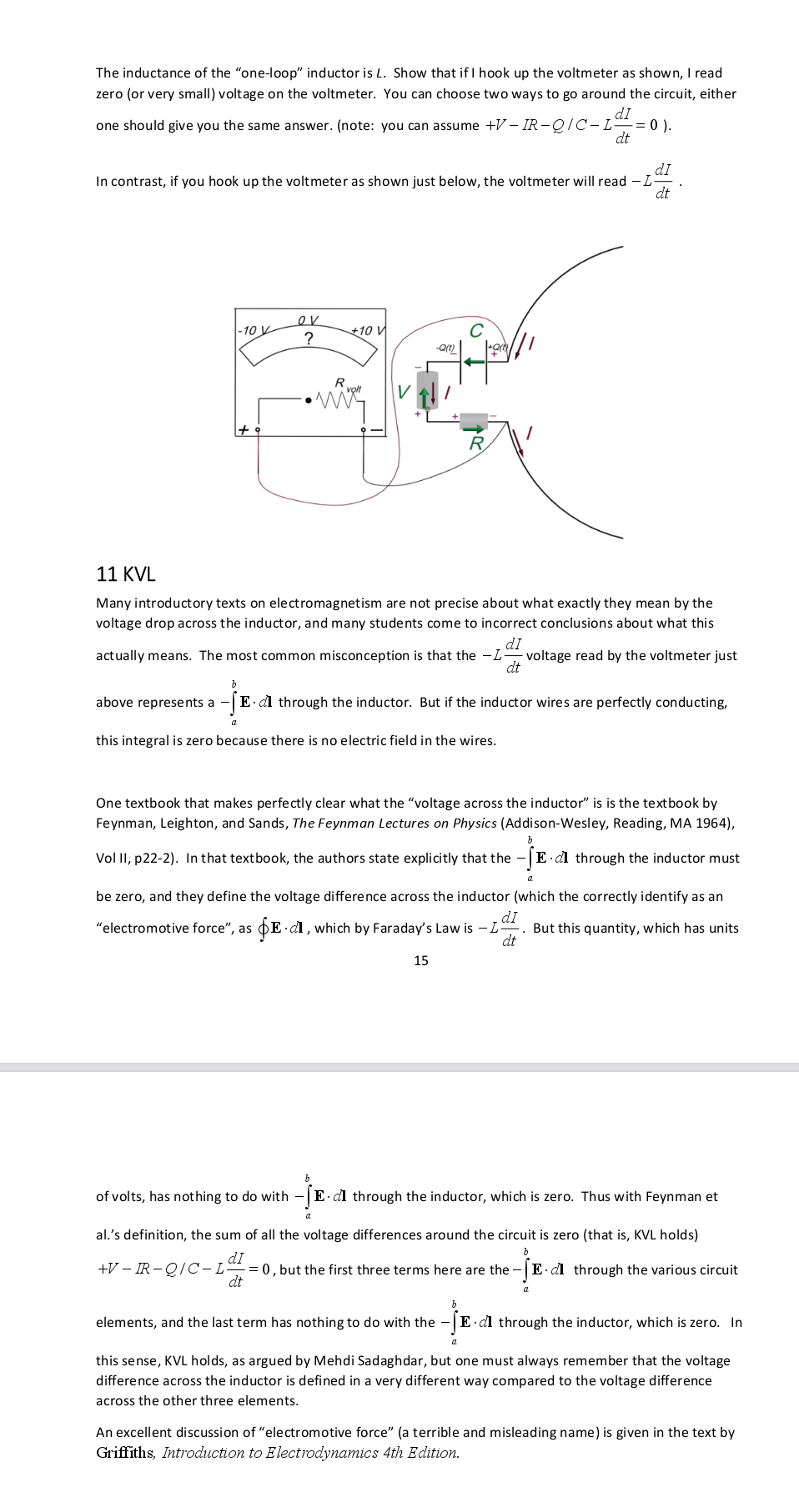
...
But you probably won't find many confutations in the comments section, because Duhamel, like fromjesse, delete the comments that tell them they are wrong and why. For example, in his last video "Voltage in a loop is weird", a post by Silicon Soup stating that by putting the probes inside the magnetic region a voltage was induced in the loop has disappeared.

Here's the reason:

https://i.postimg.cc/vZ6BM4Wn/screenshot-3.png
...
Just to set the record straight, your statement is false.
Neither I nor Duhamel delete comments just because they disagree with us.
I don't know whether Bob deleted any specific comments,

You literally contradicted yourself from one sentence to the other.
Sentence two says "Duhamel does not delete comments because..."
Sentence three says "I do not know whether Bob deleted any specific comments..."
Did you talk to Bob expressely about this? Sentence three says you didn't. Also says you seem fine about talking of what you do not know.


If you had quoted me in context, it would not falsely appear that I contradicted myself.

I have not talked to Bob about it, but your statement was a blanket statement that THERE WOULD BE SEEN NO CONFUTATIONS  in the comments on my channel or Bob's channel because you said (implicitly) we deleted all disagreeing comments.

Your statement was out right false, and observably false, because there are still dissenting comments on both his channel and mine.

Record straightened: I can recall at least three posts that disappeared from RSD A. videos. One is the comment from Silicon Soup, stating that by running the probes in the magnetic flux region he was intercepting flux and this inducing a voltage. It was deleted along with a timestamped comment by Copernico Felinis (or, by using your non-insulting name: felinus retardus). Another one is a comment of I believe Mick Vall (Or Mark Fruchtman, a name like that... M---- --a---) where he told Bob that he was wrong and he should not be teaching this wrong concepts because it would cause confusion in students (and he also explained why and where he was wrong). The whole thread disappeared, along with other comments discussing technicalities.

He may have removed some entire conversations, I don't know. But I do know that he didn't remove all disagreeing comments as you stated, and that is an observable fact.

So, keep your "false" to you.

If you had said that Bob had deleted SOME users, or SOME disagreeing comments, but left others, then I'd have had no problem with your claim.
If you had said that I had banned you but not others, then I'd have no problem.

And then there is that exchange with Mr. Anderson. It tells all you need to know.
I don't know what you're talking about.

Quote
but I don't recall deleting any specific comments, but what I did do is ban ONE particular person (felinus retardus) who was being insulting to my viewers as well as myself. I did not delete all of his comments,
But you did not publish some?
I don't remember not publishing any. Most of my videos have un-moderated comments, but sometimes youtube flags them and I have to go in and approve them.
If you left a comment after I banned you, then it may not have been published and it probably didn't even show up in my unpublished comments.

I guess that, regarding the insults, you meant comments like this one  - in that case I can understand


Source: your channel - image here https://i.postimg.cc/N081Kppk/screenshot-fromjesse-insults.png

Oh, my bad. That was Samuel Snerden cold open post and he was talking about Lewin. Did you ban him as well, for insulting your viewers? But of course not. Lewin is certainly not a viewer of yours.

Lewin has never left any comment. If he wants to come comment under my videos then he can complain about Samuel Snerden's comments.

Also about insults, and then I'll drop it definitively: I have been through the exchange you are having with ThinkFat. In just two or three comments you manage to call bsfeechannell: "clueless", "totally idiotic", "either he's fulla BS or he's not being honest", "your hero the ignorant bsfeechannel", "he's either ignorant or disingeneous".

Again, if you quoted me in context, you'd see why. The chap literally responded thus:

bsfeechannel responded to "A resistor under the influence of the external varying magnetic field also behaves as non-ideal voltage source" by saying  "But, but, but, but fromjesse said that the copper rings generate voltages, while the resistors drop it! How can I properly learn Ohms law, KVL, good probing and oscilloscope operation if you guys keep contradicting each other? Aw, unbelievable!"

Doesn't he know that resistors, capacitors, and inductors all have resistance, inductance, and capacitance? (excepting superconductors which have no resistance)

Apart from that thing about pots and kettles, I don't think your ban was motivated by insults. You seem pretty comfortable with insults in your channel. I believe it's something else. I wonder what that could be.  :-//

Well, you're the ONLY one I've banned on that topic. I banned a few pharmacy spammers but that's something else.
You can look and there are LOTS AND LOTS of comments of all the regulars like Trevor and Melo and I don't remember who else. They argued hard and long -- but didn't resort to insulting me, and I never banned them. You're the only one I banned.

Maybe when you are cornered, you get insecure?
Nope, look at all the other guys who were much more meticulous and thorough - they would be the ones that cornered me and caused insecurity. But you can see that the discussions go on for a LONG time, and they are still there, and those users are not banned.

Quote
Let's try to figure out the issue.

Will you start insulting people in here, as well?
If not, I can try to explain what is wrong with what you believe.
Namely:

1. That sentence of Belcher is about the RLC lumped circuit of section 10. Read pages 15 and 16. It's not about the unlumpable Lewin ring.


That's where I was quoting from. Wouldn't you say that he clearly describes that there are two different attributes, both of which use the unit volt, but one of which is always zero across an inductor and one which is what a volt meter reads, which is how KVL holds as argued by Mehdi?

He says "Thus with Feynman et al.’s definition, the sum of all the voltage differences around the circuit is zero (that is, KVL holds) "


2. The note of McDonald (it's not a paper, it's a note for his students) has been through many revisions, so you should also specify the date it was last updated. The most recent I have on my laptop says November 14, 2018. And he uses a definition of "voltage drop" that 'others' (namely the IEC) call 'scalar potential difference'. Therefore he is talking about the component of the voltage that is solely determined by the conservative electric field generated by the distribution of charge displaced by Eind. It's just that, and he says so on page 10, after formula (35). The scalar PD alone is insufficient to describe the physical system. In fact, you cannot even apply Ohm's law to that 'voltage drop' as he calls it. And he acknowledges that voltmeters do not measure that 'voltage drop' of his, but the path integral of the total electric field Etot (as Belcher says, as well).
Therefore, when stores will sell AC voltmeters that can read that scalar potential difference, that definition of his will come very handy. Till then, a lot of people prefer to use actual voltage, the one that can be measured by voltmeters and that is path-dependent. It is also much easier to treat.

Yes, I have the same November 14th 2018.

And yes, Dr. McDonald cleary states:

"Lewin’s circuit is within the range of applicability of Kirchhoff’s loop equations, which can be used to predict measurements by the “voltmeters” in the experiment."

What gives? You say Lewin's circuit is not within the range of applicability of Kirchhoff's loop equations. McDonald says it is.
He literally says it. In writing.

3. By reading your thread with ThinkFat for the video "The Lewin loop inside an iron core - KVL still holds" it appears to me you have problems with basic electromagnetism.

Naturally, but then again, to me, it looks like you don't understand basic electromagnetism. That's why I'm here trying to learn.

You say con can "correctly lump" the circuit, but Lewin's ring is not lumpable.

Huh? I never said Lewin's ring was not lumpable.
McDonald said it is within the range of applicability of Kirchhoff's loop equations.

Are you saying it's not lumpable, but it's still within the range of applicability of Kirchhoff's loop equations?

You also seem to think that if your "volt meter leads do not cut through any changing magnetic fields [...], according to Faraday's law [...] there will be no voltage induced along my volt meter leads".
Do you really think that in order to induce a voltage, the conductors need to pass through the variable magnetic field region?

I think that a wire running axially along the magnetic "lines of force" will have no voltage induced in it,  and no force exerted on it. That's why voice-coil actuators have the winding running at right angles to both the axis of movement and the axis of magnetic "lines of force."

Is that the reason you want to drill a hole into the toroidal core?
LOL Didn't you see the laughing face emoticons after that statement?

The point of the hole would be to allow measuring a half-turn. Look at it like this, here's a cross section at the toroid with the hole shown as a pipe:
(d|b)  Parenthesis=primary winding, db=core material, and |=wire through the core.

The current in the "(" half of the winding will be flowing UP, and the current in the ")" half of the winding will be flowing DOWN, which means that the voltage induced along the length of "|" will be zero, thus allowing us to measure the voltage of a half of a turn hahahahahaha.

And by the way, since the core hogs the vast majority of the magnetic flux due to it's high permeability, the magnetic flux in the drilled hole would be pretty small, unless operating beyond the saturation point of the now narrowed cross section of the core.

You also seem anxious about looking inside a transformer.
It was a half-turn-on-a-toroid joke, man.
It's because people were trying to get me to do the EI-Core experiment on a toroid knowing that I couldn't do a fractional turn.

But that is the crux of the problem: Lewin's ring has placed two resistor inside the coil of a single turn transformer, creating a circuit that cannot be model with a lumped component.

Why can't it be modeled as several lumped components? Didn't Dr. McDonald say it could be?

Faraday's law is clear that:

Voltage generated = -N * ((delta(B*A)) / delta-t)

where N=Turns
B=Magnetic Flux
A=Area

Sooo, if we have a circular transformer winding composed of two copper windings of nearly of half a turn, and two resistors which take up almost no turn, why can't it be modeled as two half turns and two resistors?

If you want to get really into the details, sure the resistor might be 0.5% of a turn, so would be modeled as 0.5% of a turn plus its resistance.
And yes, the copper traces have some resistance, so you would model them as a winding plus a couple milliohms.
And of course both the resistor and the copper trace have some parasitic capacitance as well, so if you want to be really accurate you can model that as well.

But for the sake of discussion, the stray attributes are very small compared to the primary attributes or induced voltage and ohmic voltage drop.

N need not bee an integer.

Continuously variable variacs have been around forever - I've got one, real pretty, all silver plated, you turn the knob, and the wiper slides or rolls along the winding providing a movable  tap at any of an infinite number of positions, limited only by the smoothness of the winding wire and the wiper roller.
 

Offline bdunham7

  • Super Contributor
  • ***
  • Posts: 7902
  • Country: us
Re: #562 – Electroboom!
« Reply #249 on: November 16, 2021, 05:41:54 am »
Continuously variable variacs have been around forever - I've got one, real pretty, all silver plated, you turn the knob, and the wiper slides or rolls along the winding providing a movable  tap at any of an infinite number of positions, limited only by the smoothness of the winding wire and the wiper roller.

Could you show a picture or a link?  I've never seen a variac like that.   I assume you mean a line-voltage variac?
A 3.5 digit 4.5 digit 5 digit 5.5 digit 6.5 digit 7.5 digit DMM is good enough for most people.


Share me

Digg  Facebook  SlashDot  Delicious  Technorati  Twitter  Google  Yahoo
Smf