Author Topic: #562 – Electroboom!  (Read 111479 times)

0 Members and 3 Guests are viewing this topic.

Offline thinkfat

  • Supporter
  • ****
  • Posts: 2152
  • Country: de
  • This is just a hobby I spend too much time on.
    • Matthias' Hackerstübchen
Re: #562 – Electroboom!
« Reply #375 on: November 21, 2021, 04:45:06 pm »
Wow, interesting!  Every book I have checked say the induced EMF is lumpable (for example, check the attached figure from Electromagnetics for Engineers by Ulaby).
That's just dumb. The thing that is being "lumped" here is not the EMF, it's the electric potential that "builds up" along a path (of conductor) that is subjected to the EMF.
Everybody likes gadgets. Until they try to make them.
 

Offline jesuscf

  • Frequent Contributor
  • **
  • Posts: 503
  • Country: ca
Re: #562 – Electroboom!
« Reply #376 on: November 21, 2021, 04:55:33 pm »
Wow, interesting!  Every book I have checked say the induced EMF is lumpable (for example, check the attached figure from Electromagnetics for Engineers by Ulaby).
That's just dumb. The thing that is being "lumped" here is not the EMF, it's the electric potential that "builds up" along a path (of conductor) that is subjected to the EMF.

You are right.  Let us call it that VEMF(t) as the book does.
Homer: Kids, there's three ways to do things; the right way, the wrong way and the Max Power way!
Bart: Isn't that the wrong way?
Homer: Yeah, but faster!
 

Offline Sredni

  • Frequent Contributor
  • **
  • Posts: 746
  • Country: aq
Re: #562 – Electroboom!
« Reply #377 on: November 21, 2021, 05:52:47 pm »
Wow, interesting!  Every book I have checked say the induced EMF is lumpable (for example, check the attached figure from Electromagnetics for Engineers by Ulaby). 

You probably have checked fewer books than I have. Purcell does not say so. Ramo Whinnery and VanDuzer does not say so. Haus and Melcher does not say so. Brandao Faria does not say so...
Could it be that the books you checked were talking about lumped circuits?
Because that's what Hayt was doing - he was showing how to "amend KVL" to make it work with LUMPED inductors. (Edit: Components you access via their closed together terminals.)
And so does Ulaby. I have that book, as well, and in my edition that figure is in section 6.2 "Stationary loop in a time-varying magnetic field": it expressly references a lumped inductor which has terminals.

Quote from: Ulaby
"The transformer EMF is the voltage difference that would appear across the small opening between terminals 1 and 2, ..."

You know why the opening has to be small (and the terminals close together)? Because the circuit you put your component in has to be shrunk to a dimensionless point. Has to be lumped. Ulaby is talking about a lumpable circuit that is being lumped.

Quote
By the way, when you suggested the solution to the problem I posted, what is the first thing you do?  You lumped the EMF!

No, I applied Faraday. I can do that even with lumpable circuits, if I choose not to lump them. Here's one picture from one of my answers on EE Stack Exchange where I properly apply Faraday to a lumpable RLC circuit (the 5 + 3 + 0 = 8 approach)


and here is how I can turn Faraday into "amended KVL" for the same circuit system - which I now treat as lumped (the 5 + 3 - 8 = 0 approach) by using a circuit path that does not inclued the variable magnetic region


If the circuit is lumpABLE I can treat is either as lumpED (applying 'extended KVL') or as NON lumped (applying Faraday).
If the circuit is UNlumpABLE, I am stuck with Faraday.

It's that simple. Really.

Quote
At this point whom should we believe, the literature (and experiments) or Sredni?

You could believe Purcell, Ramo Whinnery Vanduzer, Haus and Melcher, Faria, Romer, Roche, Nicholson, ... basically any professor who explicitly treated the general case, and did not limit their discussion to lumped circuits alone.

« Last Edit: November 21, 2021, 06:40:45 pm by Sredni »
All instruments lie. Usually on the bench.
 

Offline jesuscf

  • Frequent Contributor
  • **
  • Posts: 503
  • Country: ca
Re: #562 – Electroboom!
« Reply #378 on: November 21, 2021, 08:06:04 pm »
Wow, interesting!  Every book I have checked say the induced EMF is lumpable (for example, check the attached figure from Electromagnetics for Engineers by Ulaby). 

You probably have checked fewer books than I have. Purcell does not say so. Ramo Whinnery and VanDuzer does not say so. Haus and Melcher does not say so. Brandao Faria does not say so...
Could it be that the books you checked were talking about lumped circuits?
Because that's what Hayt was doing - he was showing how to "amend KVL" to make it work with LUMPED inductors. (Edit: Components you access via their closed together terminals.)
And so does Ulaby. I have that book, as well, and in my edition that figure is in section 6.2 "Stationary loop in a time-varying magnetic field": it expressly references a lumped inductor which has terminals.

Quote from: Ulaby
"The transformer EMF is the voltage difference that would appear across the small opening between terminals 1 and 2, ..."

You know why the opening has to be small (and the terminals close together)? Because the circuit you put your component in has to be shrunk to a dimensionless point. Has to be lumped. Ulaby is talking about a lumpable circuit that is being lumped.

Quote
By the way, when you suggested the solution to the problem I posted, what is the first thing you do?  You lumped the EMF!

No, I applied Faraday. I can do that even with lumpable circuits, if I choose not to lump them. Here's one picture from one of my answers on EE Stack Exchange where I properly apply Faraday to a lumpable RLC circuit (the 5 + 3 + 0 = 8 approach)


and here is how I can turn Faraday into "amended KVL" for the same circuit system - which I now treat as lumped (the 5 + 3 - 8 = 0 approach) by using a circuit path that does not inclued the variable magnetic region


If the circuit is lumpABLE I can treat is either as lumpED (applying 'extended KVL') or as NON lumped (applying Faraday).
If the circuit is UNlumpABLE, I am stuck with Faraday.

It's that simple. Really.

Quote
At this point whom should we believe, the literature (and experiments) or Sredni?

You could believe Purcell, Ramo Whinnery Vanduzer, Haus and Melcher, Faria, Romer, Roche, Nicholson, ... basically any professor who explicitly treated the general case, and did not limit their discussion to lumped circuits alone.

Fantastic!  Now here is another problem for you.  The same 'Lewin' ring as before with a AA battery in series (as show in the attached figure).  Compute the voltages V1 and V2 at t=0.  Also, the battery, although slowly, is discharging over time, but at t=0 the voltage between the terminals of the battery 1.5V.
Homer: Kids, there's three ways to do things; the right way, the wrong way and the Max Power way!
Bart: Isn't that the wrong way?
Homer: Yeah, but faster!
 

Offline Jesse Gordon

  • Regular Contributor
  • *
  • Posts: 126
  • Country: us
Re: #562 – Electroboom!
« Reply #379 on: November 21, 2021, 08:41:58 pm »
voltage between nodes A and D (VAD) which are half a circle apart.[/b]

As I've stated, the definition of that voltage is the very issue that is not agreed upon.  So if you want a number for an answer, you have to specify your definition or method of measurement.  One definition that might be interesting is the voltage measured by a voltmeter whose leads go in an exact straight line between the points.  You would need a gap or hole in the inductor and core that are providing the magnetic flux, but that may be doable.

Or one could use the definition of voltage given by the International Electrotechnical Committe IEC 60050
https://www.electropedia.org/iev/iev.nsf/display?openform&ievref=121-11-27
and specify the path, as I did.

So let me ask you this. In the following diagram:

https://i.postimg.cc/pXFDpYwk/deleteme.jpg
In the above diagram, I show the test circuit.

In the below image:

https://i.postimg.cc/9QctKwkp/Screenshot-2021-11-21-at-12-23-35-IEC-60050-International-Electrotechnical-Vocabulary-Details-fo.png

In the above image, I show a screenshot of the IEC definition you reference.

NOW: Using your provided definition, and the circle path diagram above that, in your opinion or by your calculations, what will be the voltage between the points connected by the non-conductive green line, assuming a 1v/turn induced voltage for the whole loop?

Assume that the upper section encloses exactly half of the dB/dt, and that the wires are superconductors.
Also assume that the solenoid is infinitely long.

As I see it, you have yourself in a bit of a bind.

If you say "Can't be known" then you're obviously using the wrong definition for volts.

If you say zero, then transformers have zero volts output, which is obviously false.

If you say non-zero, then Lewin goofed by not accounting for the voltage induced in his probe leads between the "point of measurement" and the "volt meter."

So what's the voltage across the two wire ends shown by the green path?
 

Offline bsfeechannelTopic starter

  • Super Contributor
  • ***
  • Posts: 1667
  • Country: 00
Re: #562 – Electroboom!
« Reply #380 on: November 21, 2021, 08:55:18 pm »
Wow, interesting!  Every book I have checked say the induced EMF is lumpable

Nope. They don't say that. It's all in your head.

In that specific case, that EMF is "lumpable" because the geometry of the circuit allows it. The varying magnetic field is contained in a specific area of the circuit. What is omitted from that diagram is the path taken to calculate the EMF. The path doesn't encompass the area where the varying mag field is. Note also how the author says the loop is stationary.
« Last Edit: November 21, 2021, 09:32:50 pm by bsfeechannel »
 

Offline jesuscf

  • Frequent Contributor
  • **
  • Posts: 503
  • Country: ca
Re: #562 – Electroboom!
« Reply #381 on: November 21, 2021, 09:04:46 pm »
Wow, interesting!  Every book I have checked say the induced EMF is lumpable

Nope. They don't say that. It's all in your head.

In that specific case, that EMF is lumpable because the geometry of the circuit allows it. The varying magnetic field is contained in a specific area of the circuit. What is omitted from that diagram is the path taken to calculate the EMF. The path doesn't encompass the area where the varying mag field is. Note also how the author says the loop is stationary.

Sure, why not; show me: in the Lewin's circuit I posted above, solve for V1 and V2 without lumping the EMF.
Homer: Kids, there's three ways to do things; the right way, the wrong way and the Max Power way!
Bart: Isn't that the wrong way?
Homer: Yeah, but faster!
 

Offline thinkfat

  • Supporter
  • ****
  • Posts: 2152
  • Country: de
  • This is just a hobby I spend too much time on.
    • Matthias' Hackerstübchen
Re: #562 – Electroboom!
« Reply #382 on: November 21, 2021, 09:06:07 pm »
If you say "Can't be known" then you're obviously using the wrong definition for volts.

If you say zero, then transformers have zero volts output, which is obviously false.

If you say non-zero, then Lewin goofed by not accounting for the voltage induced in his probe leads between the "point of measurement" and the "volt meter."

So what's the voltage across the two wire ends shown by the green path?

I don't think the conclusions you draw from the possible answers are valid.
But I can also predict that you will not understand, and reject, the answer once given.  :-DD
« Last Edit: November 21, 2021, 09:09:29 pm by thinkfat »
Everybody likes gadgets. Until they try to make them.
 

Offline Sredni

  • Frequent Contributor
  • **
  • Posts: 746
  • Country: aq
Re: #562 – Electroboom!
« Reply #383 on: November 21, 2021, 09:55:28 pm »
No, I applied Faraday. I can do that even with lumpable circuits, if I choose not to lump them. Here's one picture from one of my answers on EE Stack Exchange where I properly apply Faraday to a lumpable RLC circuit (the 5 + 3 + 0 = 8 approach)


Fantastic!  Now here is another problem for you.  The same 'Lewin' ring as before with a AA battery in series (as show in the attached figure).  Compute the voltages V1 and V2 at t=0.  Also, the battery, although slowly, is discharging over time, but at t=0 the voltage between the terminals of the battery 1.5V.

The solution is in the image you quoted. It's fascinating that you do not realize it.
Just switch the capacitor with a resistor, and there you will see how to apply Faraday to your circuit, and how the right hand side only features the induction EMF, while the battery EMF is accounted for as part of the circulation.
You really can't see it, if you think putting a battery in Lewin's ring can represent some sort of difficulty.

Anyway, I solved step by step (again for the general case, I am not interested in exercises) and I tried to spell out every single step - including sign conventions and the many parts you can break the circulation path integral (something you can read, certainly better explained in Ramo Whinnery and VanDuzer - but you won't read it, right?), and how the direction of the current depends on who wins between the induction EMF and the battery.

But before scanning these two pages, I want that some KVLer do the measurements I propose.
(Post to come tomorrow)
« Last Edit: November 21, 2021, 09:58:37 pm by Sredni »
All instruments lie. Usually on the bench.
 

Offline Sredni

  • Frequent Contributor
  • **
  • Posts: 746
  • Country: aq
Re: #562 – Electroboom!
« Reply #384 on: November 21, 2021, 10:02:30 pm »
If you say "Can't be known" then you're obviously using the wrong definition for volts.

If you say zero, then transformers have zero volts output, which is obviously false.

If you say non-zero, then Lewin goofed by not accounting for the voltage induced in his probe leads between the "point of measurement" and the "volt meter."

So what's the voltage across the two wire ends shown by the green path?

I don't think the conclusions you draw from the possible answers are valid.
But I can also predict that you will not understand, and reject, the answer once given.  :-DD

So, you too have a crystal ball!
All instruments lie. Usually on the bench.
 

Offline jesuscf

  • Frequent Contributor
  • **
  • Posts: 503
  • Country: ca
Re: #562 – Electroboom!
« Reply #385 on: November 21, 2021, 10:11:10 pm »
No, I applied Faraday. I can do that even with lumpable circuits, if I choose not to lump them. Here's one picture from one of my answers on EE Stack Exchange where I properly apply Faraday to a lumpable RLC circuit (the 5 + 3 + 0 = 8 approach)


Fantastic!  Now here is another problem for you.  The same 'Lewin' ring as before with a AA battery in series (as show in the attached figure).  Compute the voltages V1 and V2 at t=0.  Also, the battery, although slowly, is discharging over time, but at t=0 the voltage between the terminals of the battery 1.5V.

The solution is in the image you quoted. It's fascinating that you do not realize it.
Just switch the capacitor with a resistor, and there you will see how to apply Faraday to your circuit, and how the right hand side only features the induction EMF, while the battery EMF is accounted for as part of the circulation.
You really can't see it, if you think putting a battery in Lewin's ring can represent some sort of difficulty.

Anyway, I solved step by step (again for the general case, I am not interested in exercises) and I tried to spell out every single step - including sign conventions and the many parts you can break the circulation path integral (something you can read, certainly better explained in Ramo Whinnery and VanDuzer - but you won't read it, right?), and how the direction of the current depends on who wins between the induction EMF and the battery.

But before scanning these two pages, I want that some KVLer do the measurements I propose.
(Post to come tomorrow)

What you are telling me by making an equivalence from my circuit to your circuit is that you lumped the induced EMF and them you used KVL to solve it!  Great to know!!!
Homer: Kids, there's three ways to do things; the right way, the wrong way and the Max Power way!
Bart: Isn't that the wrong way?
Homer: Yeah, but faster!
 

Offline Sredni

  • Frequent Contributor
  • **
  • Posts: 746
  • Country: aq
Re: #562 – Electroboom!
« Reply #386 on: November 21, 2021, 10:12:05 pm »
So let me ask you this. In the following diagram:

Assume that the upper section encloses exactly half of the dB/dt, and that the wires are superconductors.
Also assume that the solenoid is infinitely long.
So what's the voltage across the two wire ends shown by the green path?

Let's see if you can forecast my answer by looking at this image


https://i.postimg.cc/15n8XGXJ/Voltage-can-be-path-dependent.jpg

Some hints:
What color would I use for that kind of path?
What color would I use for the probes in Lewin's setup?
All instruments lie. Usually on the bench.
 

Offline Sredni

  • Frequent Contributor
  • **
  • Posts: 746
  • Country: aq
Re: #562 – Electroboom!
« Reply #387 on: November 21, 2021, 10:21:28 pm »
What you are telling me by making an equivalence from my circuit to your circuit is that you lumped the induced EMF and them you used KVL to solve it!

You really can't see it, can you?
You're like that guy in Kevin Smith's "Mallrats" movie. The guy who spend hours in front of the stereoscopic poster and everybody else can tell what the image is, while he can't see it.

All instruments lie. Usually on the bench.
 

Offline bsfeechannelTopic starter

  • Super Contributor
  • ***
  • Posts: 1667
  • Country: 00
Re: #562 – Electroboom!
« Reply #388 on: November 21, 2021, 10:49:42 pm »
McDonald: ... He uses diversion and an obsolete version of a "law" to create an apparent paradox.

That is the root of the controversy.  Everything else is noise.

Lewin thinks that this is the definition of KVL:

\$\oint_{}^{}E.dL=0\$


Aaaaaand Lewin is right. KVL holds for every circuit for which \$\oint_{}^{}E.dL=0\$. If you calculate \$\oint_{}^{}E.dL\$ and it results in zero, you can apply KVL blind-folded. You can even bet your life on it.

So it is ironic that in Lewin's world, KVL always holds. ALWAYS. The only thing you need to do is to find a path for which  \$\oint_{}^{}E.dL=0\$ and you're good to go.

Quote
While this is the accepted definition of KVL (since at least 1909, the earliest reference I found, but must likely older than that):

\$emf=\oint_{}^{}E.dL=-\frac{d }{dt}\int_{S}^{}B.dS\$

Uhh, nope. According to McDonald, this is the more accepted definition of KVL:

0 = ∑loop voltage drops = ∑iIiRr + ∑j( ̇Ij Lj + ∑k ̇IkMjk) + ∑l Ql/Cl −∑mEm  (1)

And he remarks:
Lewin has also supplemented his lectures with two notes [34, 35], where is it claimed that Kirchhoff’s (2nd)
circuit law is that ∮loop E·dl= 0 for any circuit loop, rather than the more standard version, eq. (1), for
(coupled) R-L-C circuits.


Bold letters are mine.

So, it holds with the following caveats:

Caveat #1 Your circuit must be made exclusively of lumped components (R, L, C). I.e. it must be lumpable.
Caveat #2 Some unlumpable circuits can be solved by the equation (1), however the EMF can in no way be measured.
Caveat #3 It doesn't hold for whatever circuits where you have radiation.
Caveat #4 It doesn't hold for whatever circuits where its size is comparable to the wavelength.
Caveat #5 It doesn't take into consideration the self inductance of the rest of the circuit.
Caveat #6 While Lewin's version is absolutely precise. This version is an approximation.
Caveat #7 Mehdi says, however, that this "version" of KVL always holds. Which is not true.
Caveat #8 Mehdi is stupid.
Caveat #9 Stupidity is a moral issue. Not and intellectual one.

So, in Mehdi's world KVL doesn't always hold. The reason why it doesn't requires a little study, but Mehdi wants to convey the idea that you can be an instant expert in electromagnetism without the proper education. Welcome to the 21st century. I'm loving it.
 

Offline bsfeechannelTopic starter

  • Super Contributor
  • ***
  • Posts: 1667
  • Country: 00
Re: #562 – Electroboom!
« Reply #389 on: November 21, 2021, 11:15:10 pm »
I'm not saying that there are electric fields INSIDE a conductor, stationary or otherwise, that we know because the -∫E.dl=0 for a superconductor.
I am talking about the EMF across the ends of a wire according to -L(dI/dt), which Belcher clearly describes as being non-zero in a changing magnetic field even for a superconductor.

Precisely. If you "walk" between the ends through the conductor, you will find zero volts. If you "walk" between the same ends, but now chosing the gap between the ends as your path, you'll find your non-zero voltage. These two voltages are different, although they refer to the same two points.

End of story. Have a good night's sleep.

Quote
That should be the second thing you learned in your electromagnetism course out there.

The sole purpose of an engineering degree is to able to debunk KVLers.

Quote
Are you thinking there's a difference between a stationary wire in a dB/dt field, and a moving wire in a stationary and non-uniform B field?

Before you set out to give answers on Youtube, learn to ask the proper questions.
« Last Edit: November 21, 2021, 11:20:24 pm by bsfeechannel »
 

Offline jesuscf

  • Frequent Contributor
  • **
  • Posts: 503
  • Country: ca
Re: #562 – Electroboom!
« Reply #390 on: November 21, 2021, 11:17:49 pm »
What you are telling me by making an equivalence from my circuit to your circuit is that you lumped the induced EMF and them you used KVL to solve it!

You really can't see it, can you?
You're like that guy in Kevin Smith's "Mallrats" movie. The guy who spend hours in front of the stereoscopic poster and everybody else can tell what the image is, while he can't see it.


And in the diagram you put there is the electric field in the circuit conservative or non-conservative?  Because it looks to me that you are applying KVL despite having a non-conservative electric field in the circuit, which is correct.
« Last Edit: November 22, 2021, 12:41:26 am by jesuscf »
Homer: Kids, there's three ways to do things; the right way, the wrong way and the Max Power way!
Bart: Isn't that the wrong way?
Homer: Yeah, but faster!
 

Offline jesuscf

  • Frequent Contributor
  • **
  • Posts: 503
  • Country: ca
Re: #562 – Electroboom!
« Reply #391 on: November 21, 2021, 11:21:23 pm »
McDonald: ... He uses diversion and an obsolete version of a "law" to create an apparent paradox.

That is the root of the controversy.  Everything else is noise.

Lewin thinks that this is the definition of KVL:

\$\oint_{}^{}E.dL=0\$


Aaaaaand Lewin is right. KVL holds for every circuit for which \$\oint_{}^{}E.dL=0\$. If you calculate \$\oint_{}^{}E.dL\$ and it results in zero, you can apply KVL blind-folded. You can even bet your life on it.

So it is ironic that in Lewin's world, KVL always holds. ALWAYS. The only thing you need to do is to find a path for which  \$\oint_{}^{}E.dL=0\$ and you're good to go.

Quote
While this is the accepted definition of KVL (since at least 1909, the earliest reference I found, but must likely older than that):

\$emf=\oint_{}^{}E.dL=-\frac{d }{dt}\int_{S}^{}B.dS\$

Uhh, nope. According to McDonald, this is the more accepted definition of KVL:

0 = ∑loop voltage drops = ∑iIiRr + ∑j( ̇Ij Lj + ∑k ̇IkMjk) + ∑l Ql/Cl −∑mEm  (1)

And he remarks:
Lewin has also supplemented his lectures with two notes [34, 35], where is it claimed that Kirchhoff’s (2nd)
circuit law is that ∮loop E·dl= 0 for any circuit loop, rather than the more standard version, eq. (1), for
(coupled) R-L-C circuits.


Bold letters are mine.

So, it holds with the following caveats:

Caveat #1 Your circuit must be made exclusively of lumped components (R, L, C). I.e. it must be lumpable.
Caveat #2 Some unlumpable circuits can be solved by the equation (1), however the EMF can in no way be measured.
Caveat #3 It doesn't hold for whatever circuits where you have radiation.
Caveat #4 It doesn't hold for whatever circuits where its size is comparable to the wavelength.
Caveat #5 It doesn't take into consideration the self inductance of the rest of the circuit.
Caveat #6 While Lewin's version is absolutely precise. This version is an approximation.
Caveat #7 Mehdi says, however, that this "version" of KVL always holds. Which is not true.
Caveat #8 Mehdi is stupid.
Caveat #9 Stupidity is a moral issue. Not and intellectual one.

So, in Mehdi's world KVL doesn't always hold. The reason why it doesn't requires a little study, but Mehdi wants to convey the idea that you can be an instant expert in electromagnetism without the proper education. Welcome to the 21st century. I'm loving it.

Excellent!  So according to what you say above KVL, holds for any EMF that is not induced by a varying magnetic field?  If for some reason you have a EMF induced by a magnetic field in series with another source of EMF, what do you do then?  Add then together?  Isn't it that KVL?
Homer: Kids, there's three ways to do things; the right way, the wrong way and the Max Power way!
Bart: Isn't that the wrong way?
Homer: Yeah, but faster!
 

Offline jesuscf

  • Frequent Contributor
  • **
  • Posts: 503
  • Country: ca
Re: #562 – Electroboom!
« Reply #392 on: November 22, 2021, 12:29:32 am »
Here is the solution of the problem I posted yesterday.

The given time varying magnetic flux density is:

\$B(t) = 0.7958 \cdot e^{\frac{{ - t}}{{0.1s}}} _{} T\$

The magnetic flux flowing through the ring is:

\$
\begin{array}{l}
 \Phi  = \int\limits_S {B(t) \cdot dS = } \int\limits_S {0.7958 \cdot e^{\frac{{ - t}}{{0.1s}}} _{} T}  \\
 \Phi  = 0.7958 \cdot e^{\frac{{ - t}}{{0.1s}}} _{} T \cdot \pi  \cdot (0.2)^2 m^2  \\
 \Phi  = 0.1 \cdot e^{\frac{{ - t}}{{0.1s}}} Wb \\
 \end{array}
\$

The corresponding EMF is:

\$
EMF =  - \frac{{d\Phi }}{{dt}} =  - \frac{{d(0.1 \cdot e^{\frac{{ - t}}{{0.1s}}} Wb)}}{{dt}} = \frac{{ - 0.1}}{{ - 0.1s}}e^{\frac{{ - t}}{{0.1s}}} Wb = e^{\frac{{ - t}}{{0.1s}}} V
\$

At t=0 the EMF is then:

\$
EMF = e^{\frac{{ - 0}}{{0.1s}}} V = 1V
\$

Use KVL to find the current, which is flowing clockwise:

\$
I = \frac{{EMF}}{{R_1  + R_2 }} = \frac{{1V}}{{100\Omega  + 900\Omega }} = 1mA
\$

Therefore:

\$
\begin{array}{l}
 V_2  = R_2  \cdot I = 900\Omega  \cdot 1mA = 0.9V \\
 V_1  =  - R_1  \cdot I =  - 100\Omega  \cdot 1mA =  - 0.1V \\
 \end{array}
\$

As for VAD we need to find an equivalent circuit and solve using KVL.  Since one quarter loop connects the '+' terminal of each resistor to node 'A', we can represent that quarter loop as voltage source with one quarter of the total voltage of 0.25V.  The same goes for the '-' terminal of both resistors.  By the way, this is the step that Lewin solved incorrectly!


We can find now VAD using KVL on one (or both, it is the same value) of the branches:

\$
 \begin{array}{l}
 V_{AD}  = 0.25V - 0.1V + 0.25V = 0.4V \\
 V_{AD}  =  -0.25 + 0.9V - 0.25V =  0.4V \\
 \end{array}
\$

EDIT: corrected calculation of VAD and added image of equivalent circuit.


« Last Edit: November 30, 2021, 02:26:01 am by jesuscf »
Homer: Kids, there's three ways to do things; the right way, the wrong way and the Max Power way!
Bart: Isn't that the wrong way?
Homer: Yeah, but faster!
 

Offline Jesse Gordon

  • Regular Contributor
  • *
  • Posts: 126
  • Country: us
Re: #562 – Electroboom!
« Reply #393 on: November 22, 2021, 03:33:04 am »
If you say "Can't be known" then you're obviously using the wrong definition for volts.

If you say zero, then transformers have zero volts output, which is obviously false.

If you say non-zero, then Lewin goofed by not accounting for the voltage induced in his probe leads between the "point of measurement" and the "volt meter."

So what's the voltage across the two wire ends shown by the green path?

I don't think the conclusions you draw from the possible answers are valid.
But I can also predict that you will not understand, and reject, the answer once given.  :-DD

So, you too have a crystal ball!


That answers a lot! It's the three gypsy  Fortune Tellers with their Crystal Balls!

I thought this felt like a three ring circus, and now I know why!

(Lewin rings, of course.)

 :-DD :-DD :-DD :-DD :-DD :-DD
 

Offline Jesse Gordon

  • Regular Contributor
  • *
  • Posts: 126
  • Country: us
Re: #562 – Electroboom!
« Reply #394 on: November 22, 2021, 04:01:01 am »
I'm not saying that there are electric fields INSIDE a conductor, stationary or otherwise, that we know because the -∫E.dl=0 for a superconductor.
I am talking about the EMF across the ends of a wire according to -L(dI/dt), which Belcher clearly describes as being non-zero in a changing magnetic field even for a superconductor.

Precisely. If you "walk" between the ends through the conductor, you will find zero volts. If you "walk" between the same ends, but now chosing the gap between the ends as your path, you'll find your non-zero voltage. These two voltages are different, although they refer to the same two points.

End of story. Have a good night's sleep.

Quote
That should be the second thing you learned in your electromagnetism course out there.

The sole purpose of an engineering degree is to able to debunk KVLers.

Too bad you didn't get an engineering degree, you might have been able to debunk KVLers if you had!   :-DD

Quote
Are you thinking there's a difference between a stationary wire in a dB/dt field, and a moving wire in a stationary and non-uniform B field?

Before you set out to give answers on Youtube, learn to ask the proper questions.

It's awesome how refuse to answer questions because you know it'd betray your lack of learning.

I know the right questions to ask, but you won't answer them.

Let me try again:

Does KVL hold for a loop consisting of resistors and closed-magnetic-circuit-core transformer secondary windings?

For example, would V1 and V2 in the following diagram work as lumped elements in a loop with some resistors, and would KVL hold?


https://i.postimg.cc/fTgyDNp0/20211119-030105.jpg

Specifically, would KVL hold in the following circuit?

https://i.postimg.cc/15gbsCmz/20211119-232948.jpg

Would V1, V2, & V3 sum to zero?

Why are you guys so cagey about admitting that KVL at least APPEARS to hold in this scenario?

I say APPEARS because you won't admit that it DOES hold, so I'm trying to meet you half way, and I'm asking you only to agree to the undeniably obvious fact that at the very least KVL appears to hold as measured with a volt meter.

Once you can come to grips with the plainly observable part of reality then we can discuss why you think it's not ACTUALLY holding even though it gives every appearance of holding.

But if you deny observable reality, why should anybody trust you about the more complex subjective claims you make?

And by the way, it's not ME giving answers on yourtube, it is OBSERVABLE REALITY. I use real test equipment, real transformers, real wires, and real ETC., to show REALITY. That's just what reality is.
« Last Edit: November 22, 2021, 04:06:51 am by Jesse Gordon »
 

Offline Jesse Gordon

  • Regular Contributor
  • *
  • Posts: 126
  • Country: us
Re: #562 – Electroboom!
« Reply #395 on: November 22, 2021, 04:51:20 am »
So let me ask you this. In the following diagram:

Assume that the upper section encloses exactly half of the dB/dt, and that the wires are superconductors.
Also assume that the solenoid is infinitely long.
So what's the voltage across the two wire ends shown by the green path?

Let's see if you can forecast my answer by looking at this image


https://i.postimg.cc/15n8XGXJ/Voltage-can-be-path-dependent.jpg

Some hints:
What color would I use for that kind of path?
What color would I use for the probes in Lewin's setup?

Goodness you dodge and weave when asked questions.

But look at the diagram you provided. From that any reasonable person would conclude that the paths which do not collide with the core material, (i.e. either completely inside or completely outside) are lumped. Only the ones that have an unknown position part way into the dB/dt area should be unlumpable according to your upper diagram.

And yet you show all those paths that are outside and all the paths that are inside as unplumpable. Why aren't they lumpable? They are consistent, unambiguous, and by George they work with KVL as measured with a volt meter.


 Tell me more about your crystal ball. Did you get it in gypsy class?
 

Offline Sredni

  • Frequent Contributor
  • **
  • Posts: 746
  • Country: aq
Re: #562 – Electroboom!
« Reply #396 on: November 22, 2021, 05:26:09 am »

Goodness you dodge and weave when asked questions.

But look at the diagram you provided. From that any reasonable person would conclude that the paths which do not collide with the core material, (i.e. either completely inside or completely outside) are lumped.


You know, I don't think you know the meaning of lumped. You try to apply it to paths? What is a lumpable path? I apply it to circuits (you need to lump them, squeeze them to make them as small as a point, dimensionless) or components (same). And why can't you lump a circuit or a component that has a magnetic flux region inside? Because flux needs an area to have a meaning. You can't squeeze it into a point without losing meaning. That's the point (pun intended). But if the component has terminals close together...

But what is a 'lumped path'? Where did you heard of this?
A lumpABLE system can be considered lumpED or UNlumped depending on what you consider its circuit path. If the circuit path contains the magnetic flux region, you cannot squeeze it beyond the perimeter of that region. If the component contain the flux region, you take the terminals out, put them very close together so that they can occupy (so to speak) the space of a point on your circuit and attach them to a gap as wide as a point (so to speak) on your circuit path. Your circuit path, including the connection to the component, is now shrinkable to a point.

What the heck is a 'lumpable path'?

Here is the answer to your previous quiz
You talk about measuring reality, so this is my prediction for your circuit. If you don't like the polarities flip the signs.


https://i.postimg.cc/Yq1ZDcPY/KVL-works-if-I-leave-out-the-magnetic-region.jpg

Note that you won't be able to measure any voltage in the perfectly conducting wire of the ring, in accordance with Ohm's law. So, are you a lumper, or today you decide that there is voltage in the wires and in the probes? I have to ask.

Now, it's my turn.

Same circuit (you can even use a single resistor if you want. My prediction is that you will observe zero volts in the wires even when the sliders (you sliding the probe tips along the ring) get in contact inside the core.
So how does KVL "appear" to hold?


https://i.postimg.cc/CKfjJ0PV/KVL-dies-if-the-magnetic-region-is-inside-my-circuit-path.jpg

Now, if today you are still a lumper, please tell me where is the EMF on the ring.
« Last Edit: November 22, 2021, 05:31:24 am by Sredni »
All instruments lie. Usually on the bench.
 

Offline Sredni

  • Frequent Contributor
  • **
  • Posts: 746
  • Country: aq
Re: #562 – Electroboom!
« Reply #397 on: November 22, 2021, 05:39:14 am »

\$
\begin{array}{l}
 V_2  = R_2  \cdot I = 900\Omega  \cdot 1mA = 0.9V \\
 V_1  =  - R_1  \cdot I =  - 100\Omega  \cdot 1mA =  - 0.1V \\
 \end{array}
\$

As for VAD: any two nodes that are half a circle apart have half of the total EMF.  In this case |VAD|=0.5V.

I see you used Ohm's law to compute the voltage drop along the resistors. So Ohm's law works. Wonderful.
Can you apply Ohm's law to compute the voltage drop across the wire that goes from R1 to point A?
Because we know that from A to D we have a voltage of half a volt, while across R1 we have what 0.1 V (fix the signs as you please while I put popcorns in the microwave). So, what gives?

(you can use the resistivity of copper, or a very low resistance for the wires, for example 1 milliohm, if zero resistance is a problem)
All instruments lie. Usually on the bench.
 

Offline Jesse Gordon

  • Regular Contributor
  • *
  • Posts: 126
  • Country: us
Re: #562 – Electroboom!
« Reply #398 on: November 22, 2021, 05:48:26 am »
Yiiieee! Here comes another KVL'er! Get your crystal balls started, Gentlemen!

The 3 gypsies, the last bastion of truth.
 

Offline Jesse Gordon

  • Regular Contributor
  • *
  • Posts: 126
  • Country: us
Re: #562 – Electroboom!
« Reply #399 on: November 22, 2021, 08:17:51 am »

Goodness you dodge and weave when asked questions.

But look at the diagram you provided. From that any reasonable person would conclude that the paths which do not collide with the core material, (i.e. either completely inside or completely outside) are lumped.


You know, I don't think you know the meaning of lumped. You try to apply it to paths? What is a lumpable path? I apply it to circuits (you need to lump them, squeeze them to make them as small as a point, dimensionless) or components (same). And why can't you lump a circuit or a component that has a magnetic flux region inside? Because flux needs an area to have a meaning. You can't squeeze it into a point without losing meaning. That's the point (pun intended). But if the component has terminals close together...

But what is a 'lumped path'? Where did you heard of this?

Again, you're quoting me out of context. My comment was in reply to your diagram where you showed different hypothetical paths within an element:

https://i.postimg.cc/VvFWycbH/Voltage-can-be-path-dependent.jpg
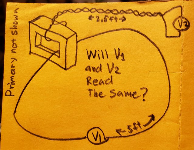
You clearly show different possible paths within the element, the 5v and 0v paths inside that element are unambiguous,  unvarying, and if that is the path in that element, then it can be considered a lumped element in a KVL loop and KVL will hold.

You already admitted that there is no practical difference between V1 and V2 configurations in this diagram:

https://i.postimg.cc/fTgyDNp0/20211119-030105.jpg
You also admitted that V2  in the above diagram would work as a lumped element in a KVL loop.

So if V1 and V2 are functionally identical, and V2 holds in a KVL loop, then why not V1? They have the same voltage. They are functionally identical. What's the difference?


A lumpABLE system can be considered lumpED or UNlumped depending on what you consider its circuit path. If the circuit path contains the magnetic flux region, you cannot squeeze it beyond the perimeter of that region. If the component contain the flux region, you take the terminals out, put them very close together so that they can occupy (so to speak) the space of a point on your circuit and attach them to a gap as wide as a point (so to speak) on your circuit path. Your circuit path, including the connection to the component, is now shrinkable to a point.

If configuration V2 and configuration V1 in my above yellow diagram are functionally identical, then why does it matter?

ARE YOU SAYING THAT THE TERMINALS MUST COME VERY CLOSE TOGETHER OR MY VOLT READINGS WILL BE DIFFERENT?

You already admitted that the V1 and V2 readings in my above yellow diagram would be identical, so why does it matter if the wires coming out of the transformer have to come near eachother? Does that change the voltage? Does it change whether my volt meter readings will all add up to zero around the loop of which that transformer secondary is an element?

What the heck is a 'lumpable path'?

As stated above. You quoted me out of the context of the diagram I was replying to.

Here is the answer to your previous quiz
You talk about measuring reality, so this is my prediction for your circuit. If you don't like the polarities flip the signs.


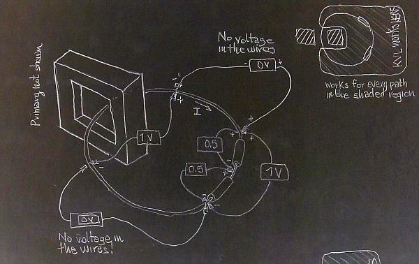
https://i.postimg.cc/R04QGyHs/KVL-works-if-I-leave-out-the-magnetic-region.jpg

I see you noticed that you made the same mistake Lewin did and you got one of the volt meters backwards, but at least you caught it in time to put a text note that says I can flip the volt sign.
So yes, I'd like to flip the sign on the left-hand meter which reads 1V. You have to keep the meters all pointing clockwise or counter clockwise -- but all the same way for a given test -- around the loop. That's just the way KVL is. If you mix up your volt meter signs even with pure batteries and resistors, KVL will appear to fail then too.

With all the volt meters pointing plus-clockwise, then you can see that the voltage sums to zero, just like KVL says.

So do we agree that  KVL at least APPEARS to hold on your above diagram, since taken in a positive clockwise series of element voltage difference readings, all the voltage differences sum up to zero?

Note that you won't be able to measure any voltage in the perfectly conducting wire of the ring, in accordance with Ohm's law. So, are you a lumper, or today you decide that there is voltage in the wires and in the probes? I have to ask.

I don't understand the question. I think you're making a dichotomy between a lumper and there being voltage IN the wires.. but I'm not sure what you're trying to ask. If a wire has induced voltage, I'd rather say that it has induced voltage across it.

I don't know what you mean by "lumper" - I say I'm just an observer of reality.  I did not decide anything today.

Try your question again more clearly please.

But maybe this answers you. Like I said a hundred times already, my argument is that in your diagram above (and the others functionally the same), the wire passing through the transformer core MODELS AND MEASURES as if the voltage is induced at the point the wire passes through the inner most area INSIDE the core, and the wires outside the core MODEL AND MEASURE as if they there is no voltage induced across them.

Once you realize these self evidence facts, then I'd love to go on to talk about what you think is really going on.

But getting you to admit to the obvious and undeniable reality of how things model and measure has been like pulling teeth from a whale.

So do we agree then that in a setup as you show in your diagram above, the transformer secondary winding MODELS AND MEASURES as if the entire induced voltage is where the wire passes through the core, and that the wires outside the core MODEL AND MEASURE as if there is no voltage induced in them?

Now, it's my turn.

Same circuit (you can even use a single resistor if you want. My prediction is that you will observe zero volts in the wires even when the sliders (you sliding the probe tips along the ring) get in contact inside the core.
So how does KVL "appear" to hold?


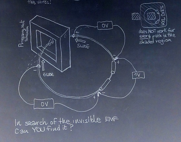
https://i.postimg.cc/cH5RxJ52/KVL-dies-if-the-magnetic-region-is-inside-my-circuit-path.jpg

Now, if today you are still a lumper, please tell me where is the EMF on the ring.

KVL continues to hold once you MODEL REALITY.

The REALITY is that by sliding your volt meter probe through the core, you now have ANOTHER SECONDARY WINDING, AND ANOTHER LOOP!

Like this:


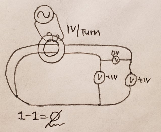
https://i.postimg.cc/LX6wZVFJ/20211121-235058.jpg

See? You have TWO secondary windings, with the SAME number of turns, and the SAME direction, and they are both having induced across them the SAME VOLTAGE and in the SAME POLARITY at the SAME TIME.

Of course the difference between them will be zero, because 1-1=0. Go figure.

And you don't just have one loop anymore, you have TWO loops. Or three, depending on how you want to model and measure.

If you MODEL REALITY, like I've been saying the whole time, KVL will hold with elements composed of the secondary windings on closed-magnetic-circuit-core transformers.

If you DON"T model reality, then all of physics will fail you, not just KVL with transformers, but KVL without transformers, MaxEQ, Ohms law, EVERYTHING.

I don't know what you mean by "lumper" but the EMF MODELS AND MEASURES as being across the transformer secondary at the very point it crosses through the core on a closed-magnetic-circuit-core transformer.

By the way, if you put two AA batteries minus to minus and measure the  voltage difference between the positive terminals, the difference will also be zero. You could use this same "trick" and add in an undocumented battery into your loop and make KVL fail with just batteries and resistors too, as I'm sure you saw hahahaha   :-DD https://youtu.be/V_Gs8tSqBRY  :-DD

The point is that by adding in additional voltage sources/drops and creating nested loops but pretending there is only one loop will get you in the same trouble with pure batteries and resistors as with a transformer.

So do we agree that if we run two identical parallel windings on a transformer that the voltage difference between them is zero?


Share me

Digg  Facebook  SlashDot  Delicious  Technorati  Twitter  Google  Yahoo
Smf