-
JFET as replacement for analog switch like DG444 and question about RDS(on)flat
Posted by julian1 on 14 Mar, 2017 20:30 -
I am interested in using an analog switch to switch various shunt resistors, for current measurement ranges.
An analog switch like the DG444 has a typical RDS(on) resistance of around 50ohms.
However, it also has a variation of around 9ohms over the range of +VE to -VE, which will influence current measurement when used in series with a precision resistor and limit choice to higher-valued sense resistors. And 9 ohms may well be a best case, for Maxim https://datasheets.maximintegrated.com/en/ds/DG444-DG445.pdf. Neither Vishay or Intersil quote the parameter.
There are other analog switches with lower RDS(on) that also have flatter responses - eg. DG1411, but they are less common, have higher leakage currents (1-2nA versus 80pA), and come in more difficult to use packages (tssop versus soic).
As an alternative I am wondering if a JFET might be used as a bidirectional analog switch?. Something like a J111 http://www.mouser.com/ds/2/149/J111-889320.pdf
The J111 specs suggest 30ohm with 0V VGS, and leakage is only 1nA when VGS is -10V. I have no experience with JFETs but understand they can be used bidirectionally. My question is - how RDS(on) of the JFET would be characterized if the D or S was varied over a range of say +10V to -10V?
-
To have a JFET turned on, one usually sets the gate - source voltage to zero, so one often needs a kind of sensing amplifier. After that, there will be essentially no variation of the on resistance with the DC voltage of drain and source. It is more in the off mode, that the negative gate voltage is changing and thus the leakage can depend on the voltages.
With the CMOS switched much of the R_on variations happen more close to the supply rails. At the typical low voltage used at shunts this is much smaller. One might even be able to use MOSFETs, if voltages are below about 200 mV or with two back to back MOSFETs in series.
However there still is a variation of the on resistance with temperature. So usually one designs the a current sensing circuit to have separate paths / switched for current and voltage sensing. So even if the switch resistance is changing it would not make a big difference.
Dave has in interesting video one current sensing on his new DMM on how to switch shunts and still get a low burden voltage. -
Quote
To have a JFET turned on, one usually sets the gate - source voltage to zero, so one often needs a kind of sensing amplifier. After that, there will be essentially no variation of the on resistance with the DC voltage of drain and source.
This is totally misunderstood. A JFET is a voltage controlled current source, and with the gate voltage set to 0 it will act as a current regulator, which in an ideal case would have infinite "on resistance".
-
Quote
To have a JFET turned on, one usually sets the gate - source voltage to zero, so one often needs a kind of sensing amplifier. After that, there will be essentially no variation of the on resistance with the DC voltage of drain and source.
This is totally misunderstood. A JFET is a voltage controlled current source, and with the gate voltage set to 0 it will act as a current regulator, which in an ideal case would have infinite "on resistance".
In the low drain to source voltage (e.g. less than 100 mV) range a JFET acts like a resistor controlled by the gate voltage. It is only at higher voltages the the current can not increase further and thus the JFET will act as a current limiter. -
Use an optomosfet with AC output support. Some exist with on impedance less than 0.06 ohm and are good to +/-6 amps.
(This is 3 orders of magnitude compared to any of your solutions, this will give you the best accuracy unless you go to power mosfets with a bunch of gate driving support voltages and circuitry.)
Check this part number > CPC1907B
You wont find this kind of isolation from your control supply voltage with discrete components with ZERO leakage current.
The down side to the part I listed is that when off, it will leak 1ua. But you can always use a weaker optomosfet with a higher on resistance, but, a lower leakage current.
-
To clarify a couple of points. This is for higher valued current sense resistors eg. > 1k.
For lower valued shunts (higher-current) two back-to-back series n-channel mosfets or relays would be desirable for their current handling ability.
I am interested in bidirectional current sense - eg. a positive or negative drop across the shunt and switch with reference to GND, and with a +-10V D to S sense range. -
We're talking switching in different shunt resistors for current measurement, right?
You can eliminate the errors complete by using two switches per resistor.
On switch for connecting the relevant shunt resistor to the input socket, and one switch connecting the shunt resistor to your sense amplifier.
The first switch is outside the measuring loop (like a test-lead resistance).
The second will (hopefully) look into a high impedance amplifier, so on-resistance is negligible. -
These are a little pricey as switches, but they go to 2.5 ohms when on:
https://www.maximintegrated.com/en/products/analog/analog-switches-multiplexers/MAX4669.html
Run the 2 in parallel for 1.25ohm on, however, you wont get the blind supply isolation/impedance at any A to B impedance of the optomosfets who's gates are optically driven.
-
We're talking switching in different shunt resistors for current measurement, right?
You can eliminate the errors complete by using two switches per resistor.
On switch for connecting the relevant shunt resistor to the input socket, and one switch connecting the shunt resistor to your sense amplifier.
Yes, I have considered that and am still considering it. The trade-off is extra circuit complexity and I am aware of schematics for range switching that do it with one switch - using different strategies depending on the specific range and leakage control needed.
But, in a similar vein - I wonder about connecting two analog switches- in series on just one side of the shunt. I think analog swiches like the dg444 use a p-channel and n-channel in parallel, which is what gives their non flat response when swept between +VE and -VE. But it might be possible to arrange two of them in series to cancel some of this effect. -
Quote
But, in a similar vein - I wonder about connecting two analog switches- in series on just one side of the shunt. I think analog swiches like the dg444 use a p-channel and n-channel in parallel, which is what gives their non flat response when swept between +VE and -VE. But it might be possible to arrange two of them in series to cancel some of this effect.
So that's not extra complexity?
My suggestion is a sure-fire way to solve this, but you'd rather speculate on things that are not in the datasheet?
-
For current shunts one can avoid to include drop on the switches in the measured voltage. One does not even need a second switch, just measure the voltage through the higher shunts. For very low currents (e.g. < 10 µA) one could consider a trans-impedance amplifier instead of a simple shunt.
For shunt use the voltage level seen by the shunt is usually rather constant and often in the middle. So this is more like the sweet spot of R_on vs V_DC curve. Using a N and P MOSFET in parallel is already made to compensate voltage dependence, but near the supply rails just one of them is active and thus the not so good performance.
Besides voltage dependence there is also temperature dependence, so one should avoid having the switch resistance in the critical path, except if it is really small.
Can you show us an approximate schematics on what is planed ? -
Quote
One does not even need a second switch, just measure the voltage through the higher shunts.
Do you mean series connecting the shunts and then tapping into the shunt column from the input side?
Trying to visualize it, it's a nice idea. I like it. So you'd have the highest current shunt to ground, the next highest on top of that, and the third on top of that again?
And with a high impedance amplifier connected to the top of the shunt column, you can measure from there directly, and the switch impedances are completely eliminated?
Very nice, good idea. It should work.
-
The shunts in series is the standard circuit in multi-meters. The switches are for current steering only.
If works well up to about 100K for the highest shunt (thus about 2 µA current range) - for a much higher resistor the noise from that resistor adds significant to the noise.
The other point to take care of is leakage of MOSFET switches - so it might be worth using a relay for the very high currents. A < 1 µA range is tricky with the leakage current of a 50 A MOSFET in the circuit. -
Quote
Can you show us an approximate schematics on what is planed ?
Something like this,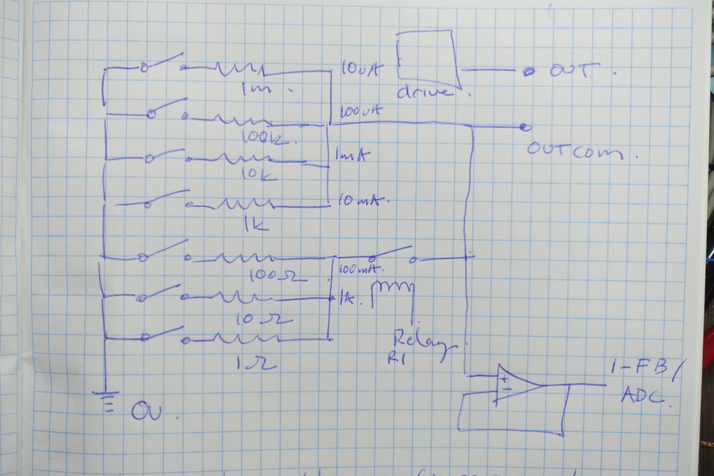
I like the idea of having the switches in series with the resistors for simplicity - we get a single-ended output voltage referenced to AGND.
The disadvantage is that the circuits are sensitive to any non-linearity in the switch over the voltage range.
But - almost all the voltage drop is across the resistors and not the switch. So we're really only concerned with very small voltage differences - as you already noted.
Additionally, having all the switches with one side tied to gnd means we get a common S (eg for Jfets) which makes it easy to drive G with respect to GND and not some floating/changing value.
I am considering dual n-mosfets with sources tied, or relays for lower value resistors (eg. 1-100ohm).
higher value resistors I am considering jfets or analog switches.
The additional bank relay r1 is to isolate high-leakage devices like mosfets - where leakage is on the order of 1uA.
Jfets and common analog switches have leakage on the order of 1nA.
Some analog switches are available with much lower leakage - eg. pA range - and they may be useful for higher valued resistors (eg > 1M) although their RDS(on) is > 1k.
I am considering using an addition bank-like relay on the higher valued resistor bank. A limitation of signal relays that I've found - such as the Omron GS6 is a minimum current of 10uA - so that would preclude their use for shunts over 1M.
-
Q: You do require voltage support below the GND, correct?
Q: What supply voltages are available to you?
-
Quote
Q: You do require voltage support below the GND, correct?
Yes. And I'm unsure of the implications of that for Jfets. I *think* that for symmetrical jfets (like j111) they should conduct current equally since S and D can be swapped. But when reverse biased (so to speak) VGS will be slightly less than the 0V on or -10V off VG to GND, because D is now tied to GND rather than S and there is some small additional voltage drop across the device. If that difference is linear it shouldn't matter.QuoteQ: What supply voltages are available to you?
not constrained. -
These are a little pricey as switches, but they go to 2.5 ohms when on:
https://www.maximintegrated.com/en/products/analog/analog-switches-multiplexers/MAX4669.html
Run the 2 in parallel for 1.25ohm on, however, you wont get the blind supply isolation/impedance at any A to B impedance of the optomosfets who's gates are optically driven.
I would recommend my last recommended switch with a +/- 20v supply. Your on resistance will be 1 ohm per switch and the off leakage current will be 0.01na at room temp.
-
One can still get a voltage referenced to a common GND with the shunts in series connection. Especially for the low ranges (R < 100 Ohms), the switch directly in series is not practical - It would at least need a second switch to also switch the voltage sensing path. For the low resistors there is usually little downside on having the shunts in series. It only gets a problem if the second lowest one is a shunt with 4 wire connections.
Usually the On resistance of FETs has a temperature coefficient in the 7000 ppm/K range - so the switch resistance needs to be much smaller part of the shunt resistance.
Another point to look at is overload protection. This is usually something like 2 or 3 diodes in series to limit the voltage at the shunts. This could be a problem for the very low ranges.
Even if the switches are not directly towards GND, the voltage at the shunts is usually small (e.g. < 200 mV) and thus does not make a big difference for JFET / MOSFET working as a switch. However gate leakage could be a problem with a +200 mV gate voltage to a JFET, so gate drive might need to be adjusted.
For the symmetrical JFETs D and S are really exchangeable - so calling them drain and source is at will. When off it does not matter if the gate voltage is at -10 V or -15 V. If on, the DS voltage is very small.
For shunts one usually does not need +-20 V rated switches. Something like the +-5 V or +-10 V rated ones are usually good enough. Very low on resistance switches usually also have more leakage. -
These are a little pricey as switches, but they go to 2.5 ohms when on:
https://www.maximintegrated.com/en/products/analog/analog-switches-multiplexers/MAX4669.html
Run the 2 in parallel for 1.25ohm on, however, you wont get the blind supply isolation/impedance at any A to B impedance of the optomosfets who's gates are optically driven.
I would recommend my last recommended switch with a +/- 20v supply. Your on resistance will be 1 ohm per switch and the off leakage current will be 0.01na at room temp.
Thanks. I agree, that is a superior part for maximizing the range between on resistance and off leakage. Also soic and with a pinout that would support low pcb leakage if that became a factor to optimize. I am not price sensitive. It looks like they might be getting the good switching spec by trading off band-width - which is perfectly fine for constant DC application. -
Quote
However gate leakage could be a problem with a +200 mV gate voltage to a JFET, so gate drive might need to be adjusted.
Good point, I need to think about this. -
This is the basic "serial shunt" Kleinstein suggested as a quick sketch from me. It's a very clean design and completely eliminates switch resistance in the measurement.
It will work with bipolar signals.
You'll need an opamp with high input impedance, but hey, those are thirteen a dozen nowadays.
And you can refine it with protection circuitry, relays for higher currents etc. This is just the principle.
-
Do you need to make one or two units incorporating this, or do you want to use it in a manufactured product made at higher volumes? I am guessing you'll use high accuracy, high precision resistors, and having a mux or a FET in series will defeat the point of that a little / add significant cost of human time for calibration.
-
This is the basic "serial shunt" Kleinstein suggested as a quick sketch from me. It's a very clean design and completely eliminates switch resistance in the measurement.
Thanks for the sketch, I wasn't quite understanding the in-series topology and I agree it's very elegant.
There might be a practicality given that IN (and therefore S) would be moving over the entire sense-range making gate control more difficult for active devices. But this would not be an issue for relays. -
Due to the normally small (e.g. less than 300 mV) voltage at shunts the variable voltage at the shunts is not a big problem - not even when using JFETs as switches. Over-current protection usually limits the voltage to something like 1-1.5 V.
The main advantage of a relay it that they have low leakage even for high current versions. Still the contact resistance can be a problem when in series with a low ohms shunt, but it does not matter if only in the current path.
The on resistance of FET switches is also temperature dependent with a rather high TC on the order of 7000 ppm/K. So one should really avoid having a FET as part of the shunt. As leakage goes up for low on resistance switches going very low in R_on is also limited. -
This is the basic "serial shunt" Kleinstein suggested as a quick sketch from me. It's a very clean design and completely eliminates switch resistance in the measurement.
Thanks for the sketch, I wasn't quite understanding the in-series topology and I agree it's very elegant.
There might be a practicality given that IN (and therefore S) would be moving over the entire sense-range making gate control more difficult for active devices. But this would not be an issue for relays.
That's no problem at all. If you check out the Siliconix/Vishay switches, they almost all have a +/- 15 V analog range and TTL compatible control inputs.