-
If you want to compare hydraulics to a boost smps, look at hydraulic ram pump.
You mean this ?
It is a great example of the mechanism (a) uses to move against the direction of applied force F1.
It is energy storage in this case compressed air and the equivalent of stick slip hysteresis generated by the one way valves.
At least this moves slow enough for people to see what happens while for the vehicle in case (a) you usually need a slow motion video to see the effect of energy storage and stick slip hysteresis.
-
Are animated diagrams now proof of something?
Oh, it's your animated diagram. Big difference, eh. -
What I was trying to say is that no device can move against the direction of applied force unless it uses energy storage and stick slip hysteresis.
And the trike vehicle I made of Lego moves against the direction of applied force, without any energy storage, and no slip stick hysteresis either; the one-directional torque transfer of the worm gear ensures that.
Not only I say that but it is clearly visible in the slow motion video I made.
You do realize that your single example device proves nothing except that that specific geometry cannot achieve it?
And that because my example device does achieve it, it disproves your assertion that it isn't possible?
Wait, I've asked you that before, and you sidestepped the questions then, too; just asserted something irrelevant as if that was an answer.
If one does a full mechanical analysis of my trike vehicle, they immediately see that the gearbox, the torque transfer, is what makes it possible to translate and redirect a linear force into another direction. In sailing vehicles, the mast acts like that gearbox. The direction change only requires something to push against, typically a static force (one that does no work). In sailing vehicles, that is provided by the keel, so that while it slices through the fluid smoothly and with very little friction in one direction, it provides a massive static force when one tries to push it sideways. In the trike, it is the contact friction between the driving wheels and the ground, the one preventing the wheels from slipping sideways and the vehicle rotating –– just like in a sailing vehicle.
I am immensely annoyed that you keep ignoring the trike vehicle, even though I explicitly provided you with a LeoCAD model (LeoCAD being free and available for Windows, Linux, and Mac OS), so that not only can you investigate exactly its components, you can replicate the vehicle and reproduce the results for yourself. (I used parts from Lego Technics set 9395 from 2012 that I got as a gift from a friend –– it reminded me from the set 8846 that was my first complex Lego set I had as a kid ––, and I opened the untouched set just to build this example trike.)
I could simplify the design so that Lego Technics set 42133 and at least two axle hubs (part 55982, available from Lego pick-and-build, and from Bricklink (55982) etc.) would suffice; or the very cheap Lego Technics set 30655 (released Jan 2023, ~ 5 USD) with at least two axle hubs (like part 93593), so the cost to build a copy of the vehicle would be less than $10 USD.
(I know your response is "I don't need to build that vehicle because my own example vehicle proves it is impossible for any other vehicle to work", which is a logical fallacy, but might convince feeble minds. Which is exactly why this is so infuriating: I'd love to help you understand, but no argument, logic, model, or explanation seems to change anything in your thinking.)
-
Are animated diagrams now proof of something?
Oh, it's your animated diagram. Big difference, eh.
? I needed to search (on google) what a RAM pump is so I included the animation for others to understand what it is if they never heard of it.
It is not just a kinematic animation it takes into account the forces involved so that it reflects how it works in real life.
I can make a correct animation for the vehicle (a) as well but it is seen very clearly in my video so even better than an animation. -
What I was trying to say is that no device can move against the direction of applied force unless it uses energy storage and stick slip hysteresis.
And the trike vehicle I made of Lego moves against the direction of applied force, without any energy storage, and no slip stick hysteresis either; the one-directional torque transfer of the worm gear ensures that.
Not only I say that but it is clearly visible in the slow motion video I made.
You do realize that your single example device proves nothing except that that specific geometry cannot achieve it?
And that because my example device does achieve it, it disproves your assertion that it isn't possible?
Wait, I've asked you that before, and you sidestepped the questions then, too; just asserted something irrelevant as if that was an answer.
If one does a full mechanical analysis of my trike vehicle, they immediately see that the gearbox, the torque transfer, is what makes it possible to translate and redirect a linear force into another direction. In sailing vehicles, the mast acts like that gearbox. The direction change only requires something to push against, typically a static force (one that does no work). In sailing vehicles, that is provided by the keel, so that while it slices through the fluid smoothly and with very little friction in one direction, it provides a massive static force when one tries to push it sideways. In the trike, it is the contact friction between the driving wheels and the ground, the one preventing the wheels from slipping sideways and the vehicle rotating –– just like in a sailing vehicle.
I am immensely annoyed that you keep ignoring the trike vehicle, even though I explicitly provided you with a LeoCAD model (LeoCAD being free and available for Windows, Linux, and Mac OS), so that not only can you investigate exactly its components, you can replicate the vehicle and reproduce the results for yourself.
I could simplify the design so that Lego Technics set 42133 and at least two axle hubs (part 55982, available from Lego pick-and-build, and from Bricklink (55982) etc.) would suffice; or the very cheap Lego Technics set 30655 (released Jan 2023, ~ 5 USD) with at least two axle hubs (like part 93593), so the cost to build a copy of the vehicle would be less than $10 USD.
(I know your response is "I don't need to build that vehicle because my own example vehicle proves it is impossible for any other vehicle to work", which is a logical fallacy, but might convince feeble minds. Which is exactly why this is so infuriating: I'd love to help you understand, but no argument, logic, model, or explanation seems to change anything in your thinking.)
Where is the video of your trike working ?
Your trike is more complex than the belt driven device I demonstrate.
There is also a problem if the wire you use as input is of center even slightly as then you can take advantage of the offset to create a lateral force against which to get leverage.
Hope you understand what I mean by wire being off center and you can imagine an exaggerate large spool where the wire is even outside the vehicle frame then you will have a huge lateral force as the third point against which you can leverage.
So because I need to explain the differences introduced by your model I prefer not to discuss your trike.
Try your trike with a lower gear ratio and see how the small off center offset of the string will try to rotate your vehicle. -
Your trike is more complex than the belt driven device I demonstrate.
Can you stop the constant diversions?
How about you tell us exactly what kind of example vehicle and its behaviour would convince you.
If you want, I can buy and build the exact belt driven model, using a Lego link chain as the belt, since Lego sprockets mesh nicely with it. Would this convince you your understanding is incorrect, or would you find something that would let you ignore that also? -
Quote
It is not just a kinematic animation it takes into account the forces involved so that it reflects how it works in real life.
But someone elses animation that did the same was discounted in favour of your belief. You cannot have it both ways. No, you should not have it both ways - clearly, you are doing your best to achieve the former. -
Quote
Where is the video of your trike working ?
Your trike is more complex than the belt driven device I demonstrate.
Jeez! You don't need a video - he tells you how to build an actual model, and what with. You could make that by tomorrow if you cared enough. It's simpler than you telling other people to build the stuff you dream up, and you could see exactly for yourself how it works. But you can't let yourself do that because you know it will work and you wouldn't be able to handle it. -
...
The left wheel of your trolley is a different object to the right wheel, the stationary block and the treadmill belt are also different objects. So your F1 and F2 cannot be viewed as the mutual actions of two bodies upon each other, and are therefore not the subject of Newton's third law as defined above.
...
While you may consider the left wheel a different object from the right wheel in this particular example they are not.
The way let and right wheel are connected to each other makes them act as a single object.
This equivalent diagram to (a) may make it more visible to you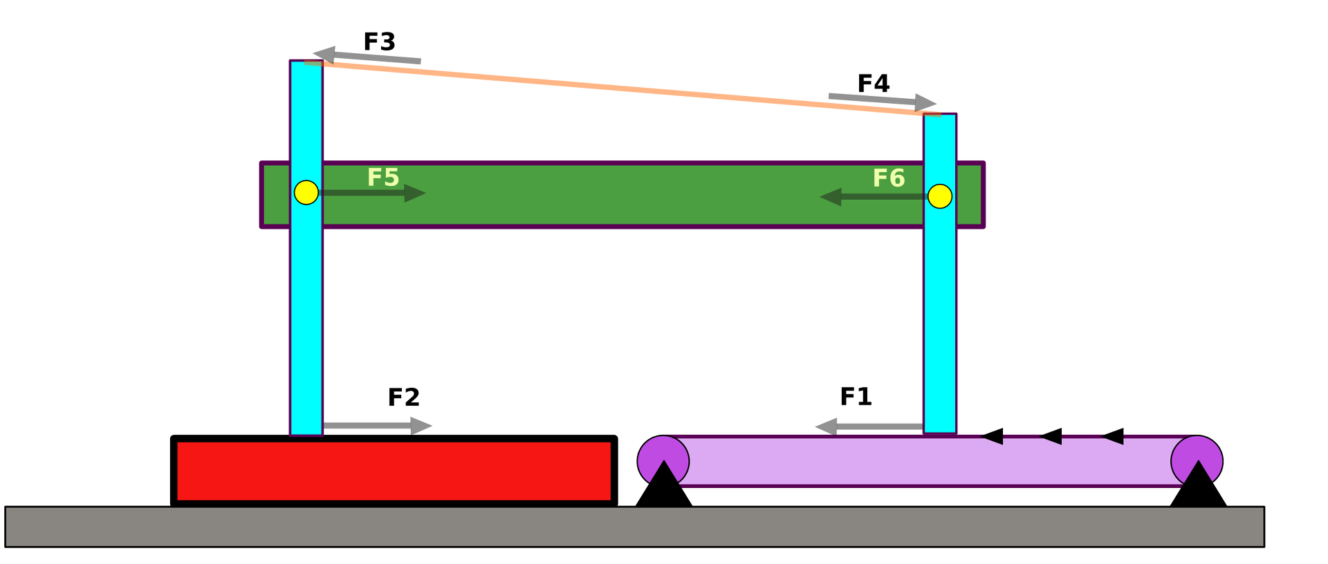
You can als imagine having this in your hands right hand applies F1 and the left hand will apply the equal and opposite force F2 else there will be no F1 so Newton's 3'rd law pair.
All this pairs in the above diagram are newton's 3'rd law pairs so F1 = F2, F3 = F4 and F5 = F6
A pantograph is a very similar mechanism to your articulated table shown above (4 struts and 4 hinge joints), and it too is only anchored at two points. And yet it works, it is not locked. Why does your version of Newton's third law make the articulated table behave as a rigid object, but not the pantograph? -
Your trike is more complex than the belt driven device I demonstrate.
Can you stop the constant diversions?
How about you tell us exactly what kind of example vehicle and its behaviour would convince you.
If you want, I can buy and build the exact belt driven model, using a Lego link chain as the belt, since Lego sprockets mesh nicely with it. Would this convince you your understanding is incorrect, or would you find something that would let you ignore that also?
Yes this similar belt or even chain driven vehicle will convince me. But are you assuming that I faked the videos ? -
Quote
It is not just a kinematic animation it takes into account the forces involved so that it reflects how it works in real life.
But someone elses animation that did the same was discounted in favour of your belief. You cannot have it both ways. No, you should not have it both ways - clearly, you are doing your best to achieve the former.
You can make an animation based on kinematics only (not representing what happens in reality) or you can make an animation including the effects of forces.
-
A pantograph is a very similar mechanism to your articulated table shown above (4 struts and 4 hinge joints), and it too is only anchored at two points. And yet it works, it is not locked. Why does your version of Newton's third law make the articulated table behave as a rigid object, but not the pantograph?
Please build this out of cardboard and test as likely you can not visualize what will happen. That Pantograph is very different in the way the connections are made and also the place where force is applied.
And I already shown that it can not move in this video https://odysee.com/@dacustemp:8/stick-slip-removed-from-front-wheels:0
Or are you accusing me of faking that video ? Or do you have an alternative explanation for that ?
First 15 seconds shows that mechanism is locked F2=F1
The last few seconds shows that allowing slip at input wheel results in movement against the direction of applied force using energy storage. -
A pantograph is a very similar mechanism to your articulated table shown above (4 struts and 4 hinge joints), and it too is only anchored at two points. And yet it works, it is not locked. Why does your version of Newton's third law make the articulated table behave as a rigid object, but not the pantograph?
Please build this out of cardboard and test as likely you can not visualize what will happen. That Pantograph is very different in the way the connections are made and also the place where force is applied.
And I already shown that it can not move in this video https://odysee.com/@dacustemp:8/stick-slip-removed-from-front-wheels:0
Or are you accusing me of faking that video ? Or do you have an alternative explanation for that ?
First 15 seconds shows that mechanism is locked F2=F1
The last few seconds shows that allowing slip at input wheel results in movement against the direction of applied force using energy storage.
I don't need to build a pantograph out of cardboard. I have a real one, I have used it, and it works just as shown on the Wikipedia page.
In a recent message you wrote thisQuote...
I see what your view was but this simple problem wrongly understood has huge implications in all fields of engineering and science.
I'm not a physicist and I'm not enjoying explaining this (not am I good at explaining) but I do not see anyone else offering to explain this and it looks like majority memorize "facts" instead of properly understanding.
...
You seem to have taken on the mission of teaching the world how to understand Newton's third law. Well teach me! Please answer my question. Why does your version of Newton's third law make the articulated table behave as a rigid object, but not the pantograph? -
I'm actually utterly surprised you say that! Okay, I'll start working on it. I need to buy at least one cheap set for the chain, and some work lights so I can take an acceptable video of it working using my Ye Olde Phone (Honor 8 from late 2016/early 2017), so give me a day or two to get it done.How about you tell us exactly what kind of example vehicle and its behaviour would convince you.
Yes this similar belt or even chain driven vehicle will convince me.
Is the LeoCAD model of it useful for reproduction purposes, or is the video and images of the vehicle sufficient?
Is it okay if I replace the driving wheels with sprockets on a rack, to maximize traction and avoid slipping? Or are rubbery wheels on whatever surface it is put on more convincing for you?But are you assuming that I faked the videos?
No, it's just that a vehicle that fails to show something is not proof that it is impossible. I am telling you your vehicle was poorly constructed, and really cannot prove anything one way or another. (And, remember that one example that fails, does not show that it is impossible; it only proves that that one example fails.)
Lego Technic are precision components. Even though they are toys, their manufacturing tolerances are extremely tight, on the order of 2 micrometers (0.002 millimeters, less than one ten thousandth of an inch): higher than most metal machine shops' capabilities. They are also quite rigid, capable of withstanding quite high bending forces. This is what makes them excellent for engineering and mechanism examples.
Lego downside is their light weight, which means that wheels typically lack traction and tend to slip. It can be worked around by adding weight (coins, anything metal, fishing lure weights). As the set I used for the trike had large plastic rubber tires, they were perfect for adding weight and increasing traction (larger contact area). -
I'm actually utterly surprised you say that! Okay, I'll start working on it.
Before you go to too much effort, please be aware that this video exists:
https://imgur.com/a/lTqAFg6
-
I have not asked you to build a pantograph but the mechanism in my diagram as that one will not move unless it slides as a solid piece.
I don't need to build a pantograph out of cardboard. I have a real one, I have used it, and it works just as shown on the Wikipedia page.You seem to have taken on the mission of teaching the world how to understand Newton's third law. Well teach me! Please answer my question. Why does your version of Newton's third law make the articulated table behave as a rigid object, but not the pantograph?
It depends on where the articulations are
Do you feel like this look the same ?
Remove one articulation so that pantograph looks like letter A then you will see that there is no longer andy independent movement same as there is no movement on the mechanism in discussion.
You think it will move because you imagine pushing on the green part (vehicle body) but that is not allowed as vehicle body is floating and nothing pushes against that the F5 = F6 so there is zero net force acting against the body.
There must be some brain difference that do not allow some people to imagine what happens when forces are applied on an object else I can not explain why it is not obvious that F1 = F2 and in order to move the mechanism needs to slide as shown in my video.
Even seeing the video with the locked mechanism being slide in the same direction as applied force is no proof for you so you either want to blame that on something else or you think I faked the video. -
It seems we are circling back to same questions.
I provided the proof that mechanism is locked so F2 = F1 at constant speed and it moves in the same direction as applied force
first 15 seconds in this video https://odysee.com/@dacustemp:8/stick-slip-removed-from-front-wheels:0
Also showed what happens if input wheel (right wheel) is allowed to slip
https://odysee.com/@dacustemp:8/wheel-cart-energy-storage-slow:8
Unless you think I faked any of this videos no other proof is needed for my claim. And if you think it is faked it is on you to show the same setup working differently and that will disprove my theory unless you fake the video
Also your claim that vehicle should work because of gear ratio that allows F2 to be multiple times of F1 requires 3 points of contact and there are only two.
If you think force multiplication can be done with only two points of contact then you need to provide a link to a commercially available torque multiplier wrench that works with just two contact points and that will be proof enough for me. -
...
Do you feel like this look the same ?
No, one is an animation and the other is a static image, but to me that is not convincing proof that one is a rigid structure and the other isn't. But other than that, yes they look very similar, both are hinged quadrilaterals with extended edges.QuoteRemove one articulation so that pantograph looks like letter A then you will see that there is no longer andy independent movement same as there is no movement on the mechanism in discussion.
You think it will move because you imagine pushing on the green part (vehicle body) but that is not allowed as vehicle body is floating and nothing pushes against that the F5 = F6 so there is zero net force acting against the body.
Both the pantograph and the articulated table are made up of 4 struts in the form of a quadrilateral with extended edges and with the with hinge joints where they intersect. Such shapes do not form a rigid structure.
If I remove one strut from either of them, then they both form triangles with extended edges, with hinge joints where they intersect. Such triangles do indeed form a rigid structure. But I don’t see how that differentiates the two cases.
The pantograph and the articulated table are both only supported at two points. In both cases the mechanism in-between is floating. So I still don’t understand what the key difference is that makes one of them behave as a rigid structure, and not the other.QuoteThere must be some brain difference that do not allow some people to imagine what happens when forces are applied on an object else I can not explain why it is not obvious that F1 = F2 and in order to move the mechanism needs to slide as shown in my video.
You claim that it is obvious and say that you can imagine it, but you can't actually explain it in plain language. I'm afraid that plain language and mathematics is the only thing that I understand. Plain language and mathematics explanations served me well at university when I was studying for my physics degree. They served me when I was studying classical mechanics, special relativity, thermodynamics, statistical mechanics, electromagnetism, optics, solid state physics, quantum mechanics, electronics, etc. But somehow plain language and mathematics is not sufficient to explain Newton's third law to me, which for the last 50 years I thought that I understood.
Can you tell me, what is it about Newton's third law that makes it so very hard to understand?
-
You claim that it is obvious and say that you can imagine it, but you can't actually explain it in plain language. I'm afraid that plain language and mathematics is the only thing that I understand. Plain language and mathematics explanations served me well at university when I was studying for my physics degree. They served me when I was studying classical mechanics, special relativity, thermodynamics, statistical mechanics, electromagnetism, optics, solid state physics, quantum mechanics, electronics, etc. But somehow plain language and mathematics is not sufficient to explain Newton's third law to me, which for the last 50 years I thought that I understood.
Can you tell me, what is it about Newton's third law that makes it so very hard to understand?
I did better than just explain in plain language. I showed you a video of the real device being locked and dragged in the direction of applied force.
While the mechanism can move it will not move when F1 is applied as shown in the diagram. If force was applied to some other parts of that mechanism then movement is possible but that is not relevant for the current problem where mechanisms is locked and demonstrated in a real experiment.
If you connect the vehicle body to ground then you will have the F1 applied between the vehicle body and input wheel and for a 2:1 gear ratio you will have F2 between the output wheel and vehicle body equal with 2 * F1 so what you will consider a functional gearbox.
But as soon as you remove the vehicle body from ground the body is now floating and there is no net force acting on it.
I do not think Newton's 3'rd law is hard to understand but it seems I'm proven wrong by all your comments.
In school manuals for Newton's 3'rd law you will see an example like the one below.
So my question is simple. Just add this device or any other device you want instead of the Force meter thus just two points of contact one on the string connecting the human say human pulls with F1 and the other point connecting the string that is connected to wall say that force will be F2
Can any device be able to take the input F1 and have the output F2 be different than F1 ?
Maybe pulling instead of pushing makes it more easy to understand and it is a typical example for Newton's 3'rd law.
Unless that magic box replacing the Force meter has a third point for leverage it will not be able to have F2 different from F1.
-
I did better than just explain in plain language. I showed you a video of the real device being locked and dragged in the direction of applied force.
That video is a demonstration of something, but it is not an explanation of anything. Do you understand the difference between a demonstration and an explanation? -
That video is a demonstration of something, but it is not an explanation of anything. Do you understand the difference between a demonstration and an explanation?
I do that is the reason I'm here.
The video/video's is not an explanation is a proof that my explanation is correct.
It shows the vehicle in case (a) being dragged. That means a large F1 force is applied so large that it can drag the vehicle in the direction F1 is pointing and there is no wheel rotation so basically it acts as a solid object.
Relation between F1 and F2 is that F2 = F1 except for the short duration when vehicle is accelerate from zero to a constant speed when F1 = F2 + (m*a)
I will love you try and find an alternative explanation that is consistent with what is observed in that video first 15 seconds with the last few seconds showing that vehicle is not faked and that wheels can rotate if the input wheels (the ones on the right) are allowed to slip.
Then there is the slow motion video that shows what happens when the front wheel is allowed to slip but in slow motion. And that again is explained fully including the energy storage and the trigher provided by the hysteresis between stick and slip.
The force needed to overcome static friction is larger than the force needed after wheels starts to slip
Fs - force needed to overcome static friction.
Fk - force needed to overcome kinetic friction.
This are the triggers allowing small and fast charge discharge cycles and why the mechanism looks smooth without slow motion video even tho there are many fast cycles of charge discharge and the only way any vehicle of this type can drive against the applied force.
-
I've now also replicated the belt-driven mechanism, using Lego chains, as I happened to finally find where I stored my old Lego sets. I just need to simplify the model first.
Even electrodacus' own vehicle would work, if they just used a proper gear ratio. Their gearing is way too close to one (1:1). (That corresponds to \$\lambda = r/R\$, i.e. as shown in my math in my reply #97, when the movement is impossible. Simply put, electrodacus' picked exactly the worst possible gear ratio for their demonstration vehicle.)
As shown in the video linked to most recently by IanB, the driven wheel must turn multiple times for each turn of the driving wheel, and the wheels rotating in the same direction. (For soft rubbery tires, a ratio of 1:2 to 1:5 works well.)
The closer the ratio is to 1:1, the better traction you need. If you use a very small ratio, say 1:20 to 1:40 (i.e. for one turn of the driving wheels, the driven/belt wheel turns 20 to 40 times for wheels of same size), the movement is absolutely smooth and traction is not an issue. -
I've now also replicated the belt-driven mechanism, using Lego chains, as I happened to finally find where I stored my old Lego sets. I just need to simplify the model first.
Even electrodacus' own vehicle would work, if they just used a proper gear ratio. Their gearing is way too close to one (1:1). (That corresponds to \$\lambda = r/R\$, i.e. as shown in my math in my reply #97, when the movement is impossible. Simply put, electrodacus' picked exactly the worst possible gear ratio for their demonstration vehicle.)
As shown in the video linked to most recently by IanB, the driven wheel must turn multiple times for each turn of the driving wheel, and the wheels rotating in the same direction. (For soft rubbery tires, a ratio of 1:2 to 1:5 works well.)
The closer the ratio is to 1:1, the better traction you need. If you use a very small ratio, say 1:20 to 1:40 (i.e. for one turn of the driving wheels, the driven/belt wheel turns 20 to 40 times for wheels of same size), the movement is absolutely smooth and traction is not an issue.
As far as I'm aware the convention for gear ratio is driver wheel divided by driven wheel https://www.sae.org/binaries/content/assets/cm/content/learn/education/motortoycar-samplelessonplan.pdf
In the case of example (a) and also my real world model the driver wheel was the one on the right (input wheel) and the driven wheel was the one on the left (output wheel) so the gear ratio is 2:1 so 2 rotation of the input wheel are needed for one full rotation of the output wheel.
This gear ratio of 2:1 is plenty and using a higher gear ratio will make no difference in the way the vehicle works. The amount of internal friction was fairly low for my model so even a 1.5:1 gear ratio will still have worked just fine.
I have also tested with a 3:1 gear ratio probably the same as the one in IanB video and even with that bad quality video and low frame rate I can see the same charge discharge cycles in his video is just not as evident as in my slowed down video.
In fact a 1:1 gear ratio and twisted belt will be the ideal combination that will allow no wheel slip and vehicle driving smoothly in the direction of the applied force. -
As far as I'm aware the convention for gear ratio is driver wheel divided by driven wheel
Fine; I used the inverse.This gear ratio of 2:1 is plenty and using a higher gear ratio will make no difference in the way the vehicle works. The amount of internal friction was fairly low for my model so even a 1.5:1 gear ratio will still have worked just fine.
It's not about internal friction, it is about traction in the wheels. How about you actually try a 4:1 or higher gear ratio, instead of baseless assertions?even with that bad quality video and low frame rate I can see the same charge discharge cycles in his video is just not as evident as in my slowed down video.
And I can show you the exact kinematics of why there are no such discharge cycles when the vehicle does not flex. Yours flexes and behaves badly, because it has such a poor gear ratio, that's all.
If you start your examination from the contact point between the driver wheel and the belt, you have four forces at that point, with the net result a clockwise torque on the axle (assuming belt surface moves left). If we ignore friction losses in the gearbox, the gear ratio is also the torque ratio. If your driver wheel turns twice for each driven wheel turn, then the torque at the driver wheel axis is twice the torque on the driven wheel axis. (See e.g. here.)
The higher the ratio, not only is there more torque, but also the angular and thus linear velocity at which the driver wheel tries to move the vehicle is lower. That is, with higher gear ratios (using your definition), there is more torque available to move the vehicle forwards.
With lower gear ratios, there is less torque available, and the velocity needed is higher. When the gear ratio is insufficient, you will see jerkiness, because the wheels –– driven and/or driver –– will slip. With higher gear ratios (or with wheels with better traction, or with heavier vehicle), there is less and less of wheel slippage, with sufficiently high gear ratios and/or heavy vehicles, the motion is absolutely smooth.
If you change the gearbox so that the driven and driver wheels turn in opposite directions, you just change the sign of \$\lambda\$ as described in my reply #97, noting that \$\lambda\$ is the inverse of the gear ratio as electrodacus prefers it to be defined.In fact a 1:1 gear ratio and twisted belt will be the ideal combination that will allow no wheel slip and vehicle driving smoothly in the direction of the applied force.
So, you ignored my kinematics equations in reply #97, which shows that there are stable solutions for both same direction and opposite direction, whenever the gear ratio is outside the bad zone?
That with a straight belt, with treadmill surface moving left, the vehicle can move right at basically any speed except at the same speed that the treadmill surface moves left; but the vehicle can only move left faster than the treadmill surface?
That with a twisted belt, with treadmill surface moving left, the vehicle can move right only faster than the threadmill surface moves left; but left at basically any speed except at the same speed the treadmill surface is moving?
Everything I've told you and described to you is mathematically valid and verifiable in both theory and practice. What you have done, is made assertions and shown one video that fails to perform as I've described, which you have taken as proof that no vehicle can perform as I've described. Hell, I've even described exactly why your vehicle failed to perform, and instead of verifying it for yourself, you just assert that your vehicle is proof because you don't want to admit you're wrong here.
Are you sure you're not just playing word games and trolling here? Are you here just to try and convince others that you are right, or are you willing to admit you're wrong and learn?
Testability is a primary aspect in science, and even more so in Physics. You present one video of one non-performing device as proof, and ignore all examples of devices that are proven to perform. You even assert that you don't need to modify your device, because the modifications do not matter! In short, you are refusing to test your understanding. That is not science, it is religion. -
Hear Hear

My curiosity was triggered such that I decided to build my own vehicles to test the premises. Mind you it is just observational and not actual measurement to proof what is going on. I can't say much about the forces, because I do not have the equipment to measure them. And there in would lie the actual proof.
But to me my experiment gave enough proof to believe that what Nominal Animal states is correct.
The attached picture shows the 3 vehicles I build. All have the same base structure, but different size sprockets.
The first one has a 1:1 ratio based on 20 teeth sprockets at both ends.
The second one has a 2:1 or 1:2 ratio (depending on how you look at it) based on a 10 teeth sprocket and a 20 teeth sprocket.
The third one has a 3:1 or 1:3 ratio based on a 10 teeth sprocket and a 30 teeth sprocket.
Using manual force on the frame with both set of wheels on the table surface it is easy to move the 1:1 ratio based vehicle, but basically impossible to move the other ones without slipping wheels or sprockets on the axles.
Using a piece of paper like shown in the video of IanB it is impossible to move the vehicle with the 1:1 ratio without either the wheels on the table to slip or the ones on the paper. In this case I call it just dragging things along.
With the other two vehicles it shows the vehicle moving against the direction of the paper with different speeds between the wheels. This can easily be proven by the different distances traveled by the two axles. For this to work the wheels on the paper have the 10 teeth sprockets.
Reversing the vehicle such that the 20 teeth or the 30 teeth sprocket is on the paper, the movement reverses. The vehicle will start to move forward when the paper is dragged forward. There is again a difference in speed of the wheels, which is needed to make it work.
None of this shows any energy storage or slip stick hysteresis to me. With the bigger gear ratio the movement is very smooth.
All it needs is an initial force to overcome the friction and then movement starts. This force is supplied by my hand pushing or pulling the paper.