Yes, I've looked at that option, however it is only possible for devices with a high enough drain current
No need to use Vg=0 here, a bit of drift from a resistor divider for the temperature setting isn't that critical, so IDSS isn't a limiting factor.
Have anyone used the temp.co difference in the divider resistors to cancel out the reference tempco?? In theory (as two brain cycles without math) it should work.
PS. How is the long term spability now or is the prototybe trashed along the years.
PS. How is the long term spability now or is the prototybe trashed along the years.
Look on the previous page. Essentially the voltage is quite stable, using the 3458A meter the difference is few ppm over about a year, certainly less than 20ppm drift for a complete reference including the 7 to 10 volts amplifier stage.
Cheers
Alex
Sounds nice.. Silly me I'm still on page 4, it seems also that the resistor? zero tempco point is discussed there.


PS. How is the long term spability now or is the prototybe trashed along the years.
Look on the previous page. Essentially the voltage is quite stable, using the 3458A meter the difference is few ppm over about a year, certainly less than 20ppm drift for a complete reference including the 7 to 10 volts amplifier stage.
Cheers
Alex
very good results. have you tried cascading the fet's like in the 3-fet design paper?
regards and keep up the good work.
very good results. have you tried cascading the fet's like in the 3-fet design paper?
regards and keep up the good work.
Thank you. For a voltage reference it is not necessary, as long as the supply voltage is steady enough (in my unit it is bootstrapped from the reference voltage, so no problems there). Introducing the second and the third FETs helps to increase the current source output impedance but in turn, adds new temperature dependencies of the second and the third order, so the FETs should be thermally coupled and ideally temperature stabilized as in the paper you've found.
Cheers
Alex
Hi Everyone,
I just did a run to characterise the 2N4391 JFETs I have. They are all from Central Semiconductor with a date code of 1620.
I lashed up a circuit with a resistance decade box as the resistor between S and G / GND, and supplied 10V from an Aglient E3640A power supply. I measured the voltage at the source pin on my 6.5 digit Keithley 2015 (uncalibrated). Note that the resistance box is not hugely accurate, but it is sufficient to get me in the ballpark and I'll trim the operating point of each circuit from these values.
Basic process was to put the device in to a machine pin socket at room temperature (about 23.5C), and adjust the resistance box so that grabbing the metal can with my fingers, increasing the temperature didn't move the last digit of the voltage much (at most 1 or 2 counts).
| FET | Resistance | Voltage |
| A | 8770 | 8.17287 |
| B | 7600 | 7.71515 |
| C | 8650 | 8.10104 |
| D | 7870 | 7.83454 |
| E | 8300 | 7.97806 |
| F | 7700 | 7.77651 |
| G | 6900 | 7.37061 |
| H | 8370 | 8.06369 |
| I | 6550 | 7.20610 |
| J | 10400 | 8.56925 |
So the I
(ds) at the 0 TC point for room temperature is floating around the 1mA point.
I'm also planning on testing these same FETs at an elevated temperature (say 50C) as I want to build ovenised references to combat the temperature swings in my office. In Brisbane it can get to 40C on bad days in summer... I'll add a precision OpAmp as a buffer, also in the oven. I'm then considering my options for 10V generation. I'm leaning towards PWM + another OpAmp with a 2x gain and a filter... Then it is programmable..
Ash.
If you go the PWM route then given the negligible hysteresis wouldn't it make more sense to digitally compensate for temperature than ovenise?
If you go the PWM route then given the negligible hysteresis wouldn't it make more sense to digitally compensate for temperature than ovenise?
Hi Marco,
The thought did cross my mind and I've done similar software based temperature compensation for things before, but I had access to a temperature chamber then and I don't now

Maybe in the future, but for the initial version, I'll probably ovenise the critical sections, possibly the whole lot. I'll then perturb the oven temperature (say +/-5 deg C) and use that to determine and set the overall system 0 TC point as I should be able to (at least to first order) use the JFET to offset any other system TC.
I haven't yet put much thought into the 10V generation, and it may prove too much trouble, but I'd like to be able to generate an arbitrary voltage in a range (0-12V?), basically like a calibrator. Will have to see how that plays out also with the overall temperature compensation as well. However first I have to get some confidence and understanding of the reference itself. I'll also have to think about the noise implications as well...
I'm also going for something that can be built and calibrated with minimum of equipment (basically a good DMM and/or null against a +10v reference). I'm not making any quantity so I'm happy to spend the time tweaking the TC of each unit. I should be able to do this by setting up PWM for approximately 10V, then monitoring the output voltage as I slew the oven temperature. Once the TC is tamed, then I would allow the over the settle mid-range for a while and then calibrate the 10V PWM against a suitable reference.
http://shop.kuhne-electronic.de/kuhne/en/shop/amateur-radio/accessoires/crystal-heater/Precision+crystal+heater+40%C2%B0+QH40A/?card=724
That might help stabilise the JVR, as it is quite small.
Hi MK, thanks for the link. Interesting. I'll probably end up with a bit larger of an oven than that is for. But saved for future reference - thanks!
Ash.
[/quote]
Hi MK, thanks for the link. Interesting. I'll probably end up with a bit larger of an oven than that is for. But saved for future reference - thanks!
Ash.
[/quote]
A Chinese forum bbs.38hot.net ,some people selling their diy oven and reference board , just CNY 200+
The thought did cross my mind and I've done similar software based temperature compensation for things before, but I had access to a temperature chamber then and I don't now
Even without temperature control you still want all the critical components to be in a predictable environment which quickly gets to steady state, which is to say inside a high thermal conductivity housing. The same as with an oven, it just doesn't need insulation. Put some high wattage resistors on it and make your own temperature chamber.
Would a heater without any insulation not result in a large temperature gradients, something even worse than temperature fluctuations?
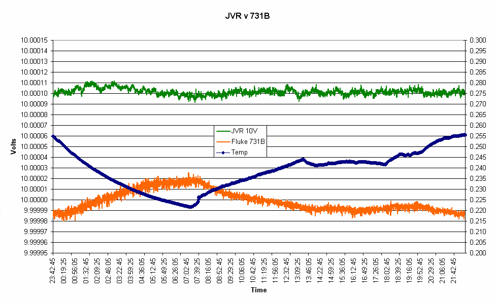
Another measurements before I take the JVR to the newly calibrated HP3458A. Taken with two Keithley 2015 and Keithley 617 as a thermometer (measuring the output of LM35D, 200mV = 20C, 10mV/degree, right scale). So far both JVR and Fluke 731B drifted less than 5ppm over the last year (even with all my attempts to measure a hysteresis). Interesting that the JVR has a low tempco between 22 and 26C
Cheers
Alex
Using the same jfet in plastic (to-92) case how worse could be the TC and long-term stability?
Could be a good idea to consider power jfet with lower on resistance then small jfet?
A plastic case JFET can have much higher long time drift due the humidity in the plastics. As this reference also needs a rather stable (and thus maybe more expensive than the FET) resistor, I see little sense in saving a little one the FET. The 2N4391-3 are still available in TO18 case.
A higher power FET could result in lower noise, just like using several in parallel.
Tomorrow will be two years since I've started this thread. The 10V JVR unit is back in the lab and connected to the HP3458A. The reference was not powered for two weeks in September when I was away for a holiday in Canadian Rockies and Vancouver. It was not affected much (if at all) over this time and came back to the exactly the same voltage as it was before the power interruption. The measured voltage today after 2h warm-up is 10.00008 V at 24C (previous measurements were taken at 25C). Overall, the drift of a complete reference (including the 7V to 10V amplifier part) appears to be less than 5ppm per year (+ whatever the meters uncertainty and drift is, so in total probably better than 10ppm/year ), measured by HP3458A Opt 002 and also compared with the Fluke 731B which looks very stable.
Cheers
Alex
Hi Alex,
I've read through the entire thread of this topic. You've got an excellent low-cost voltage reference design by the looks of it. I'm hunting down the parts to make my own now.
I was curious if you had had the time to make multiple copies of the same design to use as references against each other, or are you only using your fluke 731B for this purpose?
Thanks in advance
I'm using 731B, HP3458A and an LTZ1000 based reference for cross-checks. The HP3458A Opt 002 (4ppm/year) was calibrated in May this year.
I plan to make a proper pcb which would accept either a JFET or LM399 or LTZ1000, and will slide in a standard Hammond case.
Cheers
Alex
Sounds like a winning pcb. I've been following this too, and have some jfets ready to go. Can you make the pcb available on (for example) osh?
Per the ltz1000 I think you should stick to the datasheet circuit as opposed to the more elaborate KX one (my vote--obviously do what you like).
Thanks!
Is the schematic for the latest reference the same as the one in Reply #49 on Page 2, except with a 2N4391 JFET and an OPA227 OpAmp?
I would like to try building it.
Thanks for an interesting thread.
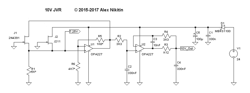
Here is the latest schematics (for the unit running for 2 years now). R1 is selected for the zero tempco point, R5 and R6 for 10V output.
Cheers
Alex
Hi Alex,
Is J2 used to start up the circuit? I'm assuming it pulls up the input of the op amp when power is applied, in order to generate a voltage to allow J1 to begin regulating.
Thanks in advance
 .
.