-
#100 Reply
Posted by
mimmus78
on 15 Jul, 2017 09:06
-
So my KX REFERENCE has turned 6m old. It's still stable in respect to my 3458a. I expected some seasonal drift but both 3458a and KX are still rock solid to the 0.3ppm.
Reference was almost constantly power on during this 6m and 3458a was used around 20% of time. As I already explained I noticed a 1ppm drift few months ago in both 3 reference, so this was connected to my 3458a that is still running hot.
I noticed this KX seems to drift up, while the other two LTZ reference exhibit the 1ppm down shift during first month as stated in datasheet.
Also my other two LTZ1000 references seems stable (but they are not constantly powered on) but in last months I didn't have much time to dedicate to this ...
Anyway what are changes from B01 to B03?
-
#101 Reply
Posted by
hwj-d
on 15 Jul, 2017 09:44
-
So my KX REFERENCE has turned 6m old. It's still stable in respect to my 3458a.
...
Are there somewhere photos in the forum i.e. which resistors you use? Thanks.
-
#102 Reply
Posted by
Andreas
on 15 Jul, 2017 16:18
-
I noticed this KX seems to drift up, while the other two LTZ reference exhibit the 1ppm down shift during first month as stated in datasheet.
Does it really drift up or only slower down than the other references.
Usually a LTZ drifts down.
The real drift can only be determined by comparison with official calibrated instruments over several years.
With best regards
Andreas
-
#103 Reply
Posted by
mimmus78
on 15 Jul, 2017 17:03
-
So my KX REFERENCE has turned 6m old. It's still stable in respect to my 3458a.
...
Are there somewhere photos in the forum i.e. which resistors you use? Thanks.
No I think I didn't have photos ... and I have no plans to open it right now.
Anyway I used many tht parts, so it's not to be taken as reference, nothing to be proud of and a little bit delicate too. I also think because of this is also almost unshippable without risking upsetting it.
I used LT1006 as op amp (single version of lt1013), Edwin resistors, it's buffered by a simple 2057, some caps and ferrite beads to avoid EMI.
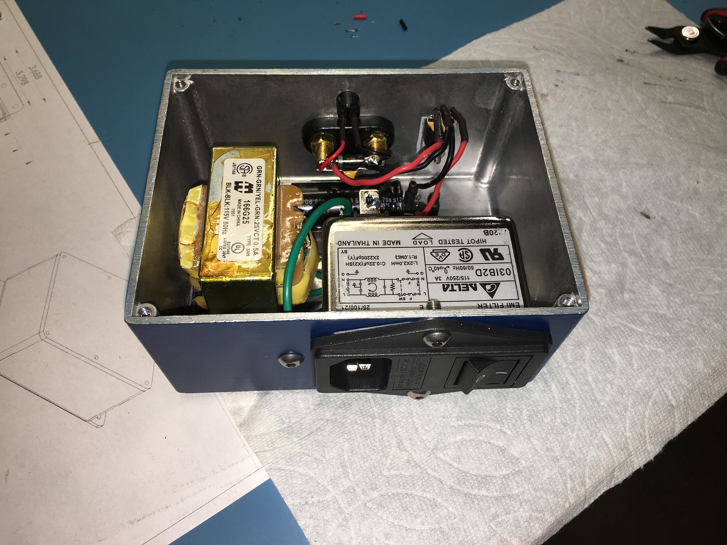
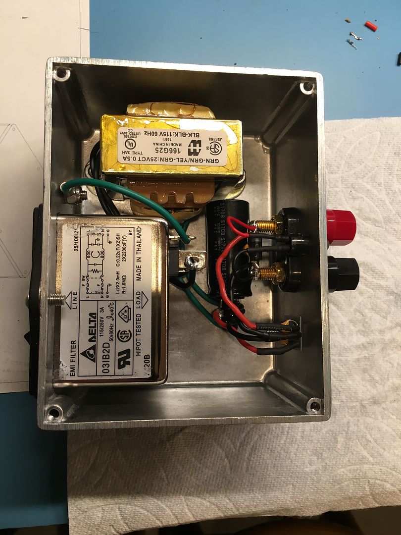
I used an external wall wart transformer (to avoid disturbances) and a 15V linear regulator inside the metallic case.
A small resistor was also added to add some more capacitative load driving capabilities after the buffer.
If you search among Andreas posts you'll find anything I did.
So my KX REFERENCE has turned 6m old. It's still stable in respect to my 3458a.
...
Are there somewhere photos in the forum i.e. which resistors you use? Thanks.
Inviato dal mio Nexus 6P utilizzando Tapatalk
-
#104 Reply
Posted by
mimmus78
on 15 Jul, 2017 17:06
-
I noticed this KX seems to drift up, while the other two LTZ reference exhibit the 1ppm down shift during first month as stated in datasheet.
Does it really drift up or only slower down than the other references.
Usually a LTZ drifts down.
The real drift can only be determined by comparison with official calibrated instruments over several years.
With best regards
Andreas
Andreas this is reason I added the word "it seems".
Inviato dal mio Nexus 6P utilizzando Tapatalk
-
#105 Reply
Posted by
TiN
on 16 Jul, 2017 22:53
-
I think it's all done for VK5RC's reference and it's ready to go now.
Here I cooked little
calibration report with the data I got.
-
#106 Reply
Posted by
kj7e
on 16 Jul, 2017 23:24
-
I think it's all done for VK5RC's reference and it's ready to go now.
Here I cooked little calibration report with the data I got.
Nice report!
-
#107 Reply
Posted by
Andreas
on 17 Jul, 2017 04:44
-
Hello Illya,
in the report you state 7K BMF in series with the reference for noise measurement.
Together with the 1K input resistance this will give a 8:1 voltage divider for the noise voltage.
Is this regarded on the measurement?
I usually short the series resistor after charging up the input capacitors of the noise amplifier.
With best regards
Andreas
-
#108 Reply
Posted by
VK5RC
on 17 Jul, 2017 07:32
-
Hi TiN,
Thank you for your efforts with this reference and publishing this and your other experiments results.
My 3458a is warming up, down here in south Australia the ambient air temp is not 24C at present, but I can reproduce this and other environmental conditions.
Over the weekend I had everything warmed up (22C), including the room everything is in, the 3458 and my 731 (both are pretty old) , I am getting results consistent with readings from 6 months ago to within 3uV.
The reference will be allowed to settle here for a while - while I check my dmms (3458, 3457, 34461) then off for a 'road trip' around the Aus Cal group, one has an 'in cal' Keithley 7510.
I think the best place to show the data will be on the Calibration Group post. I will post mine there and link to your results as well.
I was glad to see about 100 of your 'Kx babies' are out in the world! You should be a proud 'father'.
My next project (about 2/3 complete) is 6 Kx boards for a long term references study.
Again thanks,
Robert
VK5RC
-
#109 Reply
Posted by
Jon.C
on 18 Jul, 2017 12:28
-
hi
It is possible to buy all the components in a kit to mount ?
-
#110 Reply
Posted by
VK5RC
on 18 Jul, 2017 12:58
-
Hi Jon,
I know of no kit. You can assemble the bits yourself though.
xDevs (TiN) has on his website a list of the common parts from DigiKey - he even has the Digikey part numbers. Thanks TiN.
A PCB is available through OshPark PCB - see link on xDevs website.
The good resistors (the 120R, 1K, 70k x2 and the 12 to 13k) are the tricky part - Vishay's very good resistors are very expensive and hard to source easily esp in Australia, Mr Pettis (Ultrohm) USA has some very nice wire wounds for a very good price - he is busy. Some other wire wound resistors made by TE, model UPW50 can be sourced (In Australia) through RS components but to get the values a bit of mixing is required.
The LTZ1000 can be got through DigiKey, they have the C model in stock at present , I recently sourced some A models through TME. Others have got a few from the manufacturer directly - I have not done this. Cabling, mounting/boxing/insulation, power supply etc are other decisions
Half the 'fun' is researching what you want to get out of this, how much you want to spend, what you can get. I don't know what is available/import issues in your country - this can make a big difference on choices.
Every decision you make has some impact between $, long term stability, noise, ambient air temp etc. Look at the variation in the completed Kx references presented on this website to date - almost no 2 are identical.
Some of the serious Volt-Nut guys on this website have given a lot of time , experience and knowledge away - worth quite a bit of reading!
Regards Robert (volt-nut trainee!)
-
#111 Reply
Posted by
SvanGool
on 18 Jul, 2017 14:04
-
Not as good as Mr Pettis resistors and the Vishays, I found a supplier of NOS (New Old Stock) Sfernice RCK02 0.5W 5ppm/C (good enough for the LTZ1000) precision foil resistors who supplies directly from stock:
I have them here and they are fine, although you do have to bend, one of the leads, a little bit to fit the KX PCB.
Ready for action:

-
-
-
#113 Reply
Posted by
Kleinstein
on 18 Jul, 2017 19:15
-
PTF56 is lower price, but the drift and similar rating a about an order of magnitude worse than the foil resistors. I know comparing typical number is somewhat tricky and not that reliable - but at least in this case both number are from a common source.
For a reference used in a lab, the TC is usually not that important it is more about the less controlled parameters like humidity.
Drift of the PTF56 (e.g. 400 ppm load life, 800 ppm moisture) might be still visible after attenuation (factor 100-500) through the LTZ1000 circuit.
-
#114 Reply
Posted by
kj7e
on 23 Jul, 2017 20:37
-
-
#115 Reply
Posted by
Vgkid
on 23 Jul, 2017 21:17
-
Nice job.
Do you have a schematic for the heater?
-
#116 Reply
Posted by
kj7e
on 24 Jul, 2017 00:07
-
Nice job.
Do you have a schematic for the heater?
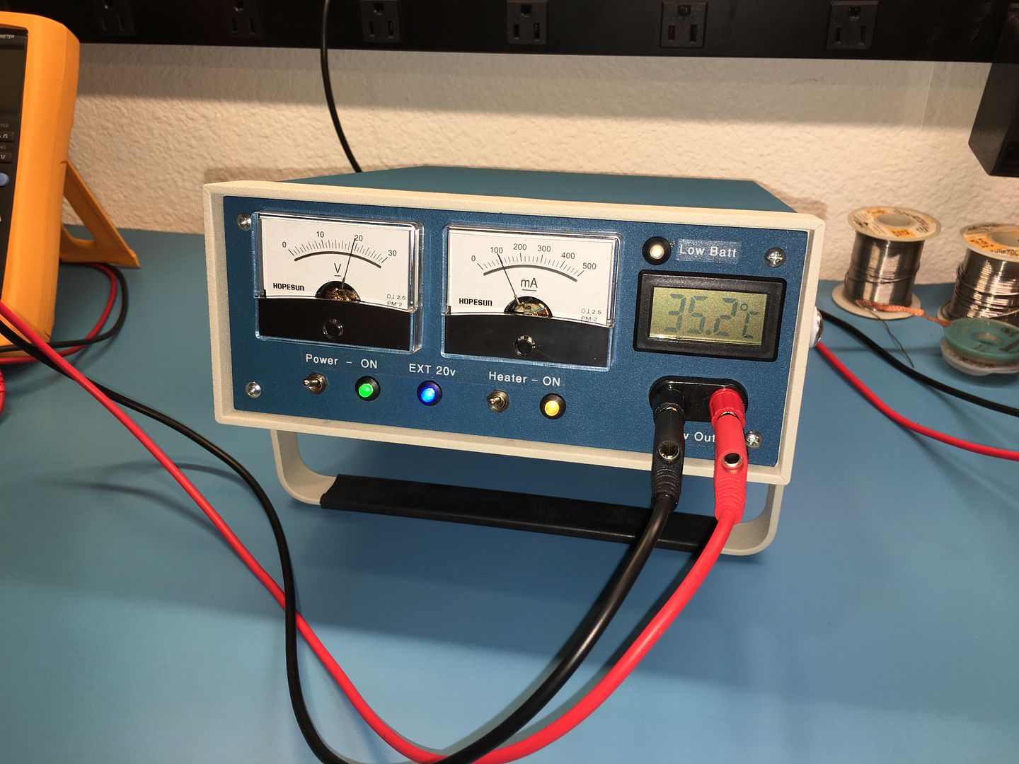
Back two pages, but I need to upload an updated version, slight changes, replaced the 499k negative feedback resistor for 2M Ohm for more gain (started to oscillate at 4M Ohm), also using a second 10K NTC disk type sensor in series with the oven chassis mounted sensor to better average the real internal air temp and the series resistor value was changed with the temp set pot due the second series temp sensor. The oven internal air temp stays within about 0.3 deg C from 15 deg C to 30 deg C ambient. About the best I could do with out going crazy. Have some thoughts on experimenting with an Arduino with both hysteresis and predictive compensation, maybe on v2.
-
#117 Reply
Posted by
Kleinstein
on 24 Jul, 2017 20:27
-
For good temperature regulation it would help if there is a temperature sensor relatively close to the heater. Fast reaction of the sensor help making the loop stable and thus allows a higher gain. It could also help to use an PI or maybe even PID regulator. One way to combine a sensor close to the heater and a second closer to the circuit is to use the first sensor for the P and D part and the second sensor for the I part only. However an analog PID could be tricky, due to the long time constants.
Another point is that the resistive heater makes it nonlinear. So the temperature regulator loop gain is higher, the higher the heater power. It would be possible to avoid this, by using the transistor as the heater instead of the resistors. As a side-effect this is also more energy efficient.
-
#118 Reply
Posted by
kj7e
on 24 Jul, 2017 21:45
-
For good temperature regulation it would help if there is a temperature sensor relatively close to the heater. Fast reaction of the sensor help making the loop stable and thus allows a higher gain. It could also help to use an PI or maybe even PID regulator. One way to combine a sensor close to the heater and a second closer to the circuit is to use the first sensor for the P and D part and the second sensor for the I part only. However an analog PID could be tricky, due to the long time constants.
Another point is that the resistive heater makes it nonlinear. So the temperature regulator loop gain is higher, the higher the heater power. It would be possible to avoid this, by using the transistor as the heater instead of the resistors. As a side-effect this is also more energy efficient.
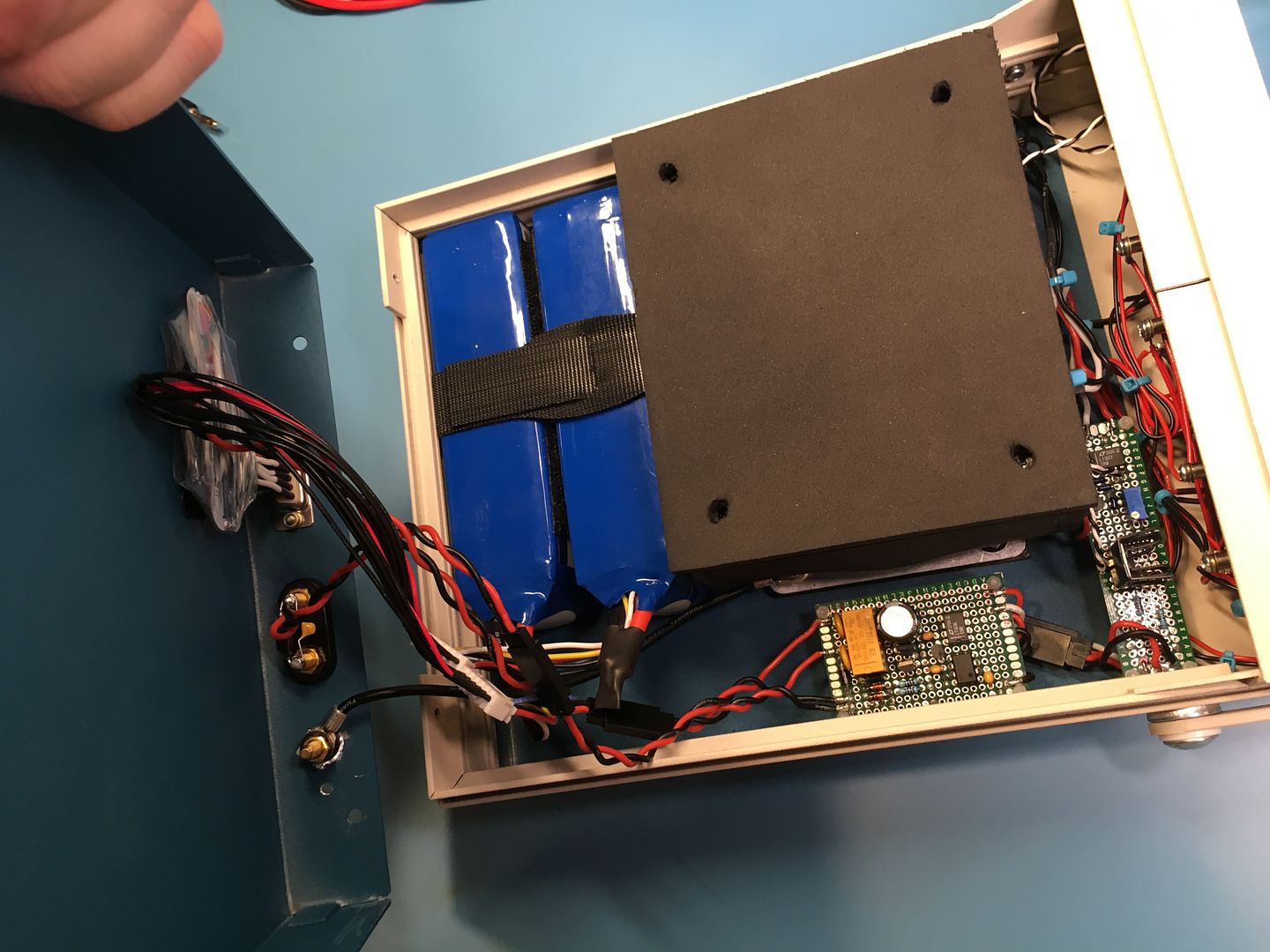
Yep, I found that out. Also mounted the heater element pass transistor to outside front of the oven for added efficiently and this also helps heat a third side. I had some extra 10K NTC sensors laying around so I started experimenting again today and may have made vast improvement. Currently, the heater resistors are on the ends | ----- | of the oven, one sensor was mounted just offset from the left resistor. This gave great and stable feedback and the area near the resistor stayed at a very consistent temp. Where I found some variation is with the internal air temp due to the top, bottom, front and back of the oven not being heated and only relying on the conductive heat from the left and right sides. Better insulation would help, but there is no more room for more insulation in the box. So my idea was to place the oven body temp sensor center bottom of the oven, this surface, while insulated, is in contact with the bottom cover of the box. I figured this area would be more representative of the internal air temp and the most effected by ambient change. So far I'm able to hold the internal air temp well within 0.1 dec C from the same 15-30 dec ambient. The downside is a bit more initial oscillation and time to stabilize, but it seems to be a good trade off. Ill post of some temp plots and sensor locations after more testing.
-
#119 Reply
Posted by
Kleinstein
on 25 Jul, 2017 07:20
-
I would consider a temperature stable to 0.1 C already quite good for a reference circuit that is by its own not very sensitive to temperature.
If one uses the transistor as a heater, it might be a good idea to replace the heater resistors also with constant voltage heater, like zener diodes or maybe a transistor in a VBE multiplier circuit. This way the distribution of the heat sources would be approximately fixed.
With better insulation, there is also a downside: the minimum temperature for the circuit will increase.
For monitoring the temperature of the reference circuit, one could watch the heater current needed by the LTZ1000 circuit. Ideally this would be constant at a not to low level - at low power levels the regulation of the LTZ1000 circuit is expected to get less accurate as the loop gain in going down.
-
-
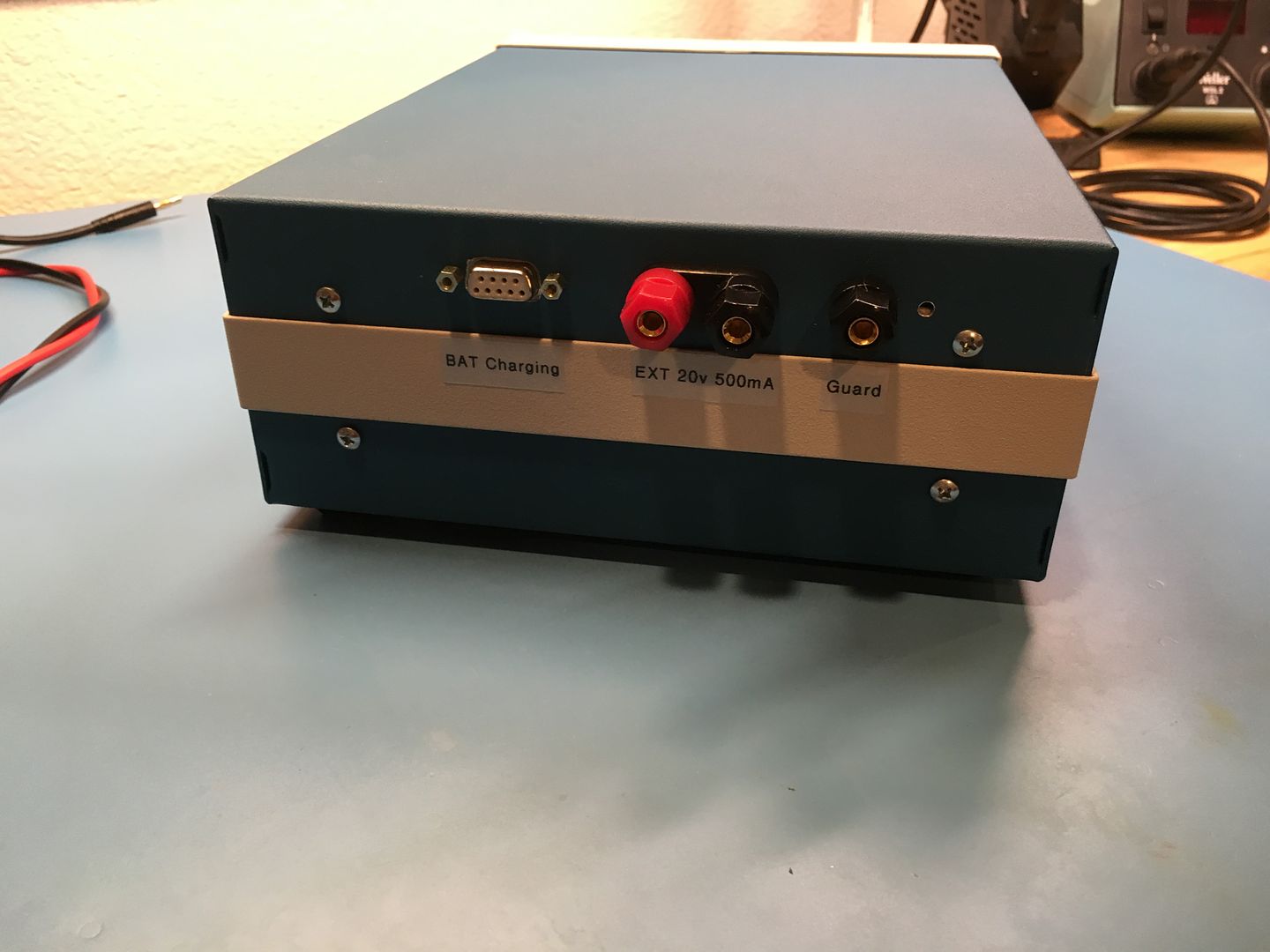
@kj7e, how do you transport the 10V dc from inside to outside the oven?
Long wires with the additional length coiled up inside and outside the oven to minimize temperature gradients across
the (inevitable) solder connections?
-
#121 Reply
Posted by
kj7e
on 25 Jul, 2017 14:38
-
@kj7e, how do you transport the 10V dc from inside to outside the oven?
Long wires with the additional length coiled up inside and outside the oven to minimize temperature gradients across
the (inevitable) solder connections?
That is a good question and one I have been wondering myself. After some further review I still feel the LTC1150/LT1010 buffer will suit me the best. The buffer board will be in the oven as well. From the buffer will be a pair of 24 awg solid copper ptfe twisted pair wires to the Pomona 3770 binding posts. One pair for the LT1010 10v output and one pair for the LTC1150 feedback or ratio set. Here is a diagram I found showing the buffer kelvin wires and ratio set (thank you Simon);
http://satcom.tonnarelli.com/files/LTZ1000A/NxtGenOpAmpBoard(RevA).pdfThe wires will pass though the oven via small holes with rubber grommets, there will be a few inches of wire in a semi coil to the front panel binding posts (see the third photo down in my post above) to facilitate assembly/disassembly and maintenance. I know there will be a slight temp gradient from the oven to the binding posts. What I don't yet understand well is how to best minimize the thermal emf between the output and binding posts. Such as, if the thermal gradient is minimized in solid copper wire from one solder point to the next, will that effectively minimize the thermal emf? I have some reading to do.
-
#122 Reply
Posted by
Kleinstein
on 25 Jul, 2017 15:10
-
For the thermal emf it depends on the material where the the temperature gradient is in. So ideally there will be a relatively long copper wire (e.g. twisted pair) from the oven to the outside, with quite some length of wire with good thermal contact both in the oven and at the outside near the terminals. So the setup seems to already quite good. Usually there should be no need for Teflon isolation, as the lines are low impedance. If paranoid or in a really sensitive circuit like a nV amplifier one should avoid bending the wires in the temperature gradient part. In case of separate drive and sense lines, it is the thermal emf in the sense lines that matters.
Normally I would avoid having the buffer inside the oven - it adds extra power and a good buffer should be stable even without a stable temperature. However the place inside might be more convenient for EMI reasons. If there is 7 to 10 V scaling, it is of cause important to have at least the resistors at constant temperature. However in this case is might be convenient to have both a 7 V and a 10 V output.
The amplifier circuit linked is sensitive to extra resistance in the sense wires. So one might have to find a good compromise in wire length between the extra resistance and thermal emf errors. One might consider unequal lengths of wire, so to get the same about 2:1 ration for the resistance. One also has to take care about the supply current (especially for the reference) - it might need an extra current compensation.
-
#123 Reply
Posted by
hwj-d
on 27 Jul, 2017 14:35
-
At this point a lightly philosophical question:
Why or for what we need this special exact 10V output there?
Isn't it better to let the generated 7.xxxxxxxxxxxV be there as buffered output as it is, but instead build a additionally ADC DAC buffered precise output for variable voltages as we need in real live, like IanJ with his PDVS2 does?
-
#124 Reply
Posted by
Echo88
on 27 Jul, 2017 20:29
-
Youre right that the 7.xV output is more stable, but with 10V you can (theoretically!) calibrate a 3458A and its a nice round value to work with. You mean a PWM-based DAC like the Fluke 5700 PWM-DAC? Thats a glorious design for sure. But nobody has yet designed a open source pcb based on it. Apart from the fact that it doesnt produce a 10V as stable over time as a Datron 4910-Design for example.