You can calibrate 3458 off 7.xx volt too.
Correct - in the real world you want an LTZ to provide a very stable non-zero voltage reference, anything you do to that Vref to boost or attenuate that reference is going to add noise, drift and overall instability. We find that we need a meaningless 10V cardinal point less and less - although it is very important to know WHAT absolute value you have on your Vref.
Again: The LTZ circuit is really very easy compared to an ultra-stable 10V boost circuit (732a/b level) - normally if you're dealing with ADC's or DAC you want to divide the 7.XXXXX zener voltage, not boost it. Boost circuits will always tend to add more drift and noise no matter what, because generally you're gaining up any circuit errors. Just depends on what your application needs.
If you really -need- a 10V calibration reference, it's much easier, reliable and profitable to just use (or rent or borrow) a calibrated 732a/b - and keep it calibrated - if your time is worth anything and you're on the clock. I know it's not as fun, but that's reality. Especially if you have to pass an ISO900x audit: a self built reference (non-JJA) will probably never pass muster anyway (not for less $$$ than a 732), no matter how good it is.
You can calibrate 3458 off 7.xx volt too.
Does anyone know if Fluke 5440B (I'm now repairing one, will take a while, some DIY needed) can also accept 7.x for the external 10V cal? In the operator and service manuals it only says:
If the voltage standard is not exactly 10V, the exact value may be entered at this time with the numeric DATA ENTRY keys.
But I have no idea if the software imposes limits (e.g. only from 9 to 11V).
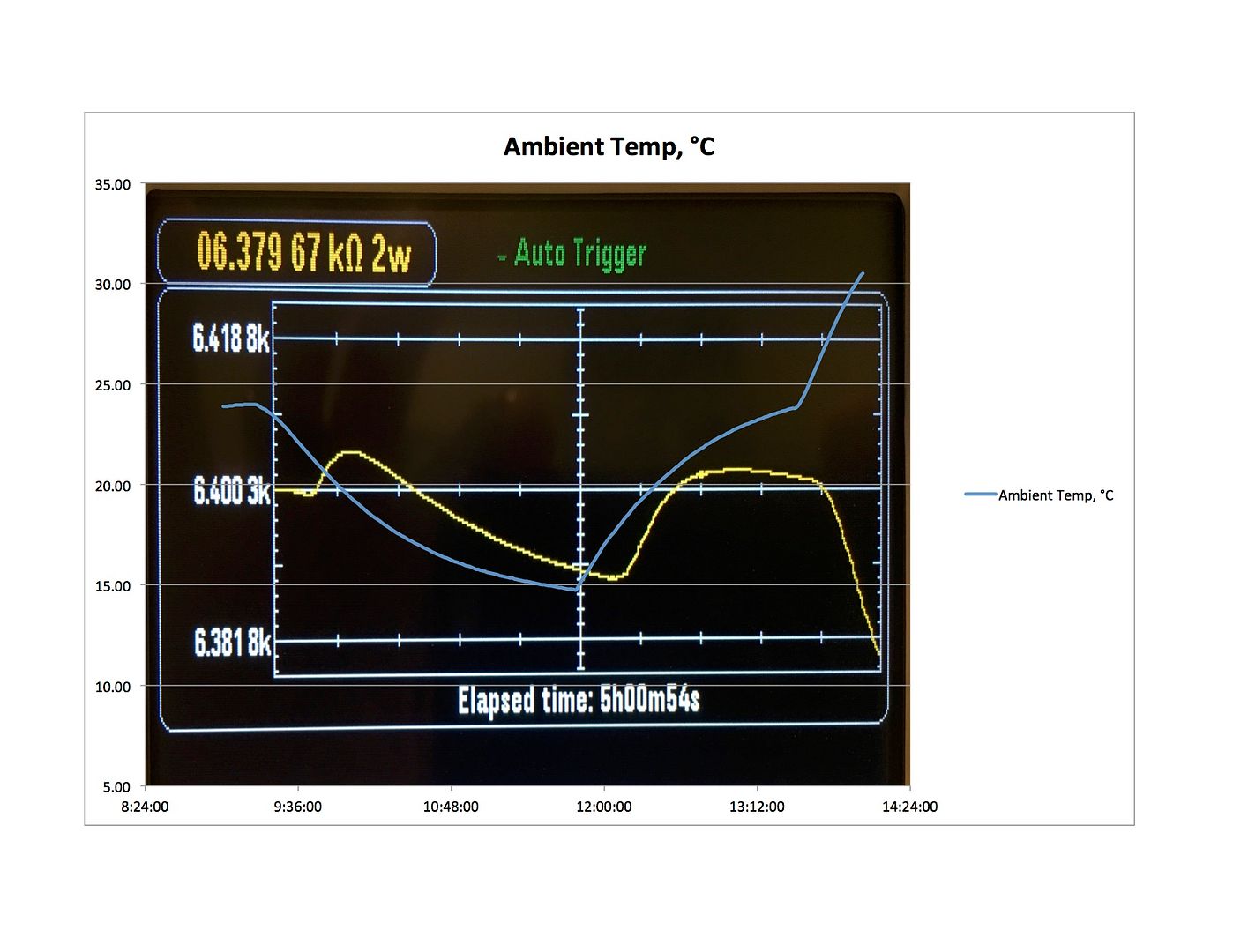
Full scale on the 34465a is 27 Ohm, with the 10K thermistor (U.S. Sensor USP10976) this comes to ~0.1 deg C full scale. Internal oven air temp vs external ambient air temp, starts at 24 deg C ambient at 9am. As the ambient temp started to drop so did the internal air temp, but only by about +5 Ohm or -0.02 deg C at the 35 min mark. As the ambient temp fell further down to 15 deg C at 12pm the internal air temp raised by -10.5 Ohm or + 0.04 deg C. The climb back to room temp shows a slight negative overshoot with the internal before the steep rise in internal temp as the external ambient temp climbed over 30 deg C, however still staying within +.05 deg C. So 15 deg C to 30 deg C ambient the internal air temp is within + or - 0.1 deg C, close enough. Note, the two plots are askew time wise.
About 15 weeks after my order, look what showed up yesterday;
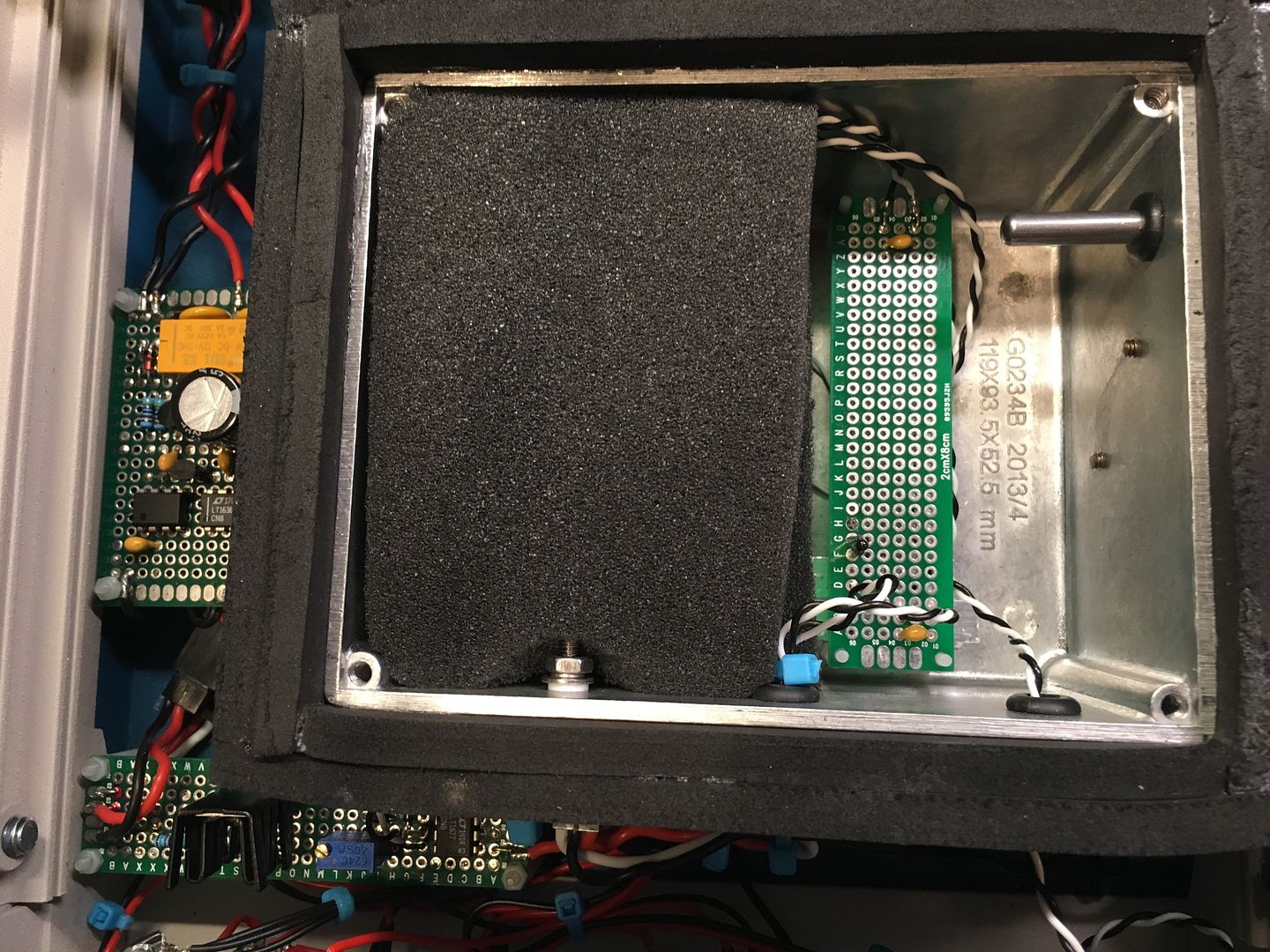
I revised my mounting method and carved out some open cell foam;
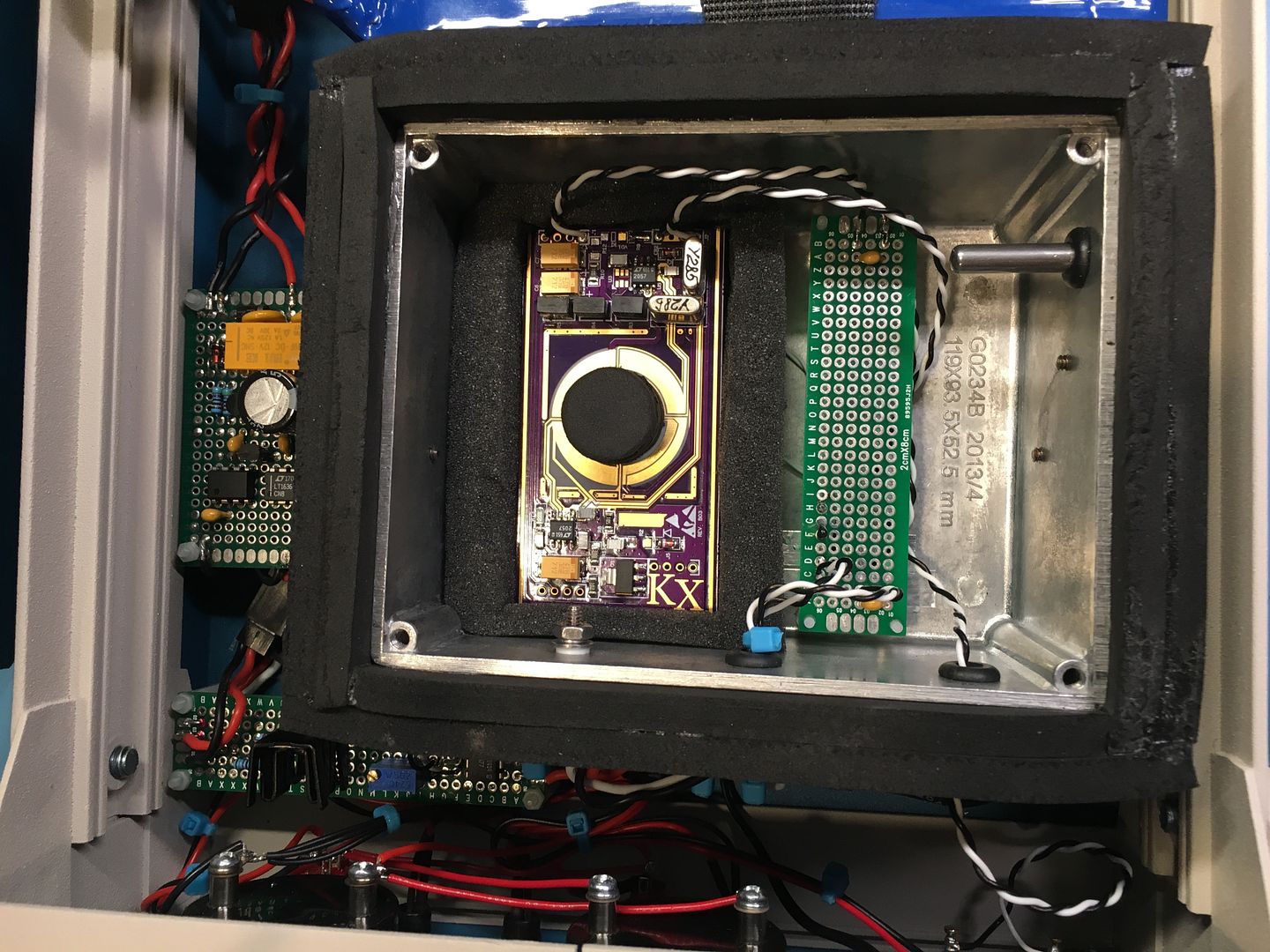
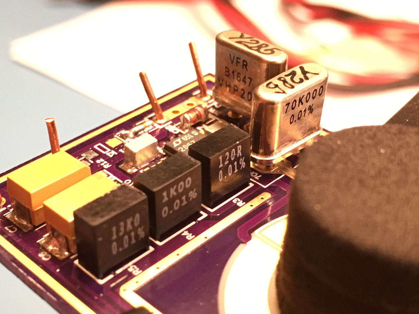
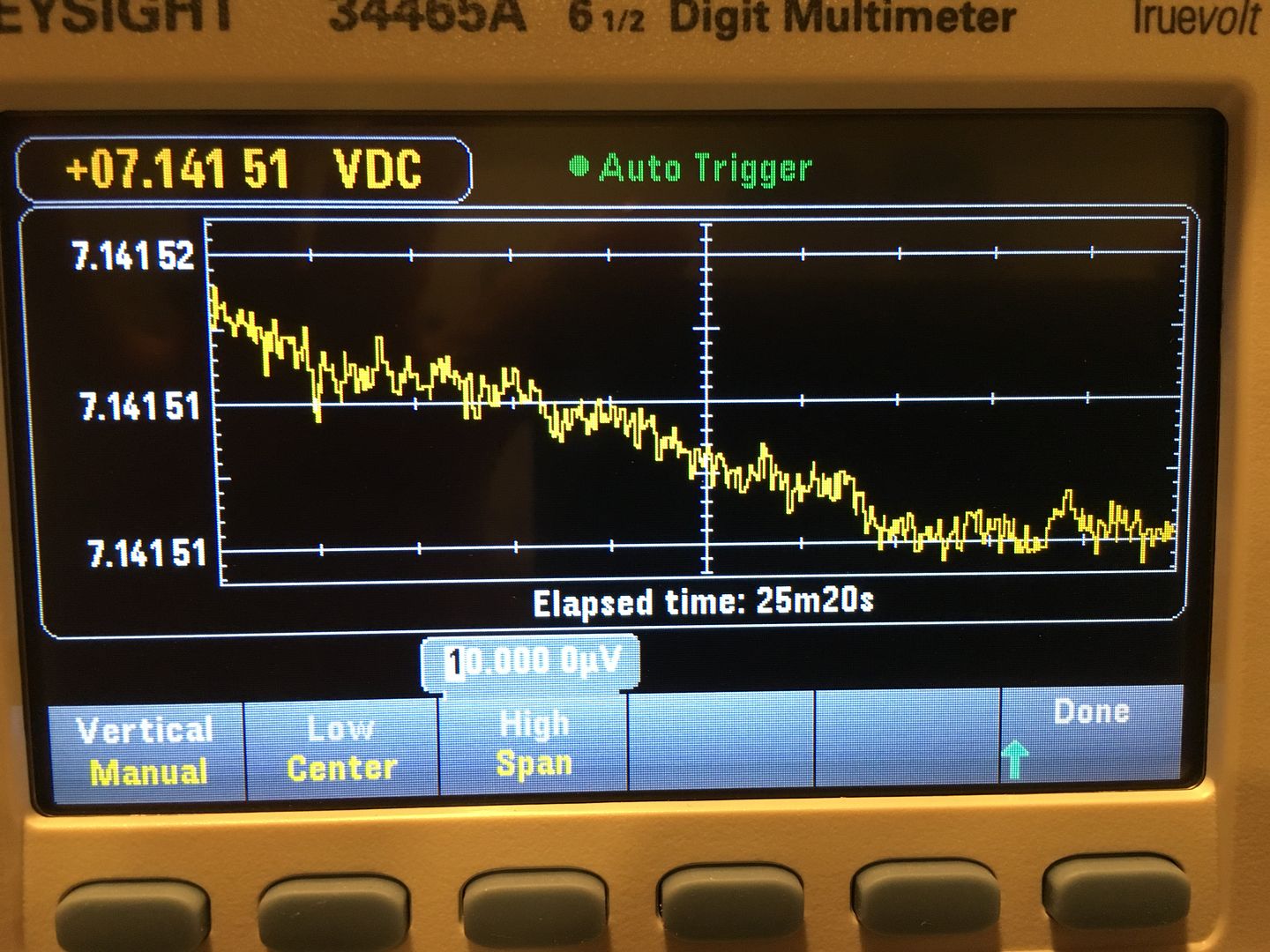
With the proper resistors, the voltage is now 7.14150, up from 7.13358 where it has been burning in for the last two months. I noticed no real change or drift from 25 deg C with the oven off to 35 deg C with the oven on. Now I have the proper voltage, I can order the resistor network for the buffer.
I don't need 10v for any specific reason, I don't even need this reference to to tell you the truth. This is just a project I wanted to build, for the fun of it.
It's been almost a month since I ordered a LTZ1000A for my 2nd LTZ1000A reference, and it still hasn't shipped. Looks like they are really out of stock.

It's been almost a month since I ordered a LTZ1000A for my 2nd LTZ1000A reference, and it still hasn't shipped. Looks like they are really out of stock. 
Through Digikey? They say ship date for the "A" is Sep 16th, they have the non "A" in stock.
It's been almost a month since I ordered a LTZ1000A for my 2nd LTZ1000A reference, and it still hasn't shipped. Looks like they are really out of stock. 
Through Digikey? They say ship date for the "A" is Sep 16th, they have the non "A" in stock.
From LT directly. Yeah I know non A is in stock, I wanted to build an A version, since I already have an non-A one.
Re LTZ 1000A, I got one from TME, a bit more than Digikey but posted really quickly.
I have a nice TE, PTFE socket for the LTZ1000 if you want it. Also one extra KX board.
One hour plot of the KX LTZ1000A with the Keysight 34465A (best I have). I was fighting Excel trying to get both plots on the same chart, I was spending too much time on and gave up. All this shows is the tempco sensitivity of the 34465A. Hard to keep the room any more consistent in temp, the LTZ1000A was held steady at 35 deg C while the 34465A was subject to the ambient temp.
@TiN,
I'm seeing 7 to 8uV downward drift as the KX reference warms up from 20 deg C to 35 deg C, is that about whats expected or does that seem excessive? Reading back to your post about VK5RC's board, one of the tempco improvements you made was with dropping the chip to the board. I'm wondering if I should do the same now. If I take 0.05ppm/C I should see less than 6uV for 15 deg C change.
The 7-8 µV are about the normal order of magnitude, though it can depend on the resistors used. In the unit with extra temperature stabilization this is not at all problem, as the more normal temperature change will be much smaller.
The change in TC when changing from some distance to the board to short pins is somewhat predictable. So before shortening the pins one should look at the sign of the TC, as the small change could also be to the wrong direction. I think Andreas did a few tests on the TC with short and long pins.
I remember reading about that when I was searching for lead length info some months back. It was discussed around here;
https://www.eevblog.com/forum/metrology/ultra-precision-reference-ltz1000/msg928435/#msg928435It seems, the shorter leads reduce the downward drift with rising temp. My chip is maybe 1.5mm above the board now, so I could shorten the leads some. First I'm going to see if the drift is repeatable a few times then I think I'll try trimming the leads.
With very short leads, there is also more transfer of board stress towards the reference. The linked thread also has the comment that a 1 mm spacing is suggested. So not very much change from the now 1.5 mm. So I would not bother and not add new stress from soldering. The extra box with heats should reduce external temperature variation quite a lot - cold be about a factor of 100 if I understand the curves right. So the TC of the reference is less critical than in a normal circuit without the extra heater.
The downside of the external heat is that the internal heater is working at a relatively low power level. Due to the square law heater this means slightly less accurate temperature regulation. So one might be tempted to slightly adjust the temperature regulation circuit for better operation at low power: Increase the loop gain and add some kind of nonlinear approximation of the square root function to reduce the gain again at high power.
A few quick thoughts:
A) With that meter and temperature range, you have to allow for the meter drift that takes place over the same time and temp range. I don't think you're measuring accurate uV like you think you are - but otherwise nothing to be alarmed about. Look out also for thermals and offsets developing across every connection while ambient conditions change. You'll want an equipment upgrade in the future to chase into low PPM territory like you want to - this is where nulling against a stable Vref/s like 732a/b + KVD + null meter can help you get down into the finer details of accurate lower ppm measures better and faster than a DMM. Heck, you can grab a couple null measures against a couple 732's just while a 3458a is still running AutoCal

We use all techniques though to get the best quality measure.
Lead length should make no huge difference on "A" version in terms of board stress - the leads are fairly isolated from board stress with the wire bond layout inside that package - that's another change request by HP for the "A" version decades ago. The non A version might be a bit more tender; we never use those. We just put those "A" right down onto the PCB, and we don't run them especially cold either - they are fine after decades (13k over 1k minimum heater resistor ratio). What you can have happen is -any- exposed lead length can make a spot where air currents cause all sorts of problems. You want that package protected from air currents, especially the leads (top and bottom). That is not the same thing as over-insulating it, which is worse.
B) I wouldn't ever use sockets unless you want to just do a quickie initial parts test.
C) Watch out for eBay suppliers of LTZ. For the cost of the rest of the system I'd just go with ordering from LT direct - yes it takes several weeks sometimes but that's lowest risk. Right now there are zero eBay suppliers selling -confirmed- factory prime parts...everything you see listed is some sort of floor sweeping reject. They might work or they might be out of spec. For the cost of the parts I want to give it best chance at lowest risk. Right now LT direct is quoting del'y about September or so.
I'm seeing 7 to 8uV downward drift as the KX reference warms up from 20 deg C to 35 deg C,
Hmm,
is this the drift of the zener or from the DMM (warm up drift) or some ageing drift?
I usually do a complete temperature cycle to see if there is something fishy in the measurement setup.
And from the 5 connected measurement devices sometimes there is one which does not agree to the others.
with best regards
Andreas
The DMM has been powered on for 21 days and is staying within 0.5 deg C while the KX-LTZ1000A board is cycling between 20 to 35 deg C. The downward drift is repeatable and appears to be the LTZ1000A and not the DMM, however my subsequent tests show about 6 uV (slightly less) downward drift with rising temp. I realize I'm trying to measure beyond the realistic ability of my equipment. Its still fun non-the-less. I do want to try and shorten the leads, but as already mentioned above I may do more harm than good.
You are building a very nice reference device. Thank you for sharing this.

About your TC. I've seen 10µV at the y-achsis, right? You have 0.4ppm TC at this moment. I think, that's ok?
But think about, yo're looking to your measurement system
incl. your 34465a and your
long measurement lines. I know, my Keysight is
very sensitive to ambient room temperature too. I use preferably short cat6 twistet
and shielded lines. If i touch them, it has directly impact to the measurement. Also i'm watching a direct TC change proportionate to room temperature
and if i'm sitting in front of this or not.
Best regards
Thank you hwj-d.
Yes, I can watch the 34465a draw sine waves with the A/C cycling. However, I have been able to reliably duplicate the T/C drift of the my KX board. Some of this may be due to thermal EMF from the junction in the oven to the front panel banana plugs? In any event, I'm going to build a second KX board, this time I was a bit more careful and clean with my assembly of the SMD components and will take a bit more care with heat sinking the sensitive parts. Ill be interested to see if one will test better or not. If not, then I have my answer. When I'm happy with it, I hope to send it off to someone for a better measurement than I can perform with my gear.
If i touch them, it has directly impact to the measurement.
Is the change immediately = capacitive influence
or slowly rising / falling = thermal offset?
With best regards
Andreas
0.4ppm/K tempco is more than 8 times worse than expected (<0.05), so there is definately a system problem. Is your PCB version B03? There was issue with routing on earlier B01, that affected tempco. You may want to test tempco of your 34465A to establish the measurement stability true value. Just keep LTZ ref at constant temp, and variate meter temp (e.g. insulate it in blanket with temp sensor fixed to a meter). Do it few times, and once you get the meter tempco , you can try again to measure LTZ's output tempco.
Also connections and unshielded wires can easily create more noise/offsets than tempco itself, hiding all as higher "appartent" data. Even copper-copper connection junction still have non-zero temperature coefficient.


 We use all techniques though to get the best quality measure.