-
My short review of the SPD3303D:
The test in the video starts with a serious problem on channel 3, with the fixed voltages output: there are big voltage spikes (up to 7V), even with load, if you turn it on or off. And it overshoots, if you short the output. UPDATE: see here how to fix these problems.
But there were no problems on channel 1 and channel 2 and it can be even used for a hand drill.
I opened the case at the end of the video, but it is not a full teardown and very short, because I don't know much about analog electronics anyway.
Not shown in the video:- one hour load test with 8 ohm on channel 1 and channel 2 each, and 2 ohm on channel 3. The fan starts, not too loud, and the power supply survived it
- if you want to use the PC software, you have to instal the NI environment first: http://joule.ni.com/nidu/cds/view/p/id/4230/lang/en (the registration doesn't need eMail confirmation, so enter what you want)
- I've tested the channel 3 a bit more, and on the 5V selection there is a voltage of 82mV when turned off, 48 mV for 3.3V and 46 mV for the 2.5V selection. Can be loaded with 2 ohms, still there.
- problem with "all on/off": if e.g. channel 1 is on, channel 2 and 3 are off, and then I press "all on/off", it turns all channels on. I would expect that it turns any channel off, which is on, but maybe it is just me who is surprised by this feature

- lock-key: in lock-mode, it is still possible to change the voltage from the PC
- parallel and series mode: in parallel mode, channel 1 and channel 2 are parallel (and available at the terminals at channel 1), for currents up to 6.4A, and in series mode channel 1 and channel 2 are linked in series (and available at the negative terminal of channel 1 and the positive terminal at channel 2), for voltages up to 64V. Unfortunately it is just a relay internally, the display doesn't sum the voltage or the current and it is the same, as if you would link it externally (which is possible, too, because the channels are all independent of each other)
- wave display: this shows a waveform of the voltage and current. Can be enabled individually for each channel. It is difficult to read, because there are no scale lines and it has no auto-scaling.
Discussion about my power resistors and some more ideas for cheap homebrew dummy loads:
https://www.eevblog.com/forum/testgear/power-resistor-dummy-load-for-psu-testing/
The stackable cables with banana plugs are from this eBay shop:
http://stores.ebay.de/chr
I'm not affiliated with this seller, but I have bought such cables from other sellers and they were very bad, with thin wires with an iron/copper alloy and not very solid plugs. So maybe this is useful, if someone wants to buy good cables.
High resolution photos:
logic board, left side
logic board, right side, far focus
logic board, right side, near focus
mains switch
regulator board, left side (there is some rust)
regulator board, right side
top view, back
top view, front
top view, left
top view, right
The mosfets on the heatsinks are IRFP150N. There are two of them on the right heatsink, but only one on the left heatsink, and looks like a temperature sensor is mounted instead on one heatsink. And there is another big 4 leg IC on each heatsink, which has no label (doesn't look like it was sanded, just mounted the wrong way on the heatsink). On the logic board the main microcontroller is a STM32F103. There are some PC817 photocouplers and some JQC-3FF relays.
-
It's like... I do not need any color LCD, give me a simple PSU with no spikes and no other HW problems. I have heard good things about Statron PSU. http://www.statron.de/details/19
http://www.statron.de/details/306
I love the 1980's style. But yes, these PSUs are manufactured today.
-
I've used a Statron at a client, good quality, I like the multi-turn potentiometer for the voltage. But you can't control it from a PC, which is useful for some applications, if you write your own programs to control and monitor it.
For example once I helped working on a watchdog problem, where once in a while a device reseted right at boot. To see if the problem was fixed, a complicated setup was built, with an external relay to switch a power supply. Would be just a few lines of code with a power supply with USB, and you can detect a successful booting by reading the current consumption with one of the USB commands, or by combining the code with which controls the power supply with some readings from the serial port of the DUT. -
[..] parallel and series mode: in parallel mode, channel 1 and channel 2 are parallel (and available at the terminals at channel 1), for currents up to 6.4A, and in series mode channel 1 and channel 2 are linked in series (and available at the negative terminal of channel 1 and the positive terminal at channel 2), for voltages up to 64V. Unfortunately it is just a relay internally, the display doesn't sum the voltage or the current and it is the same, as if you would link it externally (which is possible, too, because the channels are all independent of each other)[..]
It's not exactly just a relay. The channels are actually being put in tracking mode by software so their control loop controls are tied together (with "slave" following the "master"). It wouldn't work that way if the firmware wasn't "aware" of the serial/parallel mode you're currently in. It's only the actual summing of readings what it doesn't do for you. -
This (I hope) isn't a silly question ..... but how hard can it be to design a PS WITHOUT a turn on spike?!?!?!?
-
I'd just like to add few things about my SPD3303S which I like more in comparison to Rigol DP832 (not having one, based on what I read and saw here): *)
- I like the red/green LED indicators of CC/CV operation directly above the relevant channel. It seems intuitive to me and it is what I'm used to after my (brief) encounters with other/older supplies.
- It seems all the electrolytics are Rubycons.
- I like the mains power switch better. The Rigol rocker type one seems "cheap" to me and not really appropriate for the purpose.
- It's much shorter and I like the simple "blocky" design.
After inspecting stills from Frank's brief "case open" presentation (thank you and can we have some HQ photos, pretty please?After FrankBuss posted some more details it seems I was wrong on that one. ) it seems there are at least two pass transistors per each of the main channels which is a good thing thermal-wise and less prone to some borderline thermal dissipation issues, I guess?
- All channels are isolated. I must admit I haven't checked that but I assume the manual doesn't lie about it.
What I like less but think I can live with (again, comparing to Rigol DP832):- No numeric keypad of any kind - you have to dial the parameters in using the encoder.
- Third channel being fixed 2.5V/3.3V/5V only. Not really that big of a deal for me as I mostly work with digital so I can almost always power the logic with one of those.
- No voltage or current reading for third channel whatsoever. I think this could be a deal breaker for some and almost makes you think the third channel was a kind of an afterthought. But personally I imagine inspecting my new circuit carefully using one of the main metered outputs and not caring about the readings that much afterwards after I already know what to expect.
- I can imagine situations where hard current limit (in contrast to CC mode) would come handy but sadly, you won't find it here.
*) Disclaimer:
I have no intention of proving anything to anyone (including myself). It's just because Rigol 832 is kind of a hot topic here as of recently and just maybe my post will help someone with his/hers buying decision. -
I just checked the isolation of the three channels: first I measured it with an ohm meter, then wiring channels 1&2 in series, 1&3 in series and 2&3 in series. For all tests I loaded it with 8 ohm. Looks like it worked, the voltage was as expected.
-
Yes, the Statron looks like it was developed in mid 1980s.
-
The warranty seal is broken anyway, so I've updated my first posting with some photos.
-
The warranty seal is broken anyway, so I've updated my first posting with some photos.
Cool! Thank you, FrankBuss. -
And there is another big 4 leg IC on each heatsink, which has no label (doesn't look like it was sanded, just mounted the wrong way on the heatsink).
I think that would be the rectifier bridge. -
I've done some scope plots for the problem on channel 3 and sent it to the support. It doesn't need to be a problem of the PSU in general, maybe my unit is just broken, but I doubt it. Maybe someone can verify it with his/her unit, if you have the same PSU?
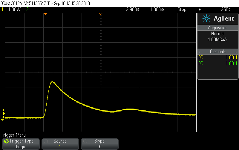
I loaded channel 3 with an 8 ohm resistor, then I turned the PSU on with the power-switch (the PSU was turned off a few hours before). As you can see, there is a 1.5V spike, falling down over some milliseconds (1V and 1ms per division). The voltage selection for channel 3 was on 5V. If I turn it off for just a minute, and then on again, the spike can be even higher, I've measured up to 7V. There should be no voltage at all, because the channel is turned off initially when I turn on the PSU.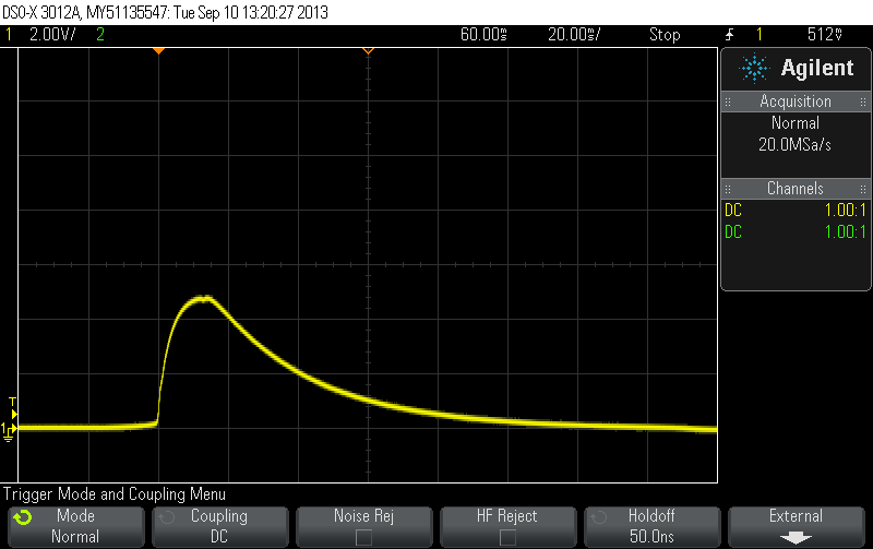
Same setup, this is what I see when I turn it off with the power-switch, and channel 3 still not enabled. A big 5V spike, falling over 100ms. And this is at 0,6A, because of the 8 ohm load. A sensitive DUT could be destroyed by it.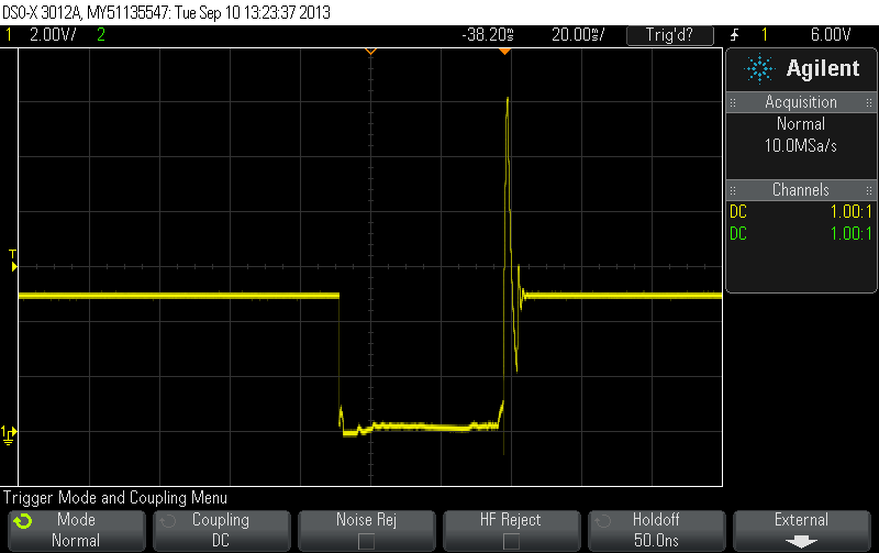
Same setup, channel 3 loaded with 8 ohm, the channel output was turned on with the CH3-ON/OFF switch, and then I shorted the output. As you can see, there are some serious overshoots, up to 12V! If I have a sensitive DUT attached and accidentally short the power supply outputs momentary, it could be destroyed by such overshooting. I don't trust this output at all anymore, because maybe there are some other overshoots, depending on the dynamic behavior of the DUT.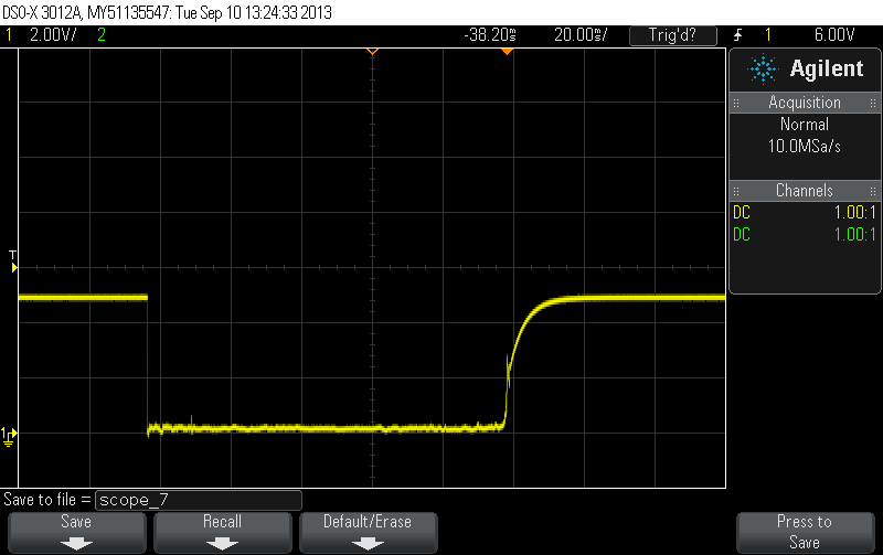
Just for comparing this with the other channels and to verify my measurements: same setup, but this time for channel 2 (8 ohm load, turned on). I shorted it momentary, as with the test for channel 3. As you can see, nice regulation without overshooting. Same for channel 1, no problems.
-
I've done some scope plots for the problem on channel 3 and sent it to the support. It doesn't need to be a problem of the PSU in general, maybe my unit is just broken, but I doubt it. Maybe someone can verify it with his/her unit, if you have the same PSU?
As I have already reported in some SPD3303 threads before, I too have a voltage spike on CH3. I have SPD3303S HW ver. 1.0. It goes up to 12V on mine. I haven't tested the overload recovery overshoot. I can post some oscillograms later. -
As I have already reported in some SPD3303 threads before, I too have a voltage spike on CH3. I have SPD3303S HW ver. 1.0. It goes up to 12V on mine. I haven't tested the overload recovery overshoot. I can post some oscillograms later.
Thanks, so my unit is not broken. I hope they know a fix, or we have to reverse engineering the circuit and try to fix it ourselves
-
I miss a numeric keyboard on this Siglent PSU. Even some old PSUs have it.
-
Thanks, so my unit is not broken. I hope they know a fix, or we have to reverse engineering the circuit and try to fix it ourselves
Yeah, would be great if they come with a fix for this. But when it comes to messing around with it by myslef, I think I'd just rather learn to disconnect my DUT physically first before turning the power off and vice versa. Now, that recovery overshoot could be another story, I wasn't aware of that... -
I miss a numeric keyboard on this Siglent PSU. Even some old PSUs have it.
Well, the one on your photo doesn't have any knob so it better have some way of selecting the voltage ;-) I too wouldn't mind additional numeric keypad but it's not a deal breaker for me in any way. I imagine this could even be safer sometimes as it's much easier to accidentaly punch in 29V instead of 2.9V than to accidentally crank it up all the way up with a knob. -
As promised, I attach my results (SPD3303S, HW1.0)
-
Looks very similar to my oscillograms, and I can confirm your examples with no load, the impulses are longer. This is a confirmation that it is a design bug. Or a series production error, some wrong components.
-
abo !
Frank, Thanks for the review. Exactly what I was looking for.
As I saw, you bought this PSU on ebay.
I am fighting with myself since more the 3 weeks to not buy ... still fighting
Regading the spikes: would a big capacitor help, something like 4700µ or so ?
EDIT: forgot to ask: is this thing hackable? I mean that you get an S model with a simple hack? I can not imagine that they have build something different. -
Regading the spikes: would a big capacitor help, something like 4700µ or so ?
I don't know. But meanwhile the support sent me a description how to fix it, with soldering and replacing some new parts inside (all standard parts which you can get at Digikey or Farnell). There were some inconsistencies between the parts I can see on the image they sent, and what they described in the repair text what I should use, but as soon as this is resolved, I'll try it and then publish the results here, and the description of the fix, if Siglent don't mind (they sent me a nice board screenshot from their CAD program with top/bottom side traces and annotations how to fix it).EDIT: forgot to ask: is this thing hackable? I mean that you get an S model with a simple hack? I can not imagine that they have build something different.
Maybe, but why do you need a higher resolution than 10mV/10mA? There are no separate sense inputs, so depending on the length of the cables and the current, the voltage at your breadboard might be off by several millivolts anyway, because there are no external sense inputs, and I don't know an application where I would need to set the current limit with higher resolution. -
Regading the spikes: would a big capacitor help, something like 4700µ or so ?
I don't know. But meanwhile the support sent me a description how to fix it, with soldering and replacing some new parts inside (all standard parts which you can get at Digikey or Farnell). There were some inconsistencies between the parts I can see on the image they sent, and what they described in the repair text what I should use, but as soon as this is resolved, I'll try it and then publish the results here, and the description of the fix, if Siglent don't mind (they sent me a nice board screenshot from their CAD program with top/bottom side traces and annotations how to fix it).
nice, would be interessed in what they do. If you are allowed, maybe you can post it here.EDIT: forgot to ask: is this thing hackable? I mean that you get an S model with a simple hack? I can not imagine that they have build something different.
Maybe, but why do you need a higher resolution than 10mV/10mA? There are no separate sense inputs, so depending on the length of the cables and the current, the voltage at your breadboard might be off by several millivolts anyway, because there are no external sense inputs, and I don't know an application where I would need to set the current limit with higher resolution.
10mV is in fact sufficient, but because it's fun and it does not hurt to have the ability to change in 1mV ;-) I also assume that there is a kind of linux there.. then you can add for example ethernet interface etc.
-
I don't know. But meanwhile the support sent me a description how to fix it, with soldering and replacing some new parts inside (all standard parts which you can get at Digikey or Farnell). There were some inconsistencies between the parts I can see on the image they sent, and what they described in the repair text what I should use, but as soon as this is resolved, I'll try it and then publish the results here, and the description of the fix, if Siglent don't mind (they sent me a nice board screenshot from their CAD program with top/bottom side traces and annotations how to fix it).
That's great news. Looking forward for your update on that matter. -
[..]
Regading the spikes: would a big capacitor help, something like 4700µ or so ?
[..]
You'd ruin the CC mode response this way.[..]
10mV is in fact sufficient, but because it's fun and it does not hurt to have the ability to change in 1mV ;-) I also assume that there is a kind of linux there.. then you can add for example ethernet interface etc.
Why would you assume that? It doesn't seem that's the case to me. It's not like they're slapping Linux on each and every device equipped with large graphical LCD, you know... -
I want to avoid unscrewing the front panel (I think I can solder all parts for the channel 3 fix without unscrewing, will get some missing parts tomorrow), but it looks like the only microcontroller in the system is the STM32F103, which would be too small for Linux.