Siglent is launching new equipment
 EMC Live 2018
Wednesday, April 25, 2018
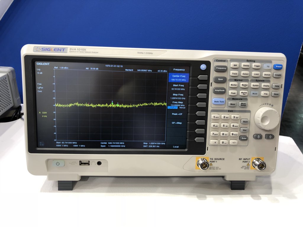
Product Demo – 1:05 – 1:20 pm ET "The new SIGLENT SVA1015X helps minimize test time by combining a swept superheterodyne spectrum analyzer
with a two port VNA. The available Distance to Fault, EMI,
and complex impedance measurement options..."
"...improved UI with new touch screen, mouse, and keyboard support."
Estimated release May 2018
Estimated price around 1500$
Spectrum 9kHz - 1.5GHz and with TG
DANL -160dBm/Hz
Standard including preamplifier
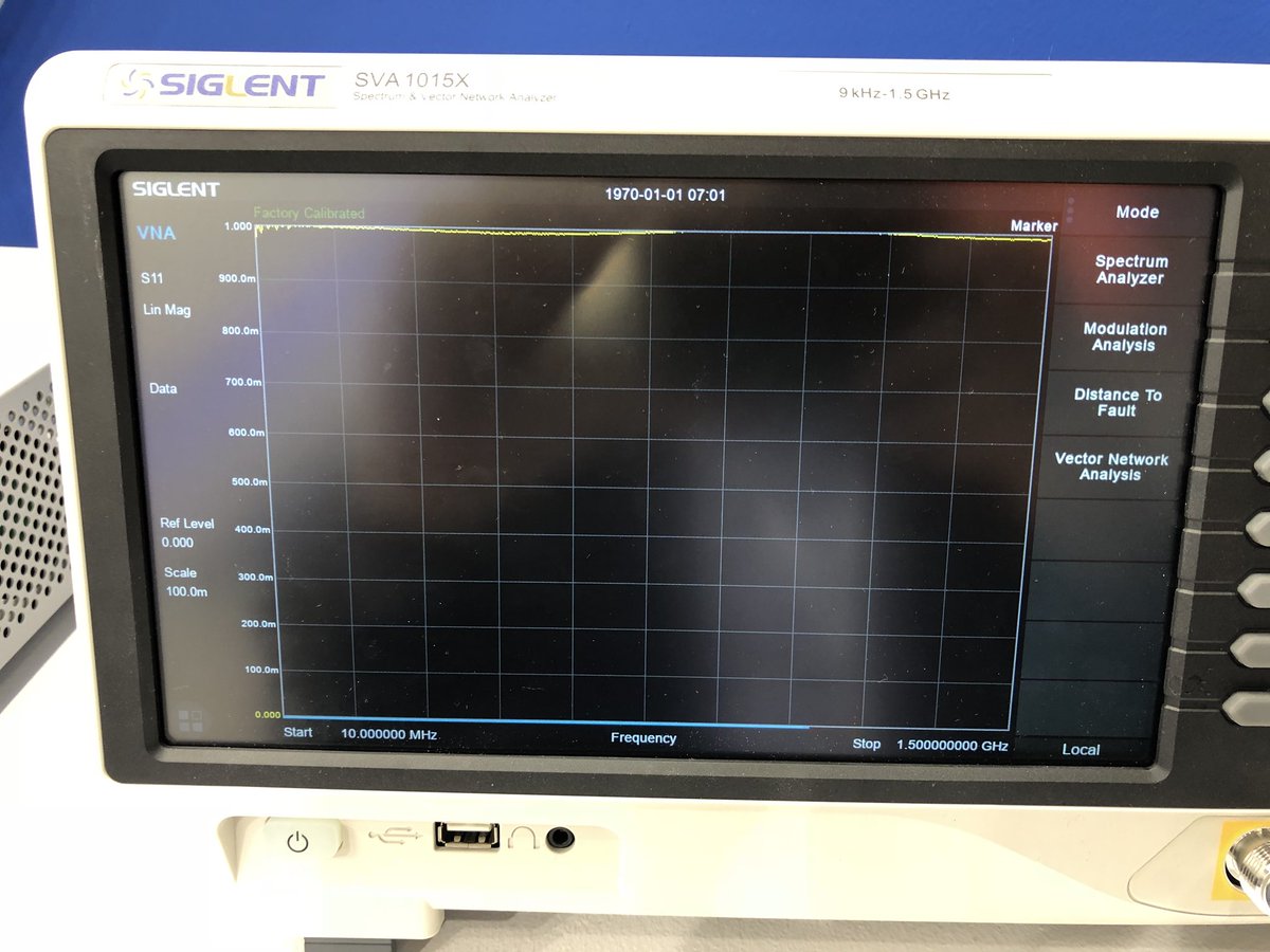
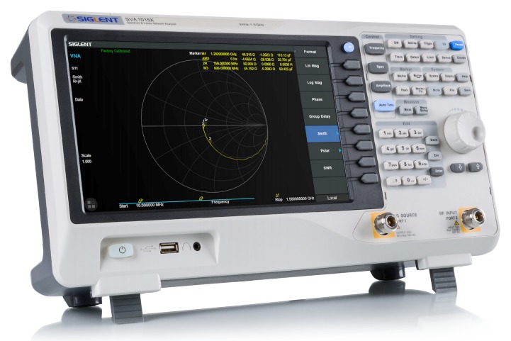
Vector Network Analyzer
Cable Test
Antenna Test
Display 10.1" 1024x600 capacitive touch panel.
Support also ext Keyboard and Mouse
And more.... soon.
reserved (SVA1032X bit better level accuracy and tiny bit better min. DANL)
1.5Ghz seems rather low for a VNA these days.
Is there a 3.2 and or 6Ghz version as well?
3 and 6Ghz are probably not in the price segment they’re aiming this thing at. And there are tons of antennas in subgiga to use this one for I guess.
Why that picture is blurred except for the brand name though heh....not like you can see the specs by just looking at it. (Seems the picture was posted on Twitter, withou blurr)
Now this is interesting!
I was wondering how long it would take.
As a miniVNA Tiny user I am really curious. I know it has lots of limitations, but the price is unbeatable so far.
Although I imagine the price of this thing will be in the €/$1000 - €/$2000...
I guess market for lower end VNAs is not very big? If something like this would be priced so that its attractive to "average" Amateur Radio hobbyist, Siglent probably would sell orders of magnitude more....
Well, price-wise, these are cerainly not for me, but maybe HP-8753s are getting cheaper, then


I guess market for lower end VNAs is not very big? If something like this would be priced so that its attractive to "average" Amateur Radio hobbyist, Siglent probably would sell orders of magnitude more....
For the typical antenna adjustments the cheap VNAs are enough. I have a miniVNA Tiny and it works really well. If you are doing finer stuff like filters it’s a different matter of course.
What will be its dynamic range?
I would say similar to SSA3000X
btw the SVA has a 10.1" touch screen display
Wow, it looks very modern for a thing made in 1970 , or is it a bug in the firmware
Wow, it looks very modern for a thing made in 1970 , or is it a bug in the firmware
1.1.1970 is UNIX "epoch time" - (and its little cousin linusnix).
We also remember this old method for modify SSA3000X using this "epoch time" trick.
Looking at the port labels I am guessing that it will need an external coupler for S11 measurements...?
Looking at the port labels I am guessing that it will need an external coupler for S11 measurements...?
Ouch, hopefully the labeling is just incorrect, otherwise it is awful lame and better be crazy cheap. Pretty hard to call it a two port analyzer.
Looking at the port labels I am guessing that it will need an external coupler for S11 measurements...?
Apparently the Chinese know a way to do it without one. But my bet is they have no idea how to do it at all.
Looking at the port labels I am guessing that it will need an external coupler for S11 measurements...?
Apparently the Chinese know a way to do it without one. But my bet is they have no idea how to do it at all.
Looking at the port labels I am guessing that it will need an external coupler for S11 measurements...?
Ouch, hopefully the labeling is just incorrect, otherwise it is awful lame and better be crazy cheap. Pretty hard to call it a two port analyzer.
Actually it isn't really a bad decision for a combo device, as you can buy what you need. Also they already have a coupler for the SA range.
But _if_ it is the case there will be quite a bit of port swapping needed.
Looking at the port labels I am guessing that it will need an external coupler for S11 measurements...?
Apparently the Chinese know a way to do it without one. But my bet is they have no idea how to do it at all.
You don't need a system that uses an external coupler to measure S11. The DG8SAQ VNWA is a two port vector network analyzer that will measure S11 up to 1.3GHz and it uses a resistive bridge internally.
The difficult part is the phase of S11 (or indeed of any S-parameter they are measuring) - how do they compare the phase of the reflected signal with that of their source signal?
Yes, I meant coupler or bridge.
It can also be done with a circulator or even a splitter. Circulators are normally not wide band, but there is a older solid state design that Charles Wenzel has published for low frequencies and low power. It would be interesting to see how high in frequency that could operate using the fastest op-amps available now.
The phase comparison part is not difficult. Internally there would be a second, reference, detector which is fed with a portion of the TG signal. The detectors are just mixers and ADC's. The some maths in the FPGA and bobs your uncle.
It probably has only two receiver channels internally instead of three or four. They may have a single directional coupler (more likely a resistive bridge) on the main port to support S11 measurements, and a conventional non-directional ALC sampler on the TG port. S21 measurements would be scalar only, implemented by treating the tracking generator output as a transmit-only "port 2."
Not necessarily a bad way to go, at the right price. But it limits your calibration options. It had better be cheap... very cheap.
You don't need 4 or two receivers to measure S21 - one is enough, and also phase can easily be measured with just one receiver if you compare the received phase to the phase at the TG output.
Implement a switching matrix (e.g. four RF SPDT switches) to change the DUT direction and then just have another switch path to select for reflection and transmission + the math.
Very crude compared to modern stuff but sure it works.
You don't need 4 or two receivers to measure S21 - one is enough, and also phase can easily be measured with just one receiver if you compare the received phase to the phase at the TG output.
That is assuming the DUT doesn't affect the phase and amplitude of the TG. AFAIK most DUTs will affect the amplitude and phase of the TG so you'll need to measure the TG output while it is loaded by the DUT.
Could you elaborate how you think the phase is being affected and how is this relevant if you are comparing the phase at the input to the output?
It’s a relative measurement after all.
I have few more images about it which show the different mode. The unit was not connected to a signal or component. Would you like me to post them?