Hi there. Sorry for this basic question. I'm taking the power board out of an old OG Xbox and installing it in a separate enclosure so I can use it for testing Xbox motherboards. I will be providing a switch on the front panel of the enclosure to connect the 240 V AC mains power. What I'd like to do is wire in an indicator light that turns on when the device is powered. But I'm not sure how to go about that. What I'd like is a component I can wire in series with the power switch which will just work. But maybe that's not the way to go about this? I'm not sure. What sort of power-on indicator should I buy and how should I connect it to the internal wiring and the power switch? Thanks in advance.
I will be providing a switch
use an illuminated switch,1 less hole to make,and if its double pole simple to wire
I will be providing a switch
use an illuminated switch,1 less hole to make,and if its double pole simple to wire
Thanks for the suggestion. Would one of
these work?
I'd still like an answer to my original question so I can learn how it might work.
But I'm not sure how to go about that. What I'd like is a component I can wire in series with the power switch which will just work. But maybe that's not the way to go about this? I'm not sure. What sort of power-on indicator should I buy and how should I connect it to the internal wiring and the power switch? Thanks in advance.
You do not want to wire this in series. You want to wire the light in parallel with the load (console). Otherwise the voltage going to the console will be lower than 220V (due to the drop across the bulb).
This will tell you that 220V is present, but it will not tell you how much current the console is pulling. For that you will need a current clampmeter. This might be a useful diagnostic tool to have anyway (if you're repairing lots of consoles).
Just remember you’re playing with mains.
Around a second of adequate contact with your skin might render the LED unnecessary.
Just remember you’re playing with mains.
How could I forget? I have to say I'm very nervous about this project. I watched the following video and the presenter seemed very cavalier about playing with mains power.
So I've been doing some research and I've come up with the following schematic (based on the info from the YouTube video I referenced above) but I'm not sure what value to use for R1? That's just there to bleed out C1, so maybe 100K?
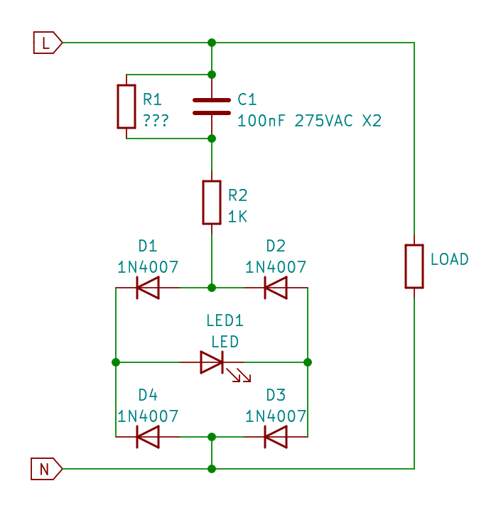
A bridge rectifier is overkill ... a single diode is enough. It will do half wave rectification and that's enough for a basic led... worst case scenario if you see some flickering, you can just add a small capacitor to smooth the voltage.
If you want, add a zener diode, which will cap the voltage to reasonable levels.
See for example this application note about such power supplies :
https://ww1.microchip.com/downloads/en/AppNotes/00954A.pdfYou have right at the start a capacitive dropper circuit and at page 10 there's one with extra safety considerations.
I discovered the W10G bridge rectifier, so figure I will use one of those. Not sure what value to use for R1 though?
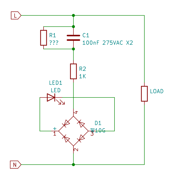
Some high value , 470k-1meg
again, you don't need a bridge rectifier, a single diode is enough. but you do what you want.
Won't a capacitive dropper fail to work if you only have one diode?
I noticed that the O.P. has already started a new thread asking about a suitable AC voltage dropping capacitor, but I have a suggestion of my own. Perhaps it's too late, though.
I noticed that Jaycar have a transformer (MM-2002) with multiple output taps (6.3V, 7.5V, 8.5V and others) which could be used to directly drive a red LED (Vf =1.8V) or a pair of anti-parallel red LEDs. Using the 6.3V and 7.5V taps, it's possible to get 1.2V - 1.3V (RMS) which equates to approximately 1.8V peak across the red LED. There's no need for a current limiting resistor since the DC winding resistance between the secondary taps is probably enough. I should mention that the transformer is rated at 15VA which is obviously excessive for driving the LED, but the voltage taps are suitable, though.
Alternatively, it might be possible to use an NCP785A "wide input voltage range linear regulator" to output 3.3VDC to drive an LED up to a few mA. A current limiting resistor would be required to be connected between the output of the linear regulator and the LED.
Link to the Jaycar transformer:
https://www.jaycar.com.au/6-3-15v-15va-1a-multi-tapped-type-2155/p/MM2002Link to the NCP785A datasheet:
https://www.onsemi.com/pdf/datasheet/ncp785a-d.pdfThere's also an EEVBlog discussion thread:
https://www.eevblog.com/forum/blog/eevblog-1285-how-to-do-design-by-inspection
A bridge rectifier is overkill ... a single diode is enough. It will do half wave rectification and that's enough for a basic led... worst case scenario if you see some flickering, you can just add a small capacitor to smooth the voltage.
If you want, add a zener diode, which will cap the voltage to reasonable levels.
See for example this application note about such power supplies : https://ww1.microchip.com/downloads/en/AppNotes/00954A.pdf
You have right at the start a capacitive dropper circuit and at page 10 there's one with extra safety considerations.
There are some pretty small surface mount bridge rectifiers. It might actually work out smaller, than using a single diode and capacitor.
https://docs.rs-online.com/c927/0900766b814bbf0c.pdf
Why are you putting the indicator light on the mains side? I would put it on the LV side of the PS. Then you just need a resistor and an LED.
I would simply buy an indicator light that has the correct rated voltage in this case I guess it's 240VAC?