-
I wonder, if you do the mod described, if you would get an error for missing components.
As it's just output control, filtering etc. I doubt it would know.
Sent from my SM-G935V using Tapatalk
But there will certainly be an option resistor somewhere to let the software know.
RossS - any chance you could dump the startup messages to see what the ID values are ?
-
Of course instead of adding the parts to the main PCB, a more warranty-friendly option would be to just take the signals off onto a piggyback PCB with all the parts on
-
I'm impressed.
But i admit that i would not modify any Keysight-Scope in the warranty-time.
After that ... maybe
-
Does someone have an image of the AWG section from a NON-AWG version?
I bought the 70MHz version without AWG (DSOX1102A). Here are pics of the main board.
Thanks
So they only fit the parts needed for the demo output. Same PCB as expected. -
Is the PSU the same ?
Here's the power supply. Looks the same to me as the one in Dave's teardown. I'm happy to take other pictures of the scope if anyone would find them useful.
70MHz No Gen
100MHz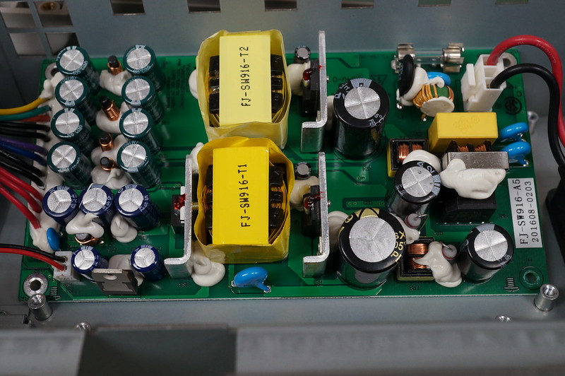 Keysight 1000 X-Series Oscilloscope Teardown by Dave Jones, on Flickr
-
Is the whole batch of those black-and-gold-marking caps on the primary, ever so slightly bulged? The one in the teardown video definitely was (as confirmed by Dave himself, in the comments)

Not like i'd trust Aishi / Asia-X / Xunda / OKCAP ( ) in any of my gear anyway...
The only two missing are CapXon and Fuhjyyu
That being said, "of course" it's the same 5-10$ power supply - would you really expect them to spec different models for the with / without wavegen models?
Economies of scale
-
Quote
RossS - any chance you could dump the startup messages to see what the ID values are ?
Sure, no harm in holding a probe up to the right via. Looks like the dump is the same as Dave's, except I've got BLT Product Config 23 instead of his 24.
My DSOX1102A:Code: [Select]BLT Product Config 23
Bandwidth : 200MHz
#Channel : 2
Board Rev : FPR
Clk Gating : Baldwin
Sample Rate : 4GSa
LAN PHY : No
BLT Module Config 02
Rev : LP3
Sample Rate : 5GSa/s
=========================================
BLT_PRODUCT_CONFIG_0, 0.985v, ID3
BLT_PRODUCT_CONFIG_1, 0.692v, ID2
BLT_MODULE_CONFIG_0, 0.687v, ID2
BLT_MODULE_CONFIG_1, 0.010v, ID0
Dave's DSOX1102G (https://www.eevblog.com/forum/blog/eevblog-978-keysight-1000x-hacking/msg1154965/#msg1154965):Code: [Select]BLT Product Config 24
Bandwidth : 200MHz
#Channel : 2
Board Rev : FPR
Clk Gating : Baldwin
Sample Rate : 4GSa
LAN PHY : No
BLT Module Config 02
Rev : LP3
Sample Rate : 5GSa/s
=========================================
BLT_PRODUCT_CONFIG_0, 1.251v, ID4
BLT_PRODUCT_CONFIG_1, 0.692v, ID2
BLT_MODULE_CONFIG_0, 0.687v, ID2
BLT_MODULE_CONFIG_1, 0.005v, ID0
Full dump from my DSOX1102A:Code: [Select]
U-Boot 2010.03 (Oct 18 2011 - 14:28:06)Agilent P500
CPU: SPEAr600
DRAM: 128 MiB
Flash: 512 KiB
NAND: internal ecc 128 MiB
Debug serial initialized ........OK
RTC: 2024-17-3 7:102:37.47 UTC
Microsoft Windows CE Bootloader Common Library Version 1.4 Built May 7 2015 01:38:03
Microsoft Windows CE 6.0 Ethernet Bootloader for the Agilent P500 board
Adaptation performed by Agilent Technologies (c) 2008
PHY not found.
System ready!
Preparing for download...
RTC: 2024-17-3 7:102:37.47 UTC
Loading image 1 from memory at 0xD0600000
O
BL_IMAGE_TYPE_BIN
X
XXXXOOOOXXOOOOOOOOXOXOOOOOOOOXOOOXOOOOXXOOOOOOOOOXOOOOXOXXOXOXXOXOXOXOXXXXOOXXXOOOOOOXXOXXOXXXXXXOOOXXXOXXOOOXXXOXXOOOOXOOXXOOOXOOOOXOXOOOOOXOOOXOOXOXXOXOXXXXXXOXXXXOOOXOOOXOXOOOOXOOOOXOXOXOOOOOOXX
OOOXOOXOOOOXOOOOXOOXXOOXOOOOOOOOOXOOOOXOOOOOOXOXOOOOXOXOOOOOOOXXOOXOOXOXOOOXOOOXOOXXOXOXOOOXOXXXXXOXOXXXOXXXXOXOXXOOOXXXXOXXXXOXXXXXXXOXXXXXXOXXOXXOXXOOXXOXXXOXXXXOOOXXX
OOOXXXOXXOOXOOOOOOOOOOOOOOOOOOOOOOOOOOOOOOOOOOOOOOOOOOOOOOOOOOOOOOOOOOOOOOOOOOOOOOOOOOOOOOOOOOOOOOXXOOOOOOOOOOOOOOOOOOOOOOOOOOOOOOOOOOOOOOOOOOOOOOOOOOOOOOXXXXXOOOXOXOOXOOXXXXXXXXXXXXXrom_offset=0x0.
XXImageStart = 0x80361000, ImageLength = 0x1A80C40, LaunchAddr = 0x80362000
Completed file(s):
-------------------------------------------------------------------------------
[0]: Address=0x80361000 Length=0x1A80C40 Name="" Target=RAM
Loading image 1 succeeded.
ROMHDR at Address 80361044h
Preparing launch...
RTC: 2024-17-3 7:102:37.50 UTC
Launching windows CE image by jumping at address 0x 362000
Windows CE Kernel for ARM (Thumb Enabled) Built on Mar 8 2013 at 17:05:33
Setting up for a Cold Reboot
Done Setting up for a Cold Reboot
Windows CE Firmware Init
BSP 1.0.0 for the SPEARHEAD600AB board (built Sep 28 2016)
Adaptation performed by ADENEO (c) 2005
+OALIntrInit
-OALIntrInit(rc = 1)
Initialize driver globals Zeros area...
pDrvGlobalArea 0xa0060000 size 0x800 (0xa0060800 -0xa0060000)
Initialize driver globals Zeros area...done
OALKitlStart
Firmware Init Done.
OALIoctlHalEnterI2cCriticalSection init i2c cs
++SER_Init: context Drivers\Active\14
SER_Init, dwIndex:2
SER2 got sysintr:0x00000017
SER2 Serial Port, new baud rate:0x1c200 (UARTCLK:48000000 IBRD:0x1a FBRD:0x2)
OHCI\system.c, GCFG_USBH1_SW_RST
OHCI\system.c, GCFG_USBH2_SW_RST
LAN PHY NOT detected.
DeleteP500EnetRegistry:
\Comm\GMAC 0x0
\Comm\GMAC1 0x0
\Comm\Tcpip\Linkage 0x0
\Drivers\Virtual 0x0
\Drivers\BuiltIn\LIN 0x5
LIN: Data Valid
BALDWIN_DDI: cBaldwinHwIf::Init: Initializing...
BALDWIN_DDI: cBaldwinHwIf::Init: Scope successfully identified.
BALDWIN_DDI: cBaldwinHwIf::Init: Success!
Device load time:
NANDFLASH: 1 ms
SNANDFLASH: 1 ms
SHIM DLL, LoadRealDll [PalIO.dll] for [AgilentPalIO.dll]
SHIM [AgilentPalIO.dll] Get Process Addresses
LaunchInfiniiVision:
=========================================
BLT Product Config 23
   Bandwidth   : 200MHz
   #Channel    : 2
   Board Rev   : FPR
   Clk Gating  : Baldwin
   Sample Rate : 4GSa
   LAN PHY     : No
BLT Module Config 02
   Rev         : LP3
   Sample Rate : 5GSa/s
=========================================
BLT_PRODUCT_CONFIG_0, 0.985v, ID3
BLT_PRODUCT_CONFIG_1, 0.692v, ID2
BLT_MODULE_CONFIG_0, 0.687v, ID2
BLT_MODULE_CONFIG_1, 0.010v, ID0
CANINE_BOARD_REV, 0.002v, ID0
CANINE_MODEL_NAME: MARSUPIAL, 1.740v, ID6, MARSUPIAL
CANINE_EXTMODULE, 2.488v, ID8, SWID8
CANINE_MSO_REV, 0.630v, ID2, SWID2
SHIM DLL, LoadRealDll [PalSStorage.dll] for [AgilentPalSStorage.dll]
SHIM [AgilentPalSStorage.dll] Get Process Addresses
Released build, Sep 28 2016, 00:17:51
Initializing FPGA...
************************************
FPGA Type: Marsupial
Ver: 1.067 Released
Build Time: Tue Jun 14 17:13:42 2016
Build Machine: 2UA5461ZWH
************************************
cMarsupialCalMgr::cMarsupialUserCalFactors::cMarsupialUserCalFactors size 146412
cMarsupialCalMgr::cMarsupialServiceCalFactors::cMarsupialServiceCalFactors size 704
cMarsupialCalMgr::cMarsupialFactoryCalFactors::cMarsupialFactoryCalFactors size 896
Calibration mode User
Recall \Secure\cal\FactoryCal2.dat - ok
Recall \Secure\cal\ServiceCal1.dat - ok
Recall \Secure\cal\UserCal8.dat - ok
Cal Date Wed Dec 14 11:24:30 2016
will do USB phy workaround: CheckCRC
Startup sequence is complete.
System has been running 14.642057 seconds
Start Up Sequence 5.924234
Memory Load 48%
System Physical Memory 34.906 / 73.465 MB
Process Virtual Memory 44.500 / 1024.000 MB
-----> InfiniiVision is running <----- -
Is the whole batch of those black-and-gold-marking caps on the primary, ever so slightly bulged? The one in the teardown video definitely was (as confirmed by Dave himself, in the comments)
The one on my scope definitely is as well.
-
Is the whole batch of those black-and-gold-marking caps on the primary, ever so slightly bulged? The one in the teardown video definitely was (as confirmed by Dave himself, in the comments)
The one on my scope definitely is as well.
Pre-bulged caps? Maybe they do some sort of burn-in on the power supply boards before installation.
Weed out the really bad ones.
-
@RossS
You probably don't want to hack into your new scope, but I see that your BLT_PRODUCT_CONFIG_0, 0.985v, ID3 while Dave's (G) version is ID4 (1.25V). Would the wavegen appear as enabled/present on yours if you changed that ID I wonder? -
That is precisely what I was thinking. If you could enable it, buy or roll your own front end
Sent from my SM-G935V using Tapatalk
-
Wonder what the portion of the dumps with X and O is for? If binary, why not just use ASCII?
Sent from my SM-G935V using Tapatalk
-
For what it's worth, I was able to interrupt the boot process by sending a space over UART1 immediately after power on:Code: [Select]
P500 Boot Loader Configuration :

Mac address .......... (00:03:D3:04:10:00)
Ip address ........... (192.168.1.100)
Subnet Mask address .. (255.255.255.0)
DHCP ................. (Enabled)
Boot delay (seconds).. (0)
Load image 1 at startup

Image addresses. (0xdxxxxxxx for NAND, 0x8xxxxxxx for RAM)
        1 (0xd0600000)
        2 (0xd1e00000)

1) Load memory resident image 1 now
2) Load memory resident image 2 now
3) Load memory resident image 3 now
d) Download from platform builder now
u) Start u-boot by resetting
v) Verify Images
>
Image 1 is what's loaded by default. I'm curious to know what image 2 is (maybe a factory reset / backup image?), though I didn't want to try booting from it.
I also buzzed out the UART2 pins and found them routed to one of the main board connectors, but the traces appear to stop at that point. I tried connecting to it, but nothing is transmitted (confirmed on a scope that TX just stays high after power on), and nothing I sent at 115.2k baud seemed to do anything. Oh well.
-
@RossS
You probably don't want to hack into your new scope, but I see that your BLT_PRODUCT_CONFIG_0, 0.985v, ID3 while Dave's (G) version is ID4 (1.25V). Would the wavegen appear as enabled/present on yours if you changed that ID I wonder?
Ok, why not. :p I changed that config resistor to match Dave's G version scope, and now I get the same product config as he had (ID4, and overall config 24).
It looks like that enabled the wavegen license (see picture), but then I realized the front bezel has no wavegen button, so I couldn't easily continue poking. You'd have to hack that in too along with the output bnc and all the other missing components. Seems like a lot of effort at this point to get free (well, parts cost only) wavegen.
-
Hacking in a membrane button and adding all the components might not be worth it, but you could try to verify that the wavegen functionality is present by improvising a button while powering the scope without the front panel? Any conductive material over the pads should do it.
-
Hacking in a membrane button and adding all the components might not be worth it, but you could try to verify that the wavegen functionality is present by improvising a button while powering the scope without the front panel? Any conductive material over the pads should do it.
I think it's fairly clear the functionality is there. As more evidence, I can select wavegen as a trigger source now where it previously wasn't an option. I'm not personally interested in the wavegen support and it's a bit of a pain to get access to the front of the keyboard pcb, so I'd rather hold off on further tests for now. -
You can plug in a USB keyboard for text entry. I wonder if there are key aliases for the front-panel buttons.
-
Anyone tried to hook the scope up to a PC and control it with BenchVue? .. never mind, the 1000X series is not on the support list http://www.keysight.com/main/editorial.jspx?cc=NO&lc=eng&ckey=2418722&nid=-32133.0.08&id=2418722
Do Keysight not plan to support this for 1000X series? -
Anyone tried to hook the scope up to a PC and control it with BenchVue? .. never mind, the 1000X series is not on the support list http://www.keysight.com/main/editorial.jspx?cc=NO&lc=eng&ckey=2418722&nid=-32133.0.08&id=2418722
I'm sure they will, but probably not top priority at the moment.
Do Keysight not plan to support this for 1000X series? -
You can plug in a USB keyboard for text entry. I wonder if there are key aliases for the front-panel buttons.
Any luck with a USB to network adapter? I've been pondering if they happened to support one since it first came out. If it does support one I imagine it may be one specific model though. -
Hi,
I am just wondering what the current state of the hack is?
I believe:
1) The bandwidth can be increased by changing the ID resistors.
2) The max sampling rate can be changed also with the ID resistors.
3) The memory depth can be changed
4) The Wavegen can be turned on in the software, but this is not so useful, because a significant piece of circuitry is missing from the main board. Mikeselectricstuff suggested that this could be addressed with an add in board to replace the missing parts. But if you do this you are left with the missing button on the front panel.
So this suggests that if you want the Wavegen you need to buy the minimum configuration with the Wavegen hardware installed.
At this time the Embedded serial triggering and analysis for I²C, SPI, UART/RS-232 (DSOX1EMBD), for I²C, UART/RS-232 (EDUX1EMBD) has not been hacked?
This might be the most useful hack.
Did I get it right?I think that's correct, though I've not yet seen specific info on resistor values to get the "optimum" functionality - bit of a major omission from Dave's video.
The main thing we don't know is what features (if any) are disabled by license in the EDUX version, and if any of the links are equivalent to the 70->100MHz upgrade.
I am tempted to buy one of the DSOX 1000 scope just to get the Bode plot function. I do a lot of work with power supply control loops so the FRA would really useful. It is cheaper to buy a DSOX-1000 scope than but the software option for a DSOX-3000T scope. But the limited (coarse) granularity of the FRA is a show stopper at the moment.
Regards,
Jay_Diddy_B
-
Well, even so, "just" with the already-confirmed(?) hacks, you can turn a 600$-ish 50MHz educational-wavegen one into a 1000$-ish >200MHz fully-fledged one... Which isn't too shabby in itself, imho.
Well, that is, assuming the issue Mike pointed out in his video from today, gets taken care of in the near future, of course
I'm getting very tempted
PS: What're the odds this has the same front-end as the DSOX2000 series? That might sort of explain the >200MHz capability, methinks... -
I think that's correct, though I've not yet seen specific info on resistor values to get the "optimum" functionality - bit of a major omission from Dave's video.
The main thing we don't know is what features (if any) are disabled by license in the EDUX version, and if any of the links are equivalent to the 70->100MHz upgrade.
-
Not the one I tried. As AFAIK there is no "generic" USB-ethernet adapter, it would have to be something that is explicitly supported by the build of WinCE, and would also need to be supported by the Keysight application.You can plug in a USB keyboard for text entry. I wonder if there are key aliases for the front-panel buttons.
Any luck with a USB to network adapter? I've been pondering if they happened to support one since it first came out. If it does support one I imagine it may be one specific model though.
Seems unlikely, and not hugely useful. The only thing I've ever used network connectivity for on any scope is pulling screen images without having to plug in a USB stick
It does have SCPI support over USB, so that would cover a lot of use cases.
-
Hacking in a membrane button and adding all the components might not be worth it, but you could try to verify that the wavegen functionality is present by improvising a button while powering the scope without the front panel? Any conductive material over the pads should do it.
I think it's fairly clear the functionality is there. As more evidence, I can select wavegen as a trigger source now where it previously wasn't an option. I'm not personally interested in the wavegen support and it's a bit of a pain to get access to the front of the keyboard pcb, so I'd rather hold off on further tests for now.
It is really academic, because such a large part of the hardware is missing, but can you access the FRA or the Bode function?
Thanks,
Jay_Diddy_B_G ( I was hacked !!)