-
To see the much clearer schematics by Oldway, I had to click on the image, then right-click on the image and select VIEW IMAGE. Finally. click again to magnify the png image to its full size. They are very sharp now... thanks.
-
You could also download the PNG pictures and open them on your computer.
They seems to be very good. -
Does anyone have gerber files or know how to make the pics for thermal transfer
 ?
?
-
Hi TorqueRanger and the group,
I have attached pdfs that should help DIY construction of the ESR meter adapter.
There is copper layer which has been mirrored for toner transfer. I have included a scale so that you can make sure the board is the correct size.
There is pdf showing the silk screen layer so you know where the components go.
I have also attached the latest version of the schematic.
Jay_Diddy_B
Thank you so very much
Thanks Again
Jason SR -
Does anyone have any reviews ,updates ,or problems ??
-
Does anyone have any reviews ,updates ,or problems ??
I was sent one of these by Jay, and I haven't had the time yet for a full review, but I'll tell you what I think so far. 1st. I received a dud. I found that there was a dry joint on a 7805 regulator, fixed that, and went on my way. It is really very easy to use, outputting 100mV per ohm, and plugging directly into the DMM. I have tested it, and it is relatively accurate. I have used it in helping me to determine replacements caps in my ageing 6114A power supply, and can say that 4 wire kelvin measurements really do help. All in all, a nicely designed little adapter that does what it's supposed to without fuss. Only tip is to test each one .
.
-
No problem ...Does anyone have any reviews ,updates ,or problems ??
I was sent one of these by Jay, and I haven't had the time yet for a full review, but I'll tell you what I think so far. 1st. I received a dud. I found that there was a dry joint on a 7805 regulator, fixed that, and went on my way. It is really very easy to use, outputting 100mV per ohm, and plugging directly into the DMM. I have tested it, and it is relatively accurate. I have used it in helping me to determine replacements caps in my ageing 6114A power supply, and can say that 4 wire kelvin measurements really do help. All in all, a nicely designed little adapter that does what it's supposed to without fuss. Only tip is to test each one.
Thanks for the information because I was going to etch a board up and see how it works out too.. -
Sorry for the delay, but for anyone interested, I have made a short video detailing how it works and a demonstration of usage.
-
Is there any chance that you modify schematic so that we can use it with analog meter 100uA. If so please make the scale non linear, the range of up to 50ohm and that 25% of the scale goes for the range from 0-1ohm and the rest is for up to 50ohm.
I know that most of engineers does not consider analog ESR meter, however, for troubleshooting work it is way faster and better to use than digital.
With this modification we would have final ESR tester that everybody can use and be happy.
The ideal would be to implement both, digital and analog readout at the same time -
If you can do this I will create scale for the meter so that everybody can use.
-
Is there any chance that you modify schematic so that we can use it with analog meter 100uA. If so please make the scale non linear, the range of up to 50ohm and that 25% of the scale goes for the range from 0-1ohm and the rest is for up to 50ohm.
I know that most of engineers does not consider analog ESR meter, however, for troubleshooting work it is way faster and better to use than digital.
With this modification we would have final ESR tester that everybody can use and be happy.
The ideal would be to implement both, digital and analog readout at the same time
Zaoka:
If you are looking for an analog meter, have a look at this project:
https://www.eevblog.com/forum/projects/5-transistor-esr-meter-design/msg171364/#msg171364
This one does not have the protection that the ESR Meter Adapter has.
Jaxbird designed a digital version of the 5 transistor circuit, He linearized the output using a micro. You can find information in this thread:
https://www.eevblog.com/forum/projects/esr-meter-build/
You could probably build a dual display version.
Jay_Diddy_B
-
I encounter this design back in 2011, not sure where from, but its basically the same as discussed here.
It defaults to the 4W measurement mode.
-
I encounter this design back in 2011, not sure where from, but its basically the same as discussed here.
It defaults to the 4W measurement mode.
That design was posted in Silicon Chip magazine by Len Cox.
Similar maybe, but there is a tiny yet crucial difference, it has no protection against a charged cap compared to Jay's design, cmiiw. -
I encounter this design back in 2011, not sure where from, but its basically the same as discussed here.
It defaults to the 4W measurement mode.
The design is similar in functionality, and probably has similar performance. As BravoV said, I have implemented better protection for charged capacitors and applied voltage.
The Silicon Chip Design has four chips plus a regulator.
My design uses only two chips plus a regulator. The reduced chip count allows the circuit to be built on the back of the lid.
Jay_Diddy_B
-
If Jay_Diddy_B did know the Silicon Chip Design of 2011, it would be fine if he had presented his project as an improvement of this earlier design.
But, anyway, this new version has a lot of features:
- using +/- 2.5V power supply instead of +/-5V, so it can be powered by a single 9V battery.
- fully protected against charged capacitors.
- few components
- single sided board project.
But i don't agree with some ideas:
- 4W is nonsense as this project is not a high precision tool....it's intended for diagnose and repair.
Using Kelvin probes is not practical at all.
- need a zero ajust pot for compensating both offset and resistance of the test probes. With such a zeroing pot, there is no more need of a multimeter with relative function, nor to choose a low offset op amp. You short circuits the probes and ajust the pot for 0V reading.
- I would prefer to have two frequencies: 100Khz and 10Khz as 100Khz seems a little high for big capacitors.
- Actual range is 100mV = 1R....better to have 2 ranges, also 1V = 1R for easier reading and greater accuracy.
- in my opinion, should use only very easy to buy components...TLC555 (cmos version of 555), 4013, 4066, LM324, 78L05.
I also found an error in this project: there is no ground reference for the inputs of the op amp because there is an isolating capacitor and high resistance values. Inputs are "floating" and are not symetricals compared with ground.
For solving this problem, I added two 10K resistors in parallel with the capacitors C3 and C4 of Jay_Diddy_B schematic.
- A made 2 new versions, the first is allready working very well. I have still to make the board of the second one, but it's not that easy because I want to make a single side board project.
-
If Jay_Diddy_B did know the Silicon Chip Design of 2011, it would be fine if he had presented his project as an improvement of this earlier design.
But, anyway, this new version has a lot of features:
- using +/- 2.5V power supply instead of +/-5V, so it can be powered by a single 9V battery.
- fully protected against charged capacitors.
- few components
- single sided board project.
But i don't agree with some ideas:
- 4W is nonsense as this project is not a high precision tool....it's intended for diagnose and repair.
etc.
Oldway is correct in his observations.
The is a very good collection of ESR meter designs, that have been collected by Kripton2035, here:
http://kripton2035.free.fr/esr-repository.html
I studied a lot of them. I made LTspice models for the analog portions of some of them.
I was aware of the Silicon chip design of 2011. I believe that it dates back to 2005.
I was also aware of the Elektor 2002 design. This is the earliest design that aware of that use analog switches instead of diodes.
The general design, is (incorrectly?) called a lock-in amplifier.
These circuits use either the 4016 or 4066 analog switches.
At some point I simulated the Silicon Chip Design:
I believe that mine circuit is the first one to use the 74HCT4053, for the analog switches. This removes the need for complementary drive signals.
I also took inspiration from the 1967 HP 4338A milliohm meter design:
(There is a d.c. path to ground for the capacitors C3 and C4. The path is through the analog switches)
I appreciate the changes that Oldway has made, and the reasons that he made them.
Jay_Diddy_B
-
That's the right way to develop a new design

Looking for what already has be done, choosing the best solutions and improving them...
Again, thanks very much for sharing your work.
Few people are doing this on this forum.Quote(There is a d.c. path to ground for the capacitors C3 and C4. The path is through the analog switches)
I don't agree, at one side, there is no resistor to ground, only 2 diodes D4 and D3, and at the other side, only a high value resistor (R11 : 1.8MR)
In the earlier design, ground reference was done by the 1K resistor and the DUT itself....in your design, this ground reference does not exist anymore because C6 is insulating this side from the grounded DUT.
-
We could use FLUKE 4W tweezers with this design if we knew where to get female terminals of this kind

http://us.flukecal.com/products/accessories/test-leads-probes-and-clips/tl2x4w-twz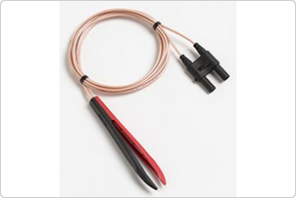
Maybe just cut it and install 2 BNC's
-
If i were a rich man...

Not a low cost solution for sure...
http://www.amazon.com/Fluke-TL2X4W-TWZ-Tweezers-Voltage-Current/dp/B00937VPPU
Only US§ 90
My solution:
http://dx.com/p/multimeter-test-leads-75cm-red-black-leads-6518
Cost: US§ 1.91 -
- A made 2 new versions, the first is allready working very well. I have still to make the board of the second one, but it's not that easy because I want to make a single side board project.
Any changes on the schematics ? Post the updated version and also share some photos once its finished, please. -
I already shared the schematics of the two versions, there is no update.- A made 2 new versions, the first is allready working very well. I have still to make the board of the second one, but it's not that easy because I want to make a single side board project.
Any changes on the schematics ? Post the updated version and also share some photos once its finished, please.
See my previous posts. (ESR3 schematic + board and ESR4 schematic)
I don't have any digital camera, nor webcam, that's the reason why I don't share photo's.
I have only a Praktica MTL3 and I have to make all the 24 poses of the film before I can have the prints...
Now you understand why my nickname is "OLDWAY"
-
Another bump, just want to thank Jay_Diddy_B for sending me the fully assembled ESR adapter kit he built, a special edition that is also hand tuned by the "Designer" himself
 , and also a very cool, one of the kind in the world, a customized 3D printed box by Jaxbird made to fit in like a glove for this ESR adapter.
Don't have enough words to explain the awesomeness when both combined, I guess I will let the photo speaks for it self.
Again, thank you very much to you both.
I don't think I need to demonstrate it's capabilities since its proven, now purely just for the killer look.
A tiny improvement at the on/off switch so I don't forget to turn it off.
-
BravoV, you are in a position to make an interesting test I have wanted to make since Jay_Diddy_B's first post in this thread.
He went to the trouble of using a phase sensitive rectifier so that his design would, as he said in post #1, "Be a true ESR meter as oppose to an impedance meter."
I'm very curious to know how well that feature works.
You have a known capacitor that can be used to test that feature. In this post:
https://www.eevblog.com/forum/projects/reference-for-lcr-or-esr-meters/msg393364/#msg393364
The capacitor you have labeled "B" is a film cap, and its impedance is very different from its ESR at 100 kHz. I didn't capture the exact sweep of the impedance/ESR for the capacitor I sent you, but I have 8 more of those caps, and here is a composite superposition of the sweeps of them:
They are quite consistent, and it's reasonable to assume that the cap I sent you has a characteristic near the ones shown. That cap is over 6 uF so it should be within the meter's operating range.
Try to make the measurement with connection made as close as possible to the capacitor body. Here are two sweeps showing the effect of making the measurement right at the capacitor body, and also with the full length leads of the capacitor:
So, if you would, what does the meter show for a measurement on this capacitor?
-
Quote
"Be a true ESR meter as oppose to an impedance meter."
That will depend on how you define a "true ESR meter". The synchronized detector is able to integrate over the two halves and subtract them, to obtain a measure (really a proxy) of the esr. However, that differential is strictly speaking non-linear, as it varies, inversely, with the voltage across the dut - which for a small capacitor can vary significantly.
We minimize that linearity with fast switching frequencies (so that the dut doesn't get charge up too much), large current limiting resistors (more like a ccs), etc. But the effect is there.
Newer commercial units generally don't use that approach: they are mostly D/FFT driven or follows 3/4 parameter 1057 algorithms.
That's not to mention the cap's own mechanism on esr - our "serial" resistor model applied to a capacitor is idealistic to begin with.QuoteI'm very curious to know how well that feature works.
Me too.