-
#175 Reply
Posted by
bitseeker
on 30 Mar, 2017 21:32
-
I had the change the routing a bit to cope with the new pin configuration. To be honest, I think it would have ultimately been easier to route with the pins the other way, but I was able to make things a bit more compact with the new footprint, so it's all good. (I don't want to squeeze things any closer than this, to allow for easy probing of parts of the circuit that don't have test points.)
Looks great!
-
#176 Reply
Posted by
timb
on 31 Mar, 2017 01:36
-
I had the change the routing a bit to cope with the new pin configuration. To be honest, I think it would have ultimately been easier to route with the pins the other way, but I was able to make things a bit more compact with the new footprint, so it's all good. (I don't want to squeeze things any closer than this, to allow for easy probing of parts of the circuit that don't have test points.)
Do not worry about this. You re-worked an existing routed section. You will not have this issue as you start routing the rest of the PCB fresh. Just rotating some of the transistors by 180 or 90 degrees in the current section would have simplified routing quite a bit, but for such a large circuit, leave it the way it is, it's perfectly fine.
Yeah, it occurred to me while reviewing the PDF after my last post that I could have simplified a couple of routes by rotating the transistors, but I'd have to tear out a bunch of other routes and move some other components, but I don't want to go down that rabbit hole.
I think that routing large boards like this requires you to be more practical than perfectionist. The layout needs to be good enough to route everything on two layers *and* be compact enough to fit everything in the limited space, however, at a certain point you just have to say it's as good as you can practically get, otherwise you'll never make any real progress.
But yeah, I'm having a good time with this.

-
#177 Reply
Posted by
BrianHG
on 31 Mar, 2017 02:49
-
Your doing perfectly fine...
-
#178 Reply
Posted by
timb
on 31 Mar, 2017 12:12
-
Tonight I got the Velocity Integrator section finished.
Here's the Velocity Integrator:
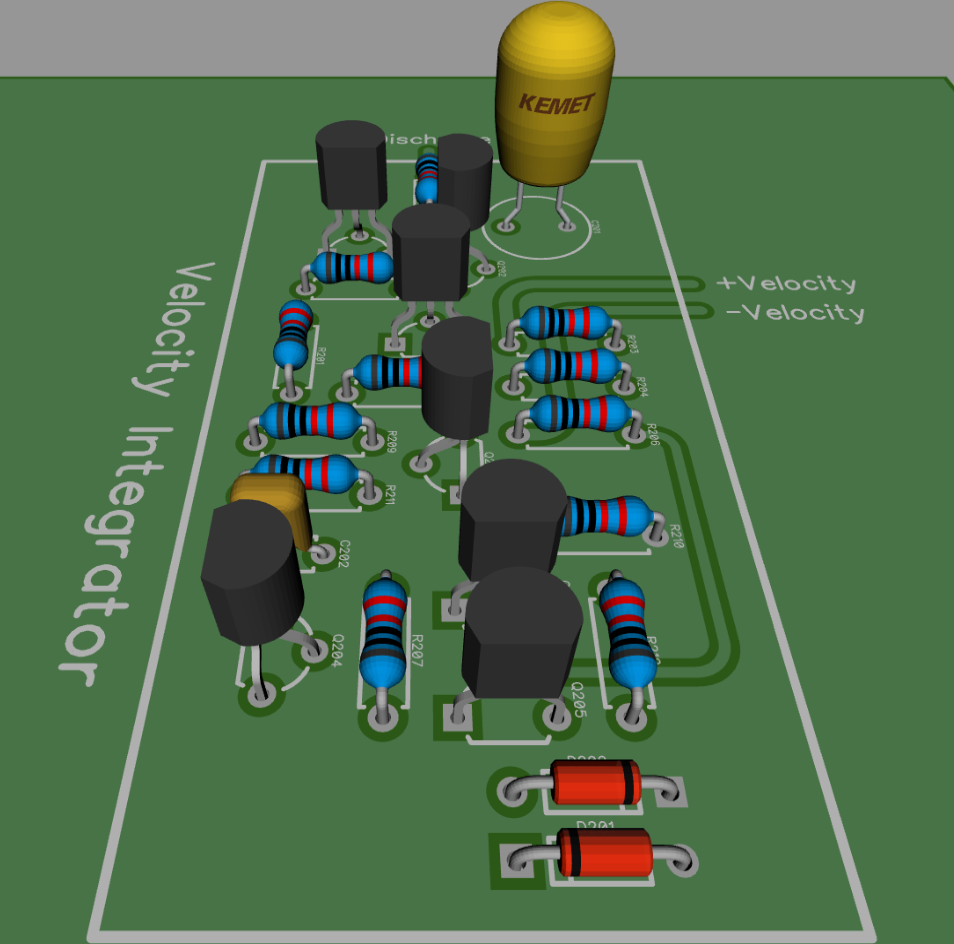
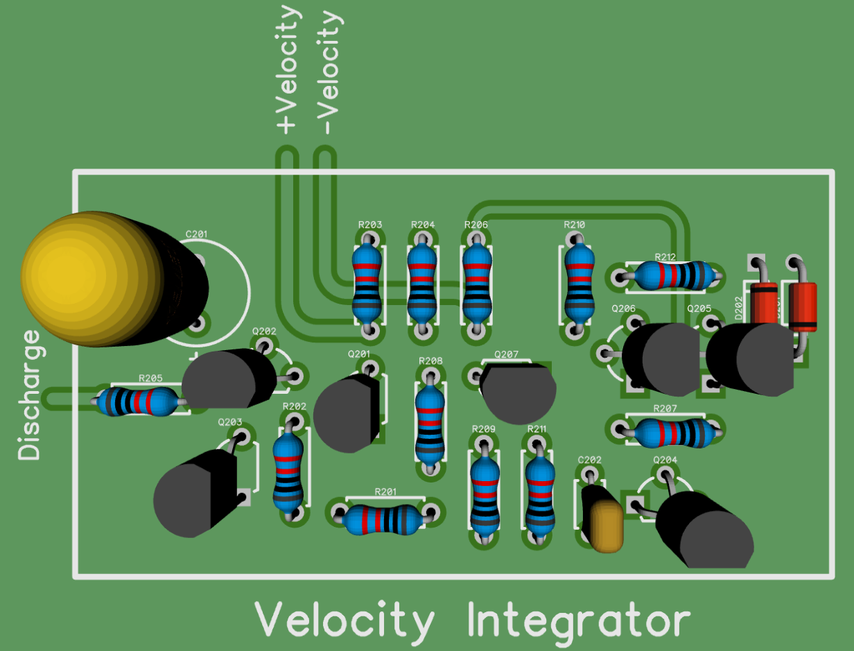
 http://timb.us/PDF/Scope_Pong_Velocity_Integrator.pdf
The Function Generator section is coming along nicely as well and I'm about 3/4 done with it. It's actually coming along quite quickly and the routing isn't bad at all. I should have at least that and another section finished tonight.
-
#179 Reply
Posted by
GK
on 31 Mar, 2017 12:37
-
Good progress, but I'd still prefer to see those two op-amp supply rail bypass caps (100nF) within the Velocity Integrator border. Ditto with the missing 100nF -15V bypass on the -REF op-amp, within the reference reg. border.
-
#180 Reply
Posted by
timb
on 31 Mar, 2017 17:31
-
Good progress, but I'd still prefer to see those two op-amp supply rail bypass caps (100nF) within the Velocity Integrator border. Ditto with the missing 100nF -15V bypass on the -REF op-amp, within the reference reg. border.
Yeah, they'll be there! All the additional bypass caps we talked about will be placed just inside each section's border where they branch off the main power buss, so once I route that I'll place them.
I already went back and fixed the -REF op-amp's missing bypass since the last screen shot of that section.
-
#181 Reply
Posted by
tautech
on 31 Mar, 2017 18:40
-
Tim, great work, if you're fussy about layouts they do take some real time.
May I ask what size annular ring size you're using and the pad hole size ?
I've had some pads lift when reworking PCB's and as a result my preference is for larger pads to minimize the chance of this.
When I can I stick with 100 mil and maybe alter the shape from round if more clearances are needed.
-
#182 Reply
Posted by
timb
on 31 Mar, 2017 20:17
-
Tim, great work, if you're fussy about layouts they do take some real time.
May I ask what size annular ring size you're using and the pad hole size ?
I've had some pads lift when reworking PCB's and as a result my preference is for larger pads to minimize the chance of this.
When I can I stick with 100 mil and maybe alter the shape from round if more clearances are needed.
In general, for hole size I'll use component lead diameter + lead tolerance + 0.05mm (to account for plating) + 0.1mm (as a safety margin). That's worked out extremely well in the past.
Minimum annular ring is twice the hole diameter. For large components I'll use much larger pads, to help anchor them down and prevent the pads from lifting from the extra heat needed durning soldering.
I'll grab some measurements of the pad sizes for the components on the board tonight and post them. I think most of them should be acceptable, though I'm not happy with the pad sizes for the diodes, I think they need to be a bit bigger.
-
-
Great to have the waveforms on the schematic. Like the old days of CRT TVs and Video Cassette players. 
And of course the schematic should be on one huge folded paper sheet with all wires shown.
-
-
I definitely think there is potential for someone to do this as a kit - The Evil Mad Scientist guys come to mind.
Bay Area Maker Faire is May 19th, Just sayin'....
-
#185 Reply
Posted by
Ultrawipf
on 01 Apr, 2017 00:32
-
Woah. Impressive.
Considering it is all discrete components i would have expected it to be much more complicated for that level of logic complexity and how smooth it looks on the scope.
-
-
If you're going to the effort of doing a PCB, some suggestions :
Where power comes into each section, run it through a pair of pads with a track linking them, so for faultfinding you can cut and re-link neatly, or fit a 2x2 0.1" pin header to take shorting jumpers.
How easy would it be to add I/O for an optional on-screen scoring add-on board?
I think onscreen digits would be doable with a diode matrix for characters,or you could do LED displays (minitron filament displays for period accuracy), or nixies. A long time ago ISTR seeing an idea from the 60's for vector digit generation using various LC circuits to combine sine & cosines to form digits for vector displays.
I think one big board will have some visual appeal - perhaps a layout that can easily be done as a large PCB or split into smaller stacked ones.
If you're looking towards a kit, it would be nice if there was an option to avoid dealing with mains - might it be feasible to do something like a rail splitter to run from a 24VDC power brick?
A possible issue here is that some of these PSUs have output -ve connected to mains earth. Maybe a +12 to -12 inverter?
Or maybe from 12VAC from an off-the-shelf halogen lighting transformer, with a charge pump inverter for the -ve rail.
-
#187 Reply
Posted by
nil
on 01 Apr, 2017 02:15
-
This is an awesome project to see since I've only ever done this game in software.
I couldn't help but wonder how much more complicated it would be to change the bounce angle so it wasn't always 90 degrees.. for example, when I did pong in software, I used the ball's distance bouncing from the center of the paddle to modulate the bounce angle. dead center gives 90 degrees. the closer to the edge it got, the shallower the bounce (such that when it hit the extreme edge of the paddle, it would bounce almost completely vertically (but still enough angle to send it towards the other side)... a circuit to implement this idea is not immediately clear to me in my head, anyway.
-
#188 Reply
Posted by
GK
on 01 Apr, 2017 04:25
-
How easy would it be to add I/O for an optional on-screen scoring add-on board?
I think onscreen digits would be doable with a diode matrix for characters,or you could do LED displays (minitron filament displays for period accuracy), or nixies. A long time ago ISTR seeing an idea from the 60's for vector digit generation using various LC circuits to combine sine & cosines to form digits for vector displays.
You'd just have to (for a non-"on-screen" score counter) break out the "Paddle hit" and "End match" lines for a score counter. This could be a counter for each paddle, which increments every time a paddle makes a successful hit. To discriminate between paddles one edge-triggered counter would increment on the positive transition of "Paddle hit" while the other counter would trigger on the negative edge.
However some gating will be required to prevent a miss of the ball which ends a match from registering on the respective paddle counter as a successful hit. On a match-ending miss, "End match" goes high in response to a toggle of "Paddle hit". To form the clock for the score "hit" counter, "Paddle hit" will need to be delayed first and then ANDed with the inverse of "End Match". The delay just needs to be long enough so that the version of "Paddle hit" clocking the score counters cannot change state before "End match" goes high (this could be implemented rather trivially with an RC delay prior to a gate with a purposely defined logic threshold). When the "Serve ball" pushbutton is pressed to start a new match, "End match" goes low. This could clock a negative edge-triggered monostable providing a reset pulse to return the score counters to zero at the commencement of a new match. I think a cool display for the score counter would be seven-segment LED displays made up of discrete 3mm LEDs, say four in a row per segment. The score counters would be two digits each.
This is all rather trivial from a design perspective and I could knock up the schematics for a score counter module as described, if Timb just routes the mentioned lines (along with GND and +15V) to a 4-pin header. This module could be built as an optional design if desired and just connected by plugging into said header. However it won't be a trivial number of additional components to solder - Four 4-bit BCD counters with seven segment decoding and the associated control logic would take at least 80 transistors, not to mention the diodes and passives.....
An on-screen score display would put the entire project in another league of complexity. I know precisely, because I have 100% designed it already - That will actually eventually be an analogue implementation using integrated circuit op-amps, comparators, switches and logic, however, for the sake of my sanity.
-
#189 Reply
Posted by
bitseeker
on 01 Apr, 2017 04:31
-
A 7-segment score counter would be a nice way to do it to avoid the complexities of on-screen scoring. Since it'd be an add-on module instead of on-board, it could also use ICs and 7-segment digits if one didn't want to go to the complexities of discrete circuitry. Hide it all in its own enclosure if the clash of aesthetics would be too jarring.
-
#190 Reply
Posted by
BrianHG
on 01 Apr, 2017 04:39
-
I would stay away from 7 segment displays and any logic IC for counting and 7 seg decoding. I would like to keep everything discrete. Either 10 leds for each player using simple transistors to shift increment the score, or, with the exact same transistor shift increment, provided the output transistors are open-collector and can withstand the HV, send the 10 outputs to nixie tubes for a 0 to 9 count display.
Basically, 1 all transistor circuit, 2 optional displays, 1 LV for leds, of with an HV supply, nice numeric tube display.
-
#191 Reply
Posted by
bitseeker
on 01 Apr, 2017 04:42
-
You can certainly do that since the proposal is for the score counting and display to be a separate circuit connected via header. Make it any way you like. Nixie tube scoreboard?
-
#192 Reply
Posted by
GK
on 01 Apr, 2017 05:42
-
Come to think of it, how would you like the score counter implemented?. I think my initial idea detailed in my previous post of counting paddle hits for each player wouldn't be of much use in 2-player mode. The looser of a match is whoever misses the ball, and the number of paddle hits between players, which can only differ by one count, really doesn't matter.
I guess I was still thinking of playing in 1-player mode against the machine. Here you are playing against an invincible opponent and the ball velocity will eventually become too fast for a human player to keep up, so counting the paddle hits would be a good method of scoring; the better you get at the game the more hits you'll be able make before inevitably loosing to the machine.
In two player mode it would be better to have the score counters increment every time a match is won, rather than every time a paddle is hit. To accommodate the two player mode the score counters could be provided with a manual reset button; this button is pressed to zero the counters and the players then agree to the winner being the first to register, say, ten or twenty match wins.
Once again the logic for all if this would be rather trivial. The score counters are now incremented whenever "End match" goes high and the logic level of "Paddle hit" indicates which player missed the ball, so determines which of the two counters is incremented.
However if both the 1-player and 2-player scoring methods as now detailed are desired a third pole will need to be added to the "Mode" control switch, wired to the score counter control logic, so that the scoring counter knows if either a 1-player or a 2-player game is being played.
-
#193 Reply
Posted by
GK
on 01 Apr, 2017 05:54
-
-
#194 Reply
Posted by
MK14
on 01 Apr, 2017 07:41
-
-
#195 Reply
Posted by
GK
on 01 Apr, 2017 08:38
-
If they are reading this, then I can confirm it is NOT an April 1st joke,
Oh come on now, don't spoil the fun already.

Seriously though, Dan Maloney put a link to this thread (where I think the reality of this project is quite comprehensively documented) in his first paragraph.
Some people don't seen to exhibit a great deal of curiosity prior to posting comment! This isn't anything that warrants much more than a

though!
-
#196 Reply
Posted by
timb
on 01 Apr, 2017 10:07
-
Okay, I finished a medium sized section tonight, the Multiplexer Logic:
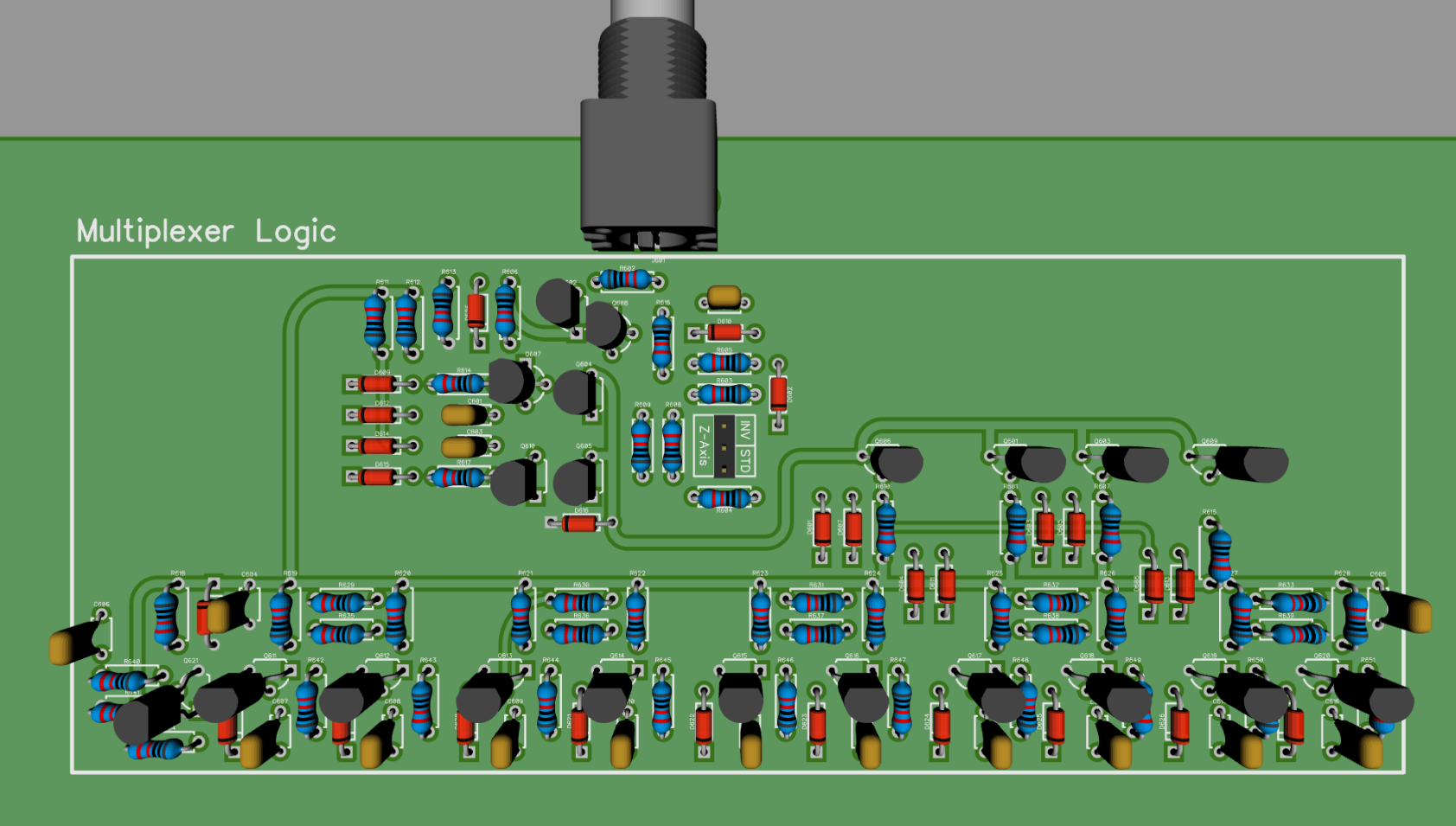
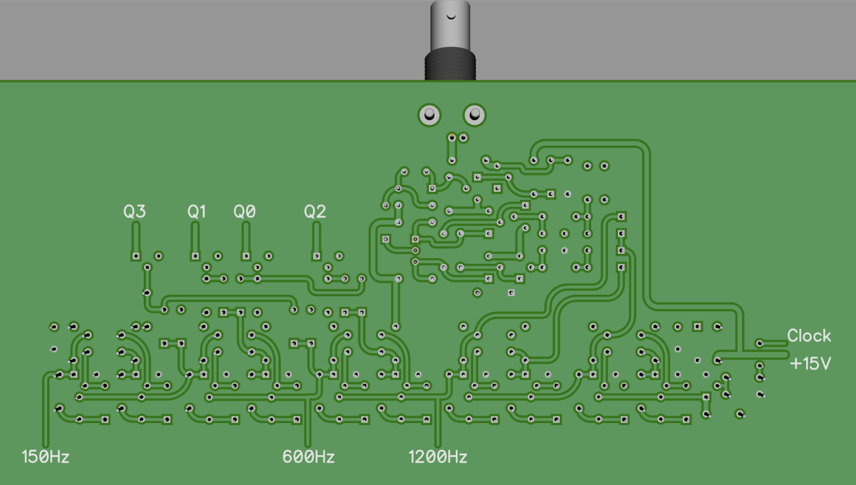
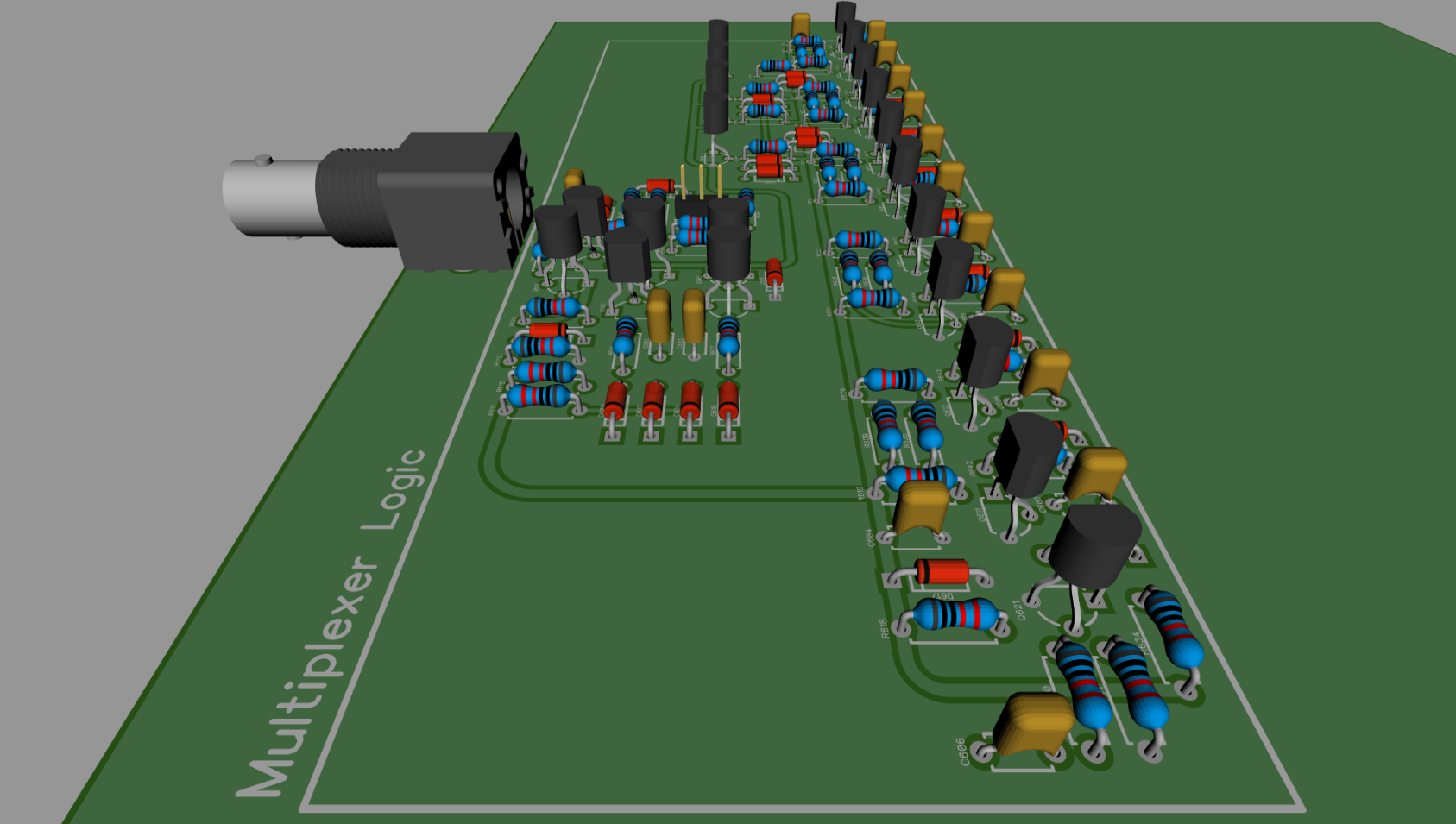 http://timb.us/PDF/Scope_Pong_Multiplexer_Logic.pdf
I didn't get the Function Generator section done, but I'm close there as well. (I ran into some routing constraints so took a break; I've since figured out a suitable route so I'll go back to it tonight and finish up.)
-
-
I would stay away from 7 segment displays and any logic IC for counting and 7 seg decoding. I would like to keep everything discrete. Either 10 leds for each player using simple transistors to shift increment the score, or, with the exact same transistor shift increment, provided the output transistors are open-collector and can withstand the HV, send the 10 outputs to nixie tubes for a 0 to 9 count display.
Basically, 1 all transistor circuit, 2 optional displays, 1 LV for leds, of with an HV supply, nice numeric tube display.
Some sort of 1-of-n ring counter would certainly be easier, though a diode matrix could do 7-seg decode easily from a 1-of-x output.
-
#198 Reply
Posted by
timb
on 01 Apr, 2017 10:23
-
If you're going to the effort of doing a PCB, some suggestions :
Where power comes into each section, run it through a pair of pads with a track linking them, so for faultfinding you can cut and re-link neatly, or fit a 2x2 0.1" pin header to take shorting jumpers.
How easy would it be to add I/O for an optional on-screen scoring add-on board?
I think onscreen digits would be doable with a diode matrix for characters,or you could do LED displays (minitron filament displays for period accuracy), or nixies. A long time ago ISTR seeing an idea from the 60's for vector digit generation using various LC circuits to combine sine & cosines to form digits for vector displays.
I think one big board will have some visual appeal - perhaps a layout that can easily be done as a large PCB or split into smaller stacked ones.
If you're looking towards a kit, it would be nice if there was an option to avoid dealing with mains - might it be feasible to do something like a rail splitter to run from a 24VDC power brick?
A possible issue here is that some of these PSUs have output -ve connected to mains earth. Maybe a +12 to -12 inverter?
Or maybe from 12VAC from an off-the-shelf halogen lighting transformer, with a charge pump inverter for the -ve rail.
Already planned on adding solder pad power links for each section.
It would be difficult to do this as a single, large PCB due to cost reasons. You'd need at least a 400x400mm PCB; I did research this but costs seem to start going way up once you go over 200x200. My current plan is to stack two 200x200mm boards.
I have a source for 24VCT plug packs, so that could always be an option. You could always also use two separate 18VDC laptop type adapters or a bench supply.
I'll make sure the nets needed for scoring are brought out to the board to board headers, so a scoring add-on could be plugged in.
-
#199 Reply
Posted by
timb
on 01 Apr, 2017 10:31
-
Tim, great work, if you're fussy about layouts they do take some real time.
May I ask what size annular ring size you're using and the pad hole size ?
I've had some pads lift when reworking PCB's and as a result my preference is for larger pads to minimize the chance of this.
When I can I stick with 100 mil and maybe alter the shape from round if more clearances are needed.
As promised:
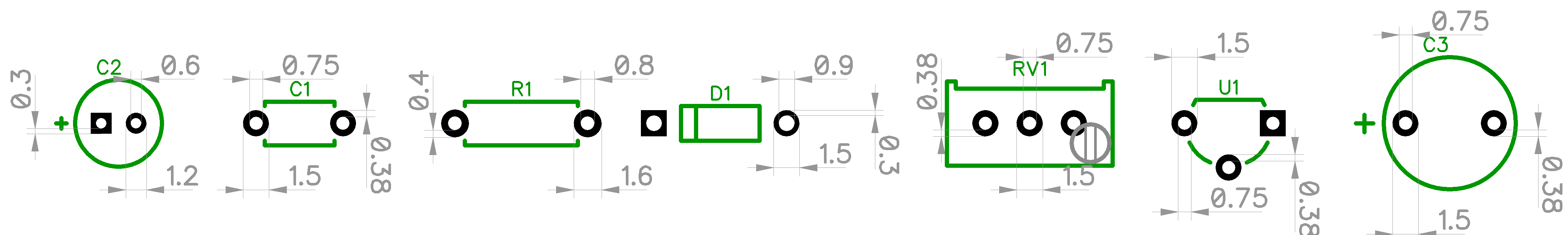 http://timb.us/PDF/Scope_Pong_Pad_Sizes.pdf

