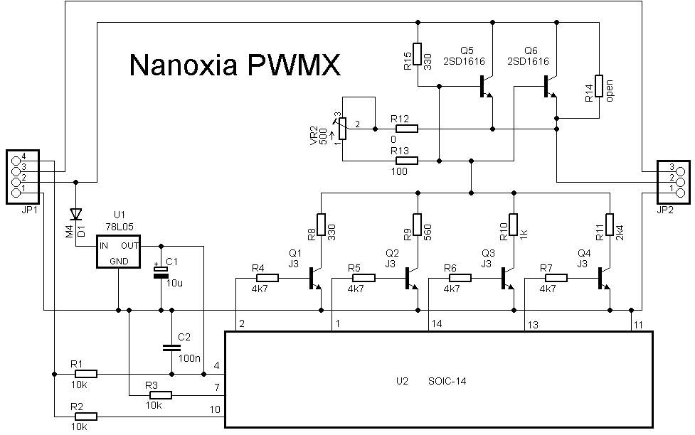
I think it is rather poor design. The microcontroller controls a crude 4 bit DAC, so no more than 16 speeds - maybe less. The transistors may not share current equally (no emitter resistors). Linear operation is inefficient and will drop about 1 volt at max speed.
wow! thats pretty bad!
maybe its that hard for him to find a good flux or reflow machine supply (like me

). so need to DIY from what he already has (solder only). the PCB is nice though.
Build quality is typical for a low cost product.
PCB is thin and slightly warped. It does not appear to be FR4.
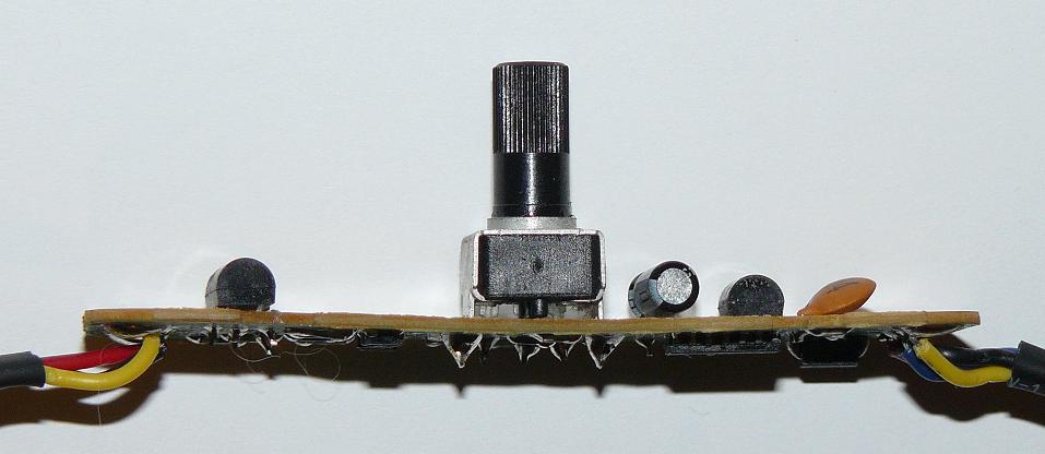
Wave soldered (not reflow), flux residue on board.

Some flux on top side too. Pot is smooth and tight.
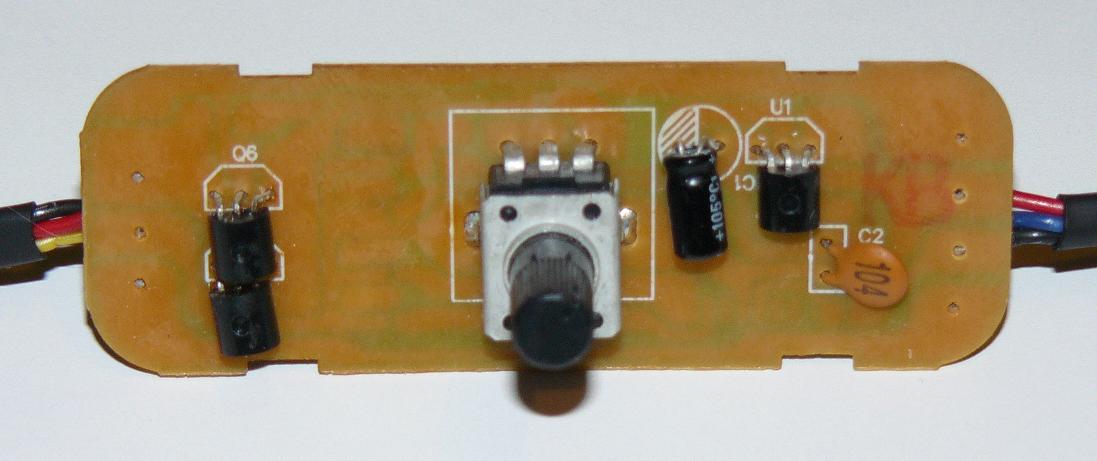
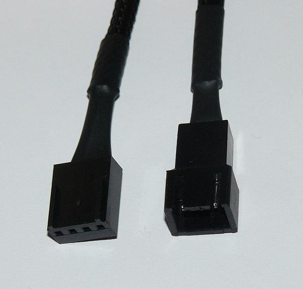
Connectors are keyed. Heat shrink, but no strain relief.
Wave soldered (not reflow), flux residue on board.
not hand soldered huh! well ok... thats UGLY! my hands are better than that.
I do not believe this ... even more pictures .

Can any one predict the output in Amperes ? If I use as 12V input from molex ( so to not stress the fan header ) and the rest cables normally connected !!
It looks that there is four output transistors named as J3.
The PWM reference circuitry , have as info , that the output circuitry it must be capable to offer even 2A ,
for 1-2 ms ( starting current ) .
edit: Those must be called as JFET , found one description about output as 35mA/V .
At 12V X 0.35 = 420mA its one By four times = 1680mA ( yep that's sounds close enough )

Q1 to Q4 are NPN as shown in the schematic. They may be
S9013 or
MMS9013. There is no standard for marking SOT-23 package components.
Q5 and Q6 carry current to the fan. I estimate they will be warm at 100 mA, hot at 200 mA and dead at 400 mA (continuous @ 6V to fan).
What about replacing those with better ones ... is there any suggestion.
I need 600mA continuous @12v , and 2A peak for 2 milliseconds.
(the size does no matter )
The fan will draw less current at lower voltage, so it may be OK as-is. Try it and see what happens. If it blows up then mod it.
A CFP (Sziklai) output using a PNP transistor (Q6) in a TO-220 package should be good for 2A or more with a small heat sink.
Modified schematic...

Nice

In the primary design Q5+Q6 works in parallel .
In the last the Q5 drivers the larger Q6.
I will have a look about the BD part specs on my vrt books.
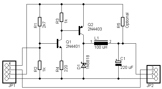
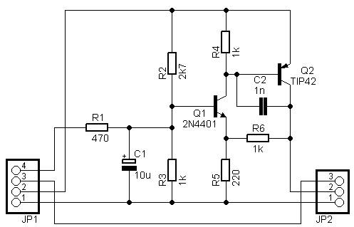
I built a circuit to characterize PWM to voltage converters.
Schematic
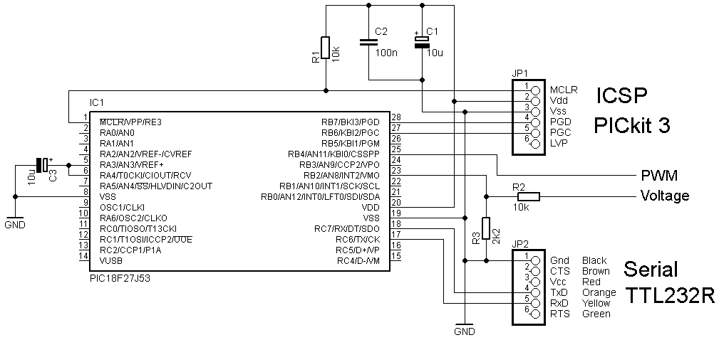 Source code, schematic, and captured data
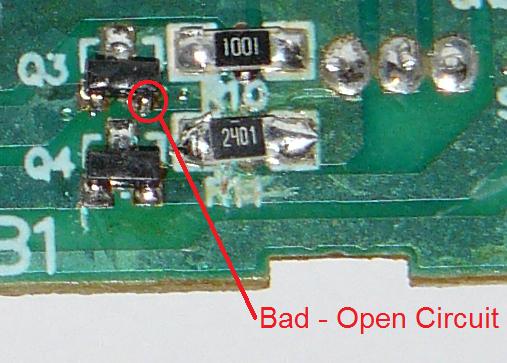
The first test showed that the Nanoxia PWMX was not working correctly. The problem was bad solder on the emitter of Q3.
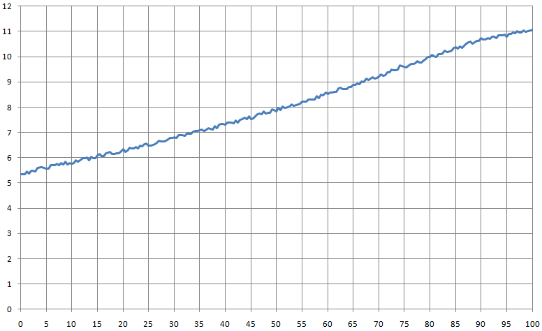
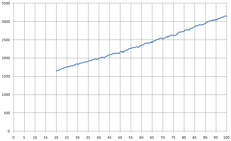
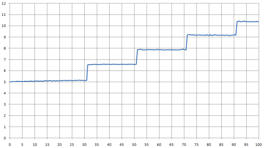
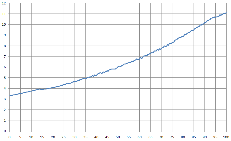
Plot showing Voltage (left axis) vs. PWM % (bottom axis).

After fix. Pot set to max fan speed (full CW).

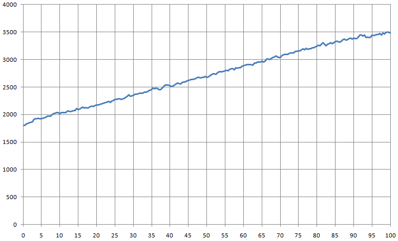
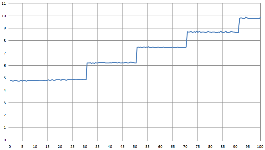
Pot set to middle of rotation.
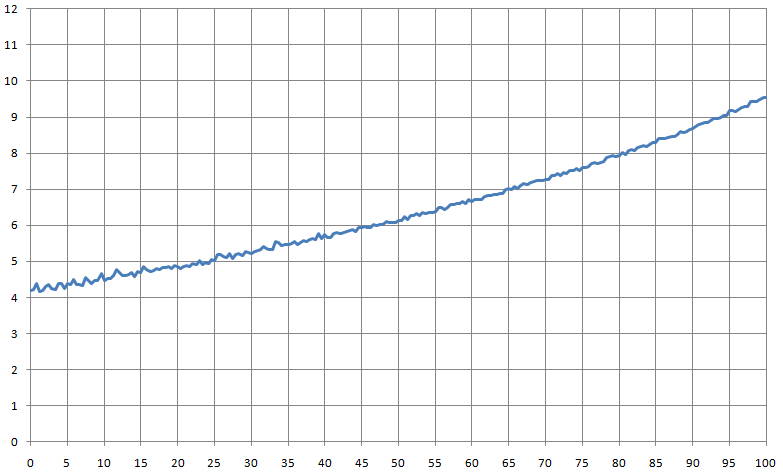
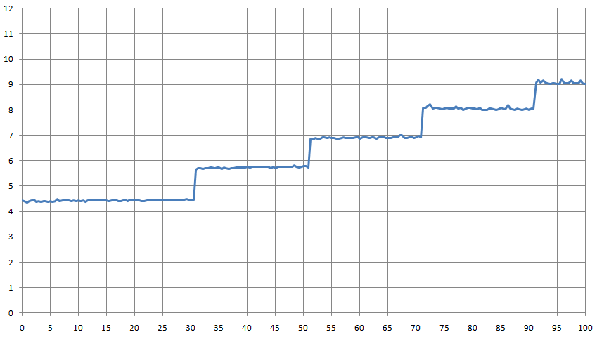
Pot set to min fan speed (full CCW).
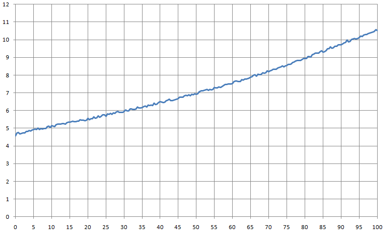
Pot set to middle voltage.
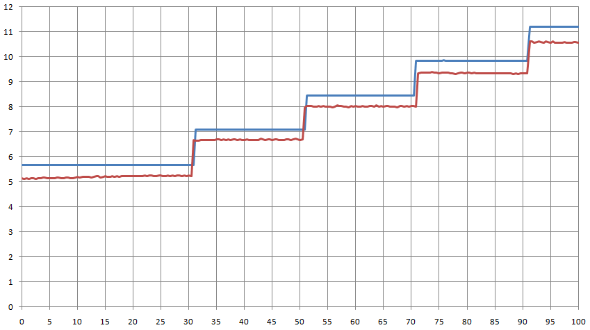
Comparison. Max (violet), middle rotation (red), middle voltage (green), min (blue).
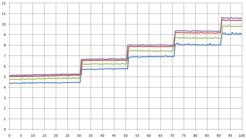
Comparison of output with no fan (blue) and fan that draws 220 mA @ 12 volts (red).
Noise in the plots is due to fan commutation. There is no noise with no fan connected.
Tests at 20, 25 and 30 kHz. It measures both the on and off duration of the pulse. Very good.

oPossum,
if you had get in to the "Win a UEi DM391 Multimeter" thread,
I wish with all my hart, to get it
( its an long shot, but this is my wish )
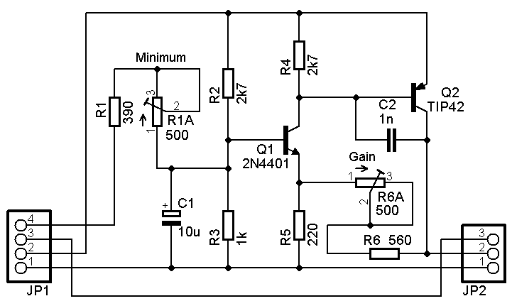
I built this on a breadboard...
Tested with 220 mA fan. Results...
Note: Max current with Q2 2N4403 or similar is ~300 mA. Use larger Darlington PNP like TIP125 for more current.
Use R5 if fan must run below 20% PWM.
Designed, built, tested, indication of possible modifications. Great job, oPossum!
I can see only one part missing from the last design, the pot that I will control the final DC output even at 100% PWM .
(Like the PWMX does.)
( About the 2N4401 i have the equivalent BC337 next to me X2 )
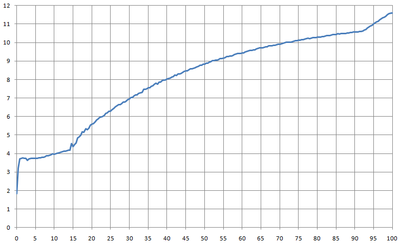
I built this on a breadboard...
Tested with 220 mA fan. Results...
Fan runs at 25%, but tach does not work until 32%
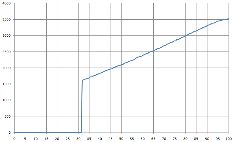
Increase R1 to move start of curve up (so fan will run at lower PWM %). Decrease R6 to move entire curve down (so max speed is reduced).
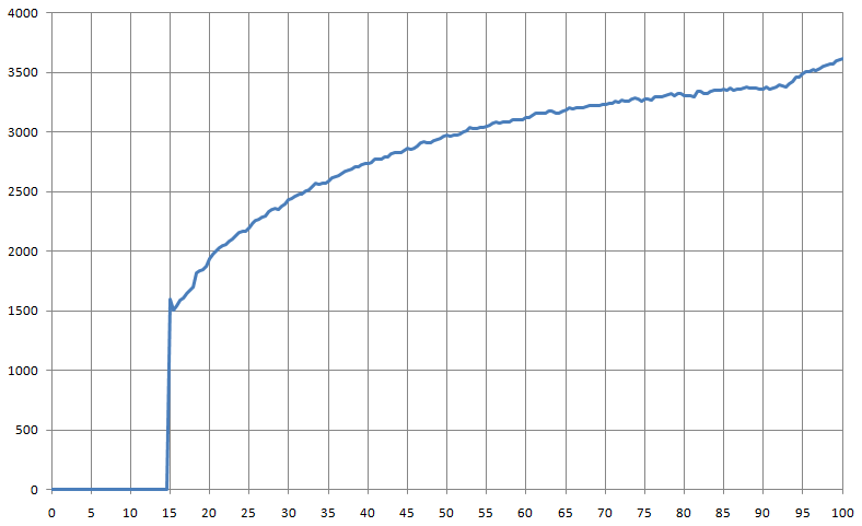
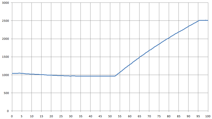
PWM % vs RPM for genuine Intel 4 wire fan supplied with boxed Pentium 4 LGA775
The actual dream or wish , of any one who needs this design.
Are to use an 120mm fan with this circuitry .
The only problem are , that even the best ever 120mm fan it will start to become audible above the 1000-1200rpm .
And and so the 20%PWM ( start point it should represent the 600rpm ) and the 100% PWM ,
the 1400rpm mark.
I bet that with this design , and the adjustment points R1 & R6 , everything looks possible.
I think that I am going to build it.
The German that I ordered the PWMX , he did not shipped anything after all this days, with the excuse that he run out of stock about the PWMX , and he waits to restock.
I had kick his **** today ( after of two weeks of patience ) , and put the Paypal on his tail, so to get my payment back.