Sorry, i forgot about this topic. Problem is solved long ago. New STM, programmed and work like a charm.
Thanks
floobydust for all support and help.
I attached here the finished schematic for this black board, if anyone will need it in future.
In the meantime, if that black board was dead, i ordered other version.
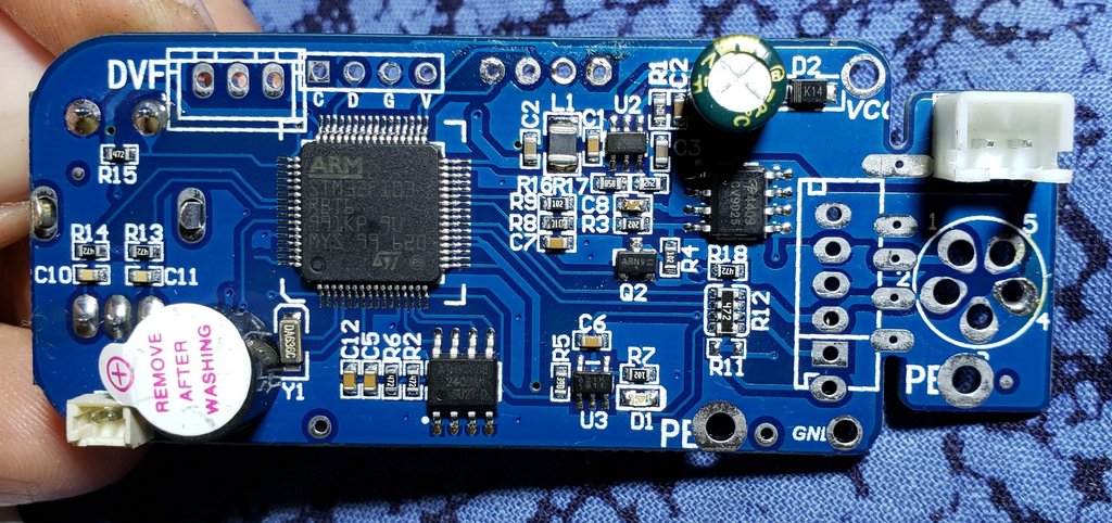
Blue PCB 'Ve2.1S' r2 KSGER Version (LWFP-64).
Problems here too. Controller worked just fine until i connected the 3V battery.
Suddenly it does nothing. Just the green led from the back lights continuously. The ST-link utility does not see it either, so MCU is not working.
i'm really lucky with these boards...

I would check the battery cable has the right polarity. Maybe it is backwards? (-) is to outside of pcb edge.
Did you order these from the KSGER store, or some shady dark alley? Sometimes I think they ship different quality boards.
This Ve2.12S board has the mystery op-amp "621K" that the Russians have problems with, low accuracy on temperature. What does it report for H/W and S/W version?
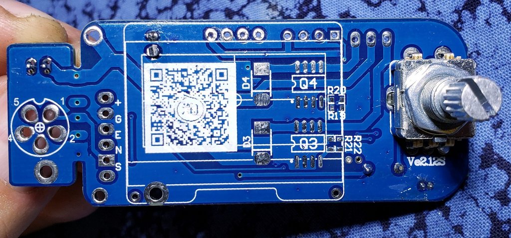
Thanks for the Ve2.12S pictures, another schematic to draw lol.
Problems here too. Controller worked just fine until i connected the 3V battery.
Suddenly it does nothing. Just the green led from the back lights continuosly. The ST-link utility does not see it either, so MCU is not working.
i'm really lucky with these boards...
After disconnecting the battery, the controller does not work?
Maybe you have a large static charge on you and damage the MCU with it?
Or when connecting the board bent and damaged the soldering.
The STM will not respond to the programmer when properly connected (preferably with an nReset wire) if it is dead or has no power supply. Have you checked the power supply?
I would check the battery cable has the right polarity. Maybe it is backwards? (-) is to outside of pcb edge.
I checked. Polarity is good.
Did you order these from the KSGER store, or some shady dark alley? Sometimes I think they ship different quality boards.
They are from KSGER stores (there are 2-3 stores on Ali).
This Ve2.12S board has the mystery op-amp "621K" that the Russians have problems with, low accuracy on temperature. What does it report for H/W and S/W version?
As i remember, it's just the usual H/W 2.0, S/W 2.12, MCU STM32F103 (now can't check it anymore). I had it connected in the past with ST-link without problems.
Can the op-amp be replaced with the 8551? I ordered a few pieces.
Thanks for the Ve2.12S pictures, another schematic to draw lol.
We'll do it, friend! I have more accurate pictures, will send you over if you want. I think is a bit different (or not) from your Ve2.12S.
After disconnecting the battery, the controller does not work?
No. Only the LED lights continuously after 2s from connecting the power and no tip connected.
Maybe you have a large static charge on you and damage the MCU with it?
Or when connecting the board bent and damaged the soldering.
I don't think i had any static charge, because in same time i played with the black board and he's ok. Anyway, i didn't touch the MCU.
Have you checked the power supply?
Yes, i have 3,3V on MCU.
But interesting is, i have only 1,4V in battery connector (without battery connected). On the good board i have 3,3V in it.
Solved this too!

Resoldered the quartz oscillator (didn't seem soldered right) and didn't start. But... at least i had again communication with ST-link.
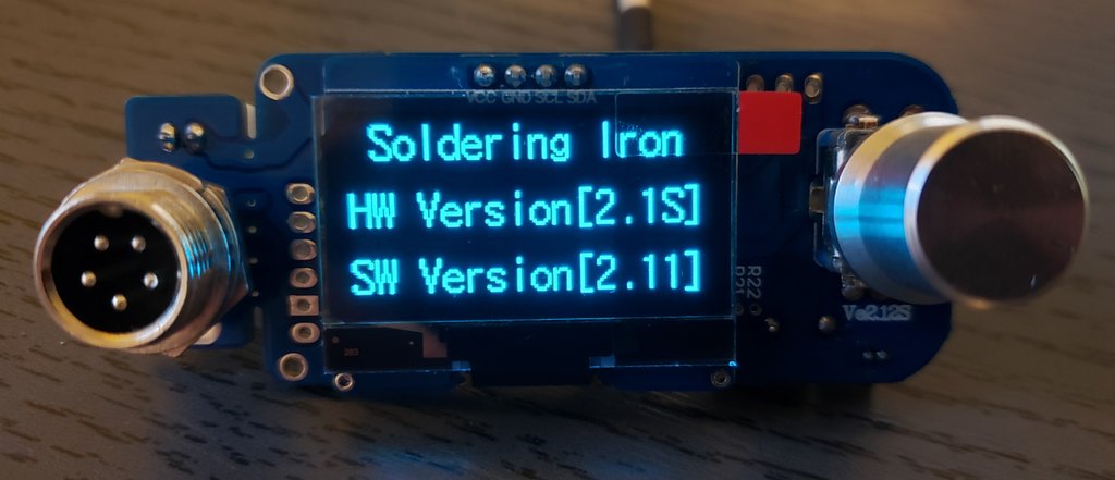
Tested all available fw and only one work: T12_v.2.1S_OLED1.3.
SW version is reported as 2.11.
Did you connect the nReset wire to the ST-Link, select a hardware Reset in the settings?
STM32 always starts after Reset on the built-in generator and an external faulty quartz does not prevent the programmer from seeing the MCU. But to do this, the programmer must be able to perform a Reset over the wire.
No, i did not.
Just resoldered the quartz and already had the communication with ST-Link.
In the meantime, if that black board was dead, i ordered other version. Blue PCB 'Ve2.1S' r2 KSGER Version (LWFP-64).
It's interesting that your version from the KSGER store has the STM32F101R
BT6, but the assembled one I ordered this month from the "KSGER Store" on Amazon advertised as V2.1S came with the identical blue PCB marked Ve2.12s on the silkscreen, but fitted with an STM32F101R
8T6 chip, and Q3 and D3 installed to control a vacuum pump. The info screen says
"Soldering Iron
HW Version 2.1S
SW Version 2.10"
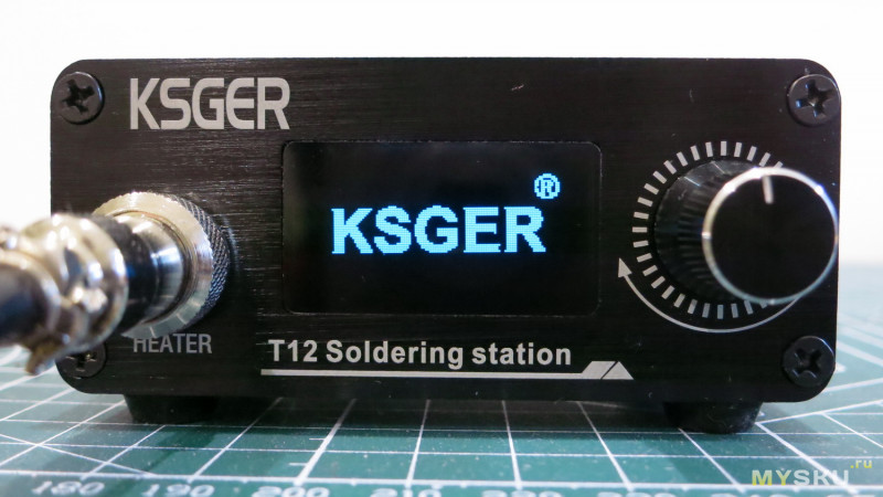
And I noticed that on some pictures of KSGER irons that I've seen posted, there is a KSGER logo on the screen. Mine doesn't have a KSGER logo on the bootup screen. Does yours have a KSGER logo on the boot screen?
My Ve2.12s blue controller has the STM32F103, not F101 MCU.
The KSGER logo i have never seen. How is it look like?
My Ve2.12s blue controller has the STM32F103, not F101 MCU.
Yes, you're right. I didn't look carefully enough at your photo

. So that's another difference in these "KSGER" Ve2.12S versions.
Here is the picture from
a Russian forum with the KSGER logo:
Nice.
I have no such a logo. It all depends on firmware. The chinese did not copy all the details...
Maybe DavidAlfa could help us out, adding boot logo to certain firmwares.
RB and R8 are the same thing, the R8 has part of flash not tested or defective, therebefore sold as 64KB
What do you say David, can you add a boot logo to firmware i use?
I know that the only difference between the R8 and the RB within the same series is the amount of memory, but what I don't understand is if the F101 has enough features to run the iron, why do they put the F103 in some of their controllers?
The other thing I wonder about is how they fit the the stock firmware into F101R8 controllers like mine, because the stock firmware files I've looked at have a binary size of about ~75KB. So are they putting 75K of firmware in an MCU with only 64K of tested memory, and risking malfunction, or are they taking something out of their firmware to make it fit the smaller 64K memory space available?
Easy, if the flash is defective, it will fail the verification.
They use whatever is cheaper in that moment, simple as that.
Adding a logo would be a huge and hard work, patching a compiled fw needs a knowledge in assembler programming that I don't have..
Easy, if the flash is defective, it will fail the verification.
The problem with that approach is that although the flash memory may pass verification under the specific conditions of temperature and voltage that they test it at in their factory, that doesn't necessarily mean that it will work over its full rated temperature and voltage range that it could be exposed to after hours of operation inside a sealed case without ventilation. It could still be partially defective, and might fail under other conditions. Maybe that accounts for the reports of peoples' controllers freezing, and irons spontaneously glowing red hot. Borderline or defective flash memory is very sensitive to environmental conditions, and chips that can't be read at all at one temperature may read out perfectly at another higher or lower temperature.
I couldn't imagine any of the reputable soldering iron manufacturers stuffing 75K of firmware into a chip that was marked and sold by its manufacturer as a 64K device, even if it happened to pass verification.
Sure, that behavior is not profesional. But for the DIYer it's a cool hack.
These glowing irons are pretty much software bugs, they didn't consider certain possibilities and it stucks somewhere.
I've had few of these, mainly caused by hard faults or the main error handler.
So I set some debugging output there, and disable the pwm when It happens.
Didn't had any more iron "bulbs" haha.
So these boards can really control JBC tips?
My JBC 245 tip+handle arrived and i would give it a try.
Merry Xmas everyone!