500 picosecond/2Ghz is right for a sinus signal but I have some doubts you will make with this a fast rising edge pulse.
500 picosecond/2Ghz is right for a sinus signal but I have some doubts you will make with this a fast rising edge pulse.
I know at least this level of performance is possible because that is about what my Tektronix PG506 achieves. I would hope to do better with surface mount construction and faster transistors.
The alternative is the often discussed charge line avalanche pulse generator. I have considered a step recovery or non-linear transmission line design but I know less about them and I suspect step recovery diodes would need to be qualified from existing and available varactor or PIN diodes.
Why not just put a MMIC wideband amplifier behind the fast comparator?
500 picosecond/2Ghz is right for a sinus signal but I have some doubts you will make with this a fast rising edge pulse.
I know at least this level of performance is possible because that is about what my Tektronix PG506 achieves. I would hope to do better with surface mount construction and faster transistors.
The alternative is the often discussed charge line avalanche pulse generator. I have considered a step recovery or non-linear transmission line design but I know less about them and I suspect step recovery diodes would need to be qualified from existing and available varactor or PIN diodes.
I have a Tek PG506 (I have several module from Tek 500) and just did some test, 600ps and 200mV up to 2.7ns on 1V, maybe there something wrong with my unit but rising time change with amplitude. I order one week ago extension cables to check/calibrate all my Tek 500 modules.
Why not just put a MMIC wideband amplifier behind the fast comparator?
You mean just to improve the output level without changing the transition time?
There has been a discussion going on (not here) about how to do something like this with DC to X frequency response and better than 5 volt peak-to-peak levels. AC coupling cannot be used without a parallel low frequency path and DC coupling cannot be used without a similar DC servo controlling a floating output stage and bias. Given that extra complexity, I am not sure it is worthwhile over the alternative open-loop designs and I suspect transient response if important would suffer.
500 picosecond/2Ghz is right for a sinus signal but I have some doubts you will make with this a fast rising edge pulse.
I know at least this level of performance is possible because that is about what my Tektronix PG506 achieves. I would hope to do better with surface mount construction and faster transistors.
The alternative is the often discussed charge line avalanche pulse generator. I have considered a step recovery or non-linear transmission line design but I know less about them and I suspect step recovery diodes would need to be qualified from existing and available varactor or PIN diodes.
I have a Tek PG506 (I have several module from Tek 500) and just did some test, 600ps and 200mV up to 2.7ns on 1V, maybe there something wrong with my unit but rising time change with amplitude. I order one week ago extension cables to check/calibrate all my Tek 500 modules.
I think you have something wrong. The transition time on mine does not change significantly with level and 2.7 nanoseconds is way outside of the maximum specification. Maybe you were looking at the wrong edge on that particular fast transition output? There are two outputs with one having a fast rise and the other having a fast fall.
Below a table with the different technology and rise time of the pulse:
20 volts is high enough to require compromising the RF performance of the transistor. Besides the PG506 which easily beats that with discrete transistors albeit with only a 1 volt output, the various Tektronix 7000 standardizers do much better than 2.5 nanoseconds with discrete designs and again are lower voltage.
Even the Picosecond Pulse Labs 6110 and the NTSB design that it is based on are faster than that.
Step recovery diodes sure look good. Anybody know where to buy them?
BTW, I'm also working on a sampling head, however if I get up to 1GHz I will be very happy.
The sampling strobe is generated with an avalanche transistor for the moment. Trigger detection and everything else up to the puls generation is done with ECL logic.
I would want to at least duplicate the performance of the Tektronix S-2 sampling head at about 4 GHz. Apparently it was limited by the diodes it used and changing them can improve it significantly.
Has anybody tried using a transmission line (25 ohms?) to replace the sampling capacitance at the output of the bridge? It seems like that would give better sampling efficiency.
So you would keep it open ended and turn the bridge off before the reflection hits and then let it bounce around for a bit to equalize?
So you would keep it open ended and turn the bridge off before the reflection hits and then let it bounce around for a bit to equalize?
If the sampling gate width is adjusted to be the same as the transit time, then ideally it will not bounce at all. One of my sampling books discusses this implementation but I know of no real world examples.
Isn't this close to what they are doing in the Tek S-4?
Isn't this close to what they are doing in the Tek S-4?
I do not think so. The Tektronix S-4 and S-6 (others?) use a traveling wave gate design where a segment of the transmission line carrying the signal is disconnected by the bridge diodes. The sampling gate width depends on the transmission line length and the trailing edge transition time of the strobe but not the strobe width which is an advantage for fast operation. Tektronix published detailed articles about how this works and I may not be describing it well.
The open transmission line design replaces the sampling capacitance with a transmission line. Maybe it has no advantage over just using capacitance. When I get around to it, I will certainly try it. It is described in "Circuits for Electronic Instrumentation" by T. H. O'Dell which is also a reference for strobe generation and sampling circuits in general although not the traveling wave gate type.
The biggest problem when desigining these kind of scopes is a trigger system with ultra low jitter .
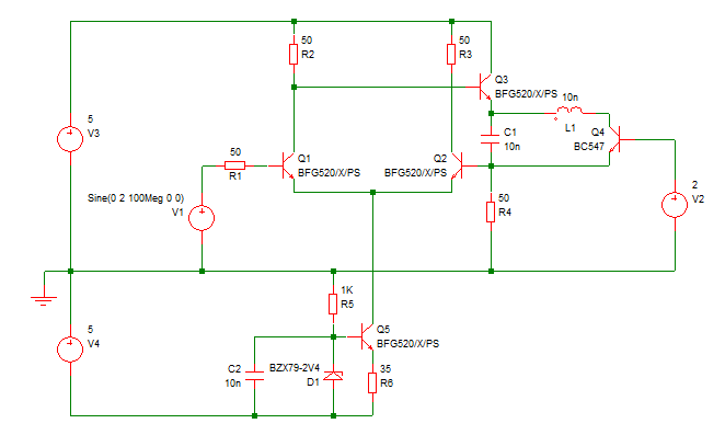
Is it really so hard? Obviously the expensive comparators Darwin uses can do it ... but couldn't you do something with discrete transistors and regenerative feedback like this as well :
BTW, I found
a really nice article describing the LLNL sampler (starts on page 36).
PS. hmm the amount of negative current which that circuit tries to push through Q3's emitter can't be healthy, but you could probably find someone familiar with time domain RF circuits to get a better circuit ... but these kind of Schmitt trigger like circuits can work at ~ 200 picosecond rise/fall times, described in papers, with a decent rise time on the input signal jitter shouldn't be a real problem at that point (in simulation noise has nearly no effect).
I think at least HP had some sampling oscilloscopes that worked like that as well. I know I have read about that type of design before.
I think the jitter problem comes down to the lack of power supply rejection from the single ended logic which both processes the trigger and generates the strobe. Differential comparators have natural power supply rejection and use an external reference for their switching threshold. Some ECL has an external signal reference that can be used to add power supply rejection but I think discrete designs still seem to have an advantage over ECL because their ground and power supply returns can be controlled. ECL differential input line receivers may useful however.

 but I manage to do it, I try with hot air
  , I have an oven but for one prototype with a few components