My E7495 works OK, but is missing a few parts. Does anyone have parts they would be willing to sell? The main thing is that the power meter board is installed, but the two ribbon cables (one presumably going to the case-mounted connector) are missing, along with the connector.
I also need a main case gasket and the threaded insert that the battery door retaining screw threads into.
Thanks.
Richard
Is there a way to hack the software or firmware in the E7495 so that the lower frequency limit for the one port and two port loss can be set lower than 375 MHz? Being able to cover the ham HF bands would be nice.
Richard
Hello Friend
you can describe, how to do full options
Is there a way to hack the software or firmware in the E7495 so that the lower frequency limit for the one port and two port loss can be set lower than 375 MHz? Being able to cover the ham HF bands would be nice.
Richard
The lower frequency limit can be changed by editing a text file however I believe it has been documented in this thread that lowering it causes the generator to crash when it boots.
in the reply #148:
"I played around with the files in /flash/egServer/Dragonfly/Receivers, like E7495A and CPXSRC. You can indeed change things here and sometimes see the effects (e.g. you can change E7495A to have Freq Range be 3000e6, and it makes it possible to enter that value). However, some of these changes will have no effect for other reasons (here, I assume it's because there is actually a filter which sharply cuts off at ~ 2.7GHz). However however, I could not find a way to try and make the signal generator make higher or lower frequency signals"
Maybe we should do more experiments with this and document if it works below 375 MHz for the one port and two port measurements.
I've lowered the gen frequency on its big brother the N1996A and it works fine but I don't have an E7495A to experiment with.
That's great! Can you say how you did that?
Richard
AE6XO
Regarding "I've lowered the gen frequency on its big brother the N1996A and it works fine but I don't have an E7495A to experiment with."
Could you describe what "it works fine" means? have you done 2-port or 1-port measurements at a lower frequency range (let's say 1MHz or 10MHz) and have you compared the measurement with other VNA?
Do you remember what exact file and parameter you have changed?
The biggest difference is that the N1996A gen out starts at 10 MHz when stock. I lowered it to 1 MHz and it still normalized fine. Its performance was just fine for return loss measurements of HF antennas.
The biggest difference is that the N1996A gen out starts at 10 MHz when stock. I lowered it to 1 MHz and it still normalized fine. Its performance was just fine for return loss measurements of HF antennas.
That. There is a model description file in the N1996A firmware that lists the frequency range of the freq generator. If you change the starting freq from 10 to 1 MHz it will obey.
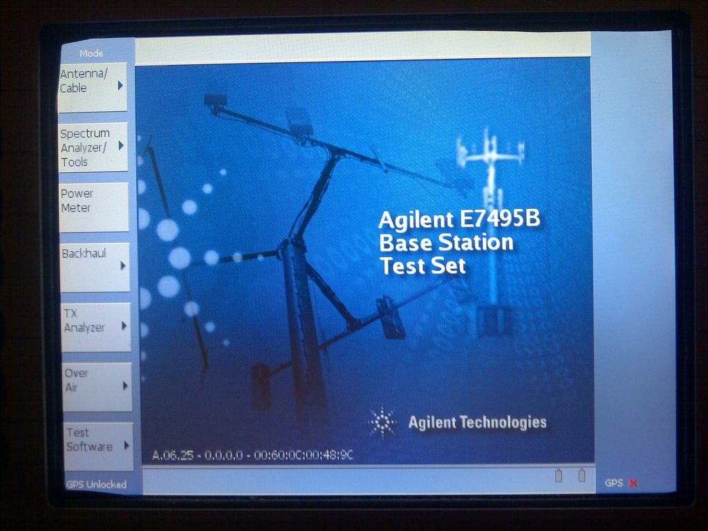
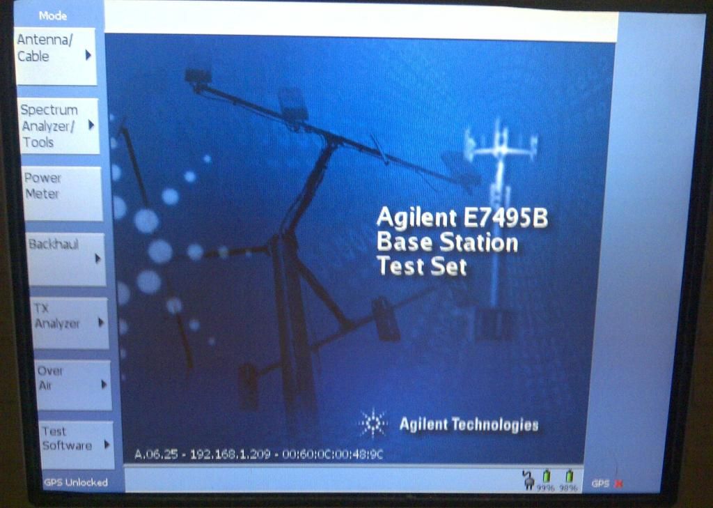
Hi everyone. I'm the proud owner of this instrument and recently discovered this thread. I've read through the entire post several times and have learned a great deal thanks to everyone's generous attitudes toward sharing their knowledge and experience.
My particular E7495 was running an ancient firmware of 1.60. Thanks to this forum I was able to easily obtain the now scarce 6.25 firmware package and had little trouble installing this once I got my hands on a compact flash card. The next step was dusting off my linux skills which are no where near as developed as the people in this thread but turned out to be adequate to transfer the required binaries and use a hex editor to manipulate them as described. I have hit a snag unfortunately. I have the same problem reported by another user where I am unable to navigate to the second page of system options due to a system hang when the more options soft key is pressed. I understand the cause of this, at least in that other poster's situation was due to his license file having no entries after "SIGN=".
I thought the solution for me would be that simple as well but it seems I have a unique problem here. My license file does not contain erroneous entries, in fact it seems to be missing information. I have re-installed the 6.25 firmware 2 times and then tried a third time with the recovery script method. This third time I tried a little experiment and modified the License file by changing the values of the populated features and then using the recovery script after moving the file to /flash/egServer/license/elgato.lic . After the update I checked the file and discovered apparently at least in my case this license file is not touched in the update process as my license file had the changes I had made in a hex editor.
I'm not sure how I ended up with what I suspect is a corrupted license file but here I am. I can go to the install license screen when I have a binary with the stock hex values in the 337A7C offset and see all the correct options (i.e. over the air EVDO and so on) but in my original license file these options aren't listed.
Can someone here please take the time when convenient to view my transferred License file and maybe share their thoughts on whether a license file from another machine has any hope of being transplanted into mine and confirm that my file is in fact somehow corrupted?
Thanks in advance to anyone who can spare some time to read all this and help me out! And if something I've done or tried to explain doesn't make sense then thanks too for your patience. I've attached the file as a .txt to meet the forums attachment requirement.
Was there a value after the SIGN= in the original file? That is the key to unlock the feature together with the HOST string:
FEATURE 503 agilent 1.000 permanent uncounted \
HOSTID=ID_STRING=12345678 SIGN=F1CE2A146BC6
The HOSTID is the ID of your instrument which is the same as in the file hostid in the same folder, and the SIGN is the key that was entered to activate the option.
Sometimes there are some default entries in there that don't have a SIGN so normally they do nothing. But when the patch is applied they all start to work...
Also, I see a hex "F0" value behind the sign for option 210 which I'm sure does not belong there, and a lot of hex "00" in every SIGN=
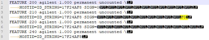
Try to put 12 digits (0-F) after every SIGN= and try again.
Thanks for the reply, I just realized I mistakenly uploaded the file I had tried to modify which explains the FO entry you pointed out. I tried entering 00 in the fields after sign and must have missed that one. Just to clarify, any value can exist after these entries? obviously if I screw up the correct formatting by entering information into the wrong field as I've done here that matters. But by putting say 00 A1 B1...etc into the field or all 00 00 00 entries as I tried here that is how I fix the file?
Sorry to be dense, I'm struggling a little determining how exactly the file should look....
Yes you can pick any value(s) for the SIGN= string, the patch disables the check on this value. However, I think that invalid values or length can still do strange things, I don't remember if there was any other checking on this value when I created the patch long ago. In any case, don't use HEX 00 values or other unreadable stuff in there but use 12 characters from '01234567890ABCDEF'.
[Edit]
I don't see anything wrong with your license file apart from the fact that the last option (240) is missing the SIGN= entry, this could well be the problem.
It looks like it contains the following options:
200=CDMA / CDMA 2000 Analyzer
210=CDMA Over Air Test
220=Channel Scanner
240=W-CDMA Analyzer
I've just edited the elgato.lic file to include the last sign= portion that was missing. Thank you for finding that missing portion and helping me to fix my mistake. This as you likely already knew has fixed the menu option issue and I can now install all options. I've learned a good amount reading this thread and for that I'm forever grateful.
I have periodically at different levels of brightness blinking display. I had to find a reason. The culprit was the inverter. To eliminate the defect, it is necessary to solder the resistor of 1 mom-2 mom in parallel with the capacitor C20. (Between 4 and 5 pin BA9743A).
Well, I forgot an important question. I just got my unit today, so before I do something stupid...
- Is the power supply center-pin positive? Yes*.
* I looked through this thread more carefully; it's 9-24V DC, somewhere between 3 and 5 amps; center-pin positive.
The DC plug is 5.5 x 2.5mm center positive. The most common plug size is 5.5 x 2.1 and it does not fit unless you push it very hard, which can break the DC jack.
It is the gasket that sits between the LCD module and a transparent plastic panel that protects the screen. I have not fixed mine yet, but I took the front panel apart and I verified that is the black gasket. It should be easily fixable, no need to purchase a new LCD module. I have seen many units on eBay with the same issue.
True... have find out that, when I finally opened the unit to verify LCD type.
Has anyone had any luck using either the serial ports or gpio? I was hoping to get it to spit out useful data on the serial port.
Has anyone had any luck using either the serial ports or gpio? I was hoping to get it to spit out useful data on the serial port.
There should be no problem accessing serial port from inside of E7495. What kind of data are you going to spit out?
I'd like to be able to export gps and an average signal level. Something where I could do a rough drive test.
Today during the boot my E7495B stopped to work. The unit was couple months in storage
during the whole summer.
The trouble is localized within PS DC/DC picture with model details in attachment.
Looking for that module, designated in service manual like:
Power supply interface board A4A4or whole unit E7495 for parts....
PM pls, located within EU
The trouble is localized within PS DC/DC picture with model details in attachment.
My E7495A refused to work on battery. Now I regret that I dig into this. It took so much time...
The issue that was looking like a component failure appeared to be a pure software thing.
There is some SMBUS/Smart battery ugliness. Anyway, now I know quite a lot about this module.
I can help with diagnostics and repair.
Here's PIC16F877 pin map to start with. It's not complete and may have some mistakes, but it's at least something.
P/N     NAME    DIR     FUNCTION                                        CONNECTIONS
 1      RC7     I       UART RX                                         J10/5
 2      RD4     O       BATT LED                                        U10
 3      RD5     O       BATT LED                                        U10
 4      RD6     O       BATT LED                                        U10
 5      RD7     O       BATT LED                                        U10
 6      VSS     -
 7      VDD     +
 8      RB0     I       LOBAT(LOW)
 9      RB1     O       3DM(LOW)
10      RB2     O       DCIN (HI)
11      RB3     O       PWR ON LED                                      J20/10
12      NC      x
13      NC      x
14      RB4     I       START OF BATTERY MONITORING?                    J52/4, R96
15      RB5     O       BATDIS(LOW)
16      RB6     O       SUSPEND to ADS?                                 J6/1, J55/2
17      RB7     O       STBY PWR ON (LOW), STDBY LED (LOW)              U101, U11 - J20/7
18      RST     R
19      RA0     A       BATT TEMP
20      RA1     A       BATT TEMP
21      RA2     O       BATT TEMP STROBE
22      RA3     I       CONFIG JUMPER                                   J11/1
23      RA4     I       DCIN DETECT                                     U1
24      RA5     O       BATT TEMP STROBE
25      RE0     A       3.3V SENSE                                      100K - J5/5,6
26      RE1     I       PWR SW                                          U203, J20/9
27      RE2     I       ADS POWER DETECT
28      VDD     +
29      VSS     -
30      X1      C       4MHz clock in                                   U100
31      X2      I       NOT USED
32      RC0     O       CHARGER OFF                                     100K - CR4, Q13 - Q12 - U8/2
33      NC      x
34      NC      x
35      RC1     O       adjusts PROG A of U7                            Q11 - 10K - U7/1
36      RC2     O       charger output voltage setting                  Q14 - ?K - U8/6(Vosense)
37      RC3     I/O     SCL                                             Q20, J52/3
38      RD0     O       CHGSEL
39      RD1     I       BACKLIGHT DISABLE? (NOT USED)                   100K to Q7, GND
40      RD2     O       BATSEL
41      RD3     O       MAIN POWER ON                                   18K to J5/10
42      RC4     I/O     SDA                                             Q16, J52/2
43      RC5     O       I2C BATT MULTIPLEX                              U13
44      RC6     O       UART TX                                         J10/3


Q16, Q19, Q7 = NPN MMBT3904 1AM
B
 C
E

PNP MMB3906 2A
B
 C
E

n-MOS 2N7002 702P

G
 D
S