-
A vertical arrangement that is better for the forum:

-
Very nice, really helpful to see them side by side like that. Did you do a sneaky mirror on the images to make them match?
The only very minor thing I can see is the arrows from the First LO out to the TG on the main board should be going the other way. -
Very nice, really helpful to see them side by side like that. Did you do a sneaky mirror on the images to make them match?
Yes, I had to flip the image in order to match them up because the new ones has the components on the other side to the previous SSA3000 board. -
Daves teardown thread:
https://www.eevblog.com/forum/blog/eevblog-1101-siglent-sva1015x-vna-teardown/
EEVblog video:
https://youtu.be/HxBcQDooAYs -
Dave, thanks for the teardown, that was quite interesting.
A few things to add, some might be trivial and some rather peculiar:
In contrary to the high bandwidth SSA3000 series, Siglent doesn't use the special Rogers (or equivalent) high frequency PCB material but rather some impedance-controlled FR4. That way, it's much cheaper to produce and it makes complete sense to have an "almost" single-board solution for the instrument. In that regards, it's very similar to the Rigol DSA815 design which covers the same frequency range.
In Dave's video at 19:02, there's a close-up of the Port1 interface shown. Since I didn't quite believe that Siglent got along without a directional coupler for their VNA functionality, I dared to have a closer look, see the attached screenshot. There is a tiny multilayer coupler installed (similar to this one https://www.mouser.de/datasheet/2/400/tdk_02022018_HHM22152A2_ver4_1(Oct.2017)-1284660.pdf), yet highly surprisingly it's not located directly at the port but behind a switch and an impedance matching network / attenuator. I wonder how good the isolation/directivity characteristics of the circuitry are. If you look at the efforts the "big brands" in their boat anchors took some 25+ years ago to achieve really good directivity (see attached photo of an opened-up coupler of a HP 85046B test set, belonging to a 8753C VNA), it's hard to believe that despite all the advances in microcircuitry, manufacturers were able to shrink an assembly that much without sacrificing some quality/performance... I may be wrong, though .
.
What's also quite peculiar is that apparently Siglent got away with a single receiver channel. In order to get a proper phase relation between the measured signal from the DUT and the output signal provided by the VNA, the VNA would have to make a correlation of a portion of the generator signal to the measurement signal. For that purpose, "classic" VNAs have at least two input channels, one of them labeled "R" for "Reference". Since the SVA1015X clearly has only a single channel (with some switching circuitry albeit), it must manage the comparison between reference and measurement signal via that single channel in a multiplexed manner, making sure that the generator's phase is stable enough while "looking" at the measurement signal that no siginificant phase error is introduced during that time.
Altogether, the SVA1015X appears to be a real "budget instrument", much more so than the SSA3000X and it's probably focused on the Radio Amateur or eductional market. Nothing wrong with that, I only agree with Dave that an instrument advertised as a VNA should include that function off-the-shelf and should not require the puchase af an additional, not really inexpensive option to be usable as a VNA.
Cheers,
Thomas
-
[...]yet highly surprisingly it's not located directly at the port but behind a switch and an impedance matching network / attenuator. I wonder how good the isolation/directivity characteristics of the circuitry are. If you look at the efforts the "big brands" in their boat anchors took some 25+ years ago to achieve really good directivity (see attached photo of an opened-up coupler of a HP 85046B test set, belonging to a 8753C VNA), it's hard to believe that despite all the advances in microcircuitry, manufacturers were able to shrink an assembly that much without sacrificing some quality/performance... I may be wrong, though
.
I thought the same last night after watching the video. Coupling will be horrible at the low frequency range, so I expect a low SNR. There is probably a reason for the lack of accuracy specs in the datasheetQuoteWhat's also quite peculiar is that apparently Siglent got away with a single receiver channel. In order to get a proper phase relation between the measured signal from the DUT and the output signal provided by the VNA, the VNA would have to make a correlation of a portion of the generator signal to the measurement signal. For that purpose, "classic" VNAs have at least two input channels, one of them labeled "R" for "Reference". Since the SVA1015X clearly has only a single channel (with some switching circuitry albeit), it must manage the comparison between reference and measurement signal via that single channel in a multiplexed manner, making sure that the generator's phase is stable enough while "looking" at the measurement signal that no siginificant phase error is introduced during that time
Looks like the same principle as Henriks's 200€ VNA:
http://hforsten.com/improved-homemade-vna.html
It's crude, but it does work. -
Doesn’t require a full second receiver, all you need is to compare the phase out of the tracking generator to the phase at the input port.
-
Does the VNA option include the calibration KIT?
No, I believe it's separate. -
In Dave's video at 19:02, there's a close-up of the Port1 interface shown. Since I didn't quite believe that Siglent got along without a directional coupler for their VNA functionality, I dared to have a closer look, see the attached screenshot. There is a tiny multilayer coupler installed (similar to this one https://www.mouser.de/datasheet/2/400/tdk_02022018_HHM22152A2_ver4_1(Oct.2017)-1284660.pdf
Ah, so it is, nice catch. Tiny sucker, easy to miss. -
Doesn’t require a full second receiver, all you need is to compare the phase out of the tracking generator to the phase at the input port.
Yes, in principle you are right. But how does one (the instrument) "know" the phase at the tracking generator output?. After all the mixers, gain blocks and filters, even though in theory it may be possible to calculate it, you can not be sure to even getting close to the accuracy required for a VNA to provide reasonable results. You've just got to take a part of the output signal and analyze it to get the required phase information.
The "classic" machines do this by installing a dedicated recevicer for the reference channel. Some VNAs even use this reference channel signal to close the control loop of the generator PLL. Siglent uses a single channel receiver and implement a multiplexing switch at the input in conjunction with two isolating switches (to keep feed-through as low as possible) to couple either the output (Reference) signal or the reflected signal (S11) or the Port2 input signal (S21 or SSA) to the input of the receiver.
When arranging a configuration like that, you've got to be sure that the phase of the generator is stable within the required measurement resolution while the instrument evaluates the "other" channels. That's probably also the reason that the SVA1015X needs quite some time to draw a Smith chart or evaluate the phase / amplitude characteristics of a DUT. For every frequency point of the sweep, it has to analyze the reference signal, then switch to the selected input and analyze that signal, after that maybe (not sure if it's necessary) re-check the reference to make sure the phase is still valid. Compared to what I've seen in Dave's video, my ancient boat anchor 8753C is lightning-fast...
Cheers,
Thomas -
Dave, thanks for the teardown, that was quite interesting.
In Dave's video at 19:02, there's a close-up of the Port1 interface shown. Since I didn't quite believe that Siglent got along without a directional coupler for their VNA functionality, I dared to have a closer look, see the attached screenshot. There is a tiny multilayer coupler installed (similar to this one https://www.mouser.de/datasheet/2/400/tdk_02022018_HHM22152A2_ver4_1(Oct.2017)-1284660.pdf), yet highly surprisingly it's not located directly at the port but behind a switch and an impedance matching network / attenuator. I wonder how good the isolation/directivity characteristics of the circuitry are. If you look at the efforts the "big brands" in their boat anchors took some 25+ years ago to achieve really good directivity (see attached photo of an opened-up coupler of a HP 85046B test set, belonging to a 8753C VNA), it's hard to believe that despite all the advances in microcircuitry, manufacturers were able to shrink an assembly that much without sacrificing some quality/performance... I may be wrong, though.
Nice one - I was also looking at that part as the directional coupler/bridge and struggling to find a match for it.
I thought it might be a resistive splitter - which has tiny directivity - but can be corrected for by a factory calibration.
I still think there is a factory cal in there. Which, as long as things are stable, will make the directivity much better than the physical parts can deliver on their own.
The HP stuff has good directivity out of the box, with no factory calibration at all. It is pretty amazing how flat the traces are when you first turn it on.
I guess that back then it would have been considered poor form for a company like HP to put a cheaper component in there and correct for it with a calibration. Also then they would have the issue of where to store it, battery backed ram and all its failings, maintenance over the long term etc. -
In contrary to the high bandwidth SSA3000 series, Siglent doesn't use the special Rogers (or equivalent) high frequency PCB material but rather some impedance-controlled FR4.
I noticed that too and I wondered if that is the reason that some of the filters are now built with discrete components?
-
Yes, in principle you are right. But how does one (the instrument) "know" the phase at the tracking generator output?. After all the mixers, gain blocks and filters, even though in theory it may be possible to calculate it, you can not be sure to even getting close to the accuracy required for a VNA to provide reasonable results. You've just got to take a part of the output signal and analyze it to get the required phase information.
I don't know how the Siglent in particular does it.
[...]
But you don't need to know what the value is at the TG nor do you need to calculate it. All you need to do is to use it as phase reference and compare the incoming signal against it with a circuit that e.g. can give you a voltage that represents the difference in phase. I would like to believe the receivers in the mentioned HP gear doesn't "know" the phase either, just the difference and due to calibration knows what is 0 degrees (open) and 180 degrees (short).
Also, the reason to use multiple receivers per port is measurement speed (measure incident and reflected signal simultaneously) and the need to use any port as source and receiver. The Siglent does not seem to even sport a simple DUT reversal via a switch matrix (like four SPDT).
As to phase stability, Siglent does not specify it but you can probably measure it yourself and see how much/minute it drifts after a calibration.
If you like, there is an example of a simple 2-port VNA where essentially one port is only used as TG and the other port is only used as receiver: http://www.scottyspectrumanalyzer.us/msaanalysis.html
The phase reference is a 10.7MHz signal that results from mixing the VCO signals of the 1st LO of the receiving channel with the VCO of the TG. Things are PLL'ed using the same reference oscillator. The signal that is used to measure the incoming phase is taken after the 2nd IF (10.7MHz) and passes through a logarithmic detector (has a square wave output). The following phase detector circuit then simply makes a relative phase measurement. Phase resolution is 0.1% or better.
-
As to phase stability, Siglent does not specify it but you can probably measure it yourself and see how much/minute it drifts after a calibration.
Seems to me that the reference in this scheme is going to be the AtoD sample clock. As long as you sample forward power, reverse power (for S11) and through power (for S21) at the same relative number of sample clocks to each other, then the phase error due to not sampling them at the same time should calibrate out.
So, I see a possible scheme as:
Select forward power for sampling.
Let it settle for Ns sample clocks
Take Nfft samples
Select reverse power for sampling
Let it settle for Ns sample clocks
Take Nfft samples
Select through power for sampling
Let it settle for Ns sample clocks
Take Nfft samples
Do FFTs on each set of samples to determine phase/amplitude at the frequency of interest.
Note that the delay between each set of samples is Ns + Nfft which is a fixed phase error for the frequency of interest. It's not really different to calibrating at the end of a really long cable between your test port and device under test - the samples representing the reflections from the end of the cable are delayed in time.
So, I don't see the sample clock varying significantly while sampling one frequency (or more likely set of frequencies represented by the FFT). However, should it drift over time, it would invalidate any stored calibration values... but stored calibration values are always suspect on a VNA anyway. You should always recalibrate before taking any set of measurements that matter.
As for the cost of the Siglent calibration kit and the fact that it's not included, one cannot complain. The big VNA manufacturers don't include cal kits and a Keysight "Economy" N connector 6 GHz cal kit will cost you US$ 891. A Kirkby Microwave kit is currently $584 shipped in the UK! But you don't need these for 1.5GHz... a lower quality kit at a lower price would be fine for 1.5GHz.
It has to be said that the quality of your measurements depends on the quality of your cal kit. You can't measure a return loss of 50dB if your load has a return loss of 40dB! If you do measure 50dB after calibrating with a 40dB load, all you can say is the return loss is 40dB or better, subject to the VNA's measurement uncertainties.
-
It has to be said that the quality of your measurements depends on the quality of your cal kit. You can't measure a return loss of 50dB if your load has a return loss of 40dB! If you do measure 50dB after calibrating with a 40dB load, all you can say is the return loss is 40dB or better, subject to the VNA's measurement uncertainties.
Actually I think that the "quality of your measurements depends on the quality of the characterisation of your cal kit ".
As long as you have good data for your kit, then theoretically the actual standards themselves don't matter much.
Particularly true now that full S param files can be used on a computer, instead of the C0,C1 etc in approximate curve fitting in the VNA.
You can literally use anything as long as you have an S param file for it.
Good point.
I'd be pretty sure that Siglent's (relatively cheap) cal kit isn't that well characterized. I guess we need some more data on it.
-
Pleasingly these come with 128 hours option trial time.
Fan noise is a little different to SSA's and a little higher pitched but otherwise levels are much the same.
-
Let's see if I can make some of the SVA features work......maybe if I really knew what I was doing.

No study, no reading of the manual and only stumbled around in the UI to gain some little familiarity ......and watched Daves teardown vid.
Cold turkey antenna improvement exercise.
Background.
Some good few years back after a bit of study I wanted to extend the ~2-300m range of a wireless setup I have to control a 3 phase water pump and I needed 500m range to use the tiny remote from my house.
I built this from stuff I had on hand but in error made the copper monopole for 1/2 wavelength of 433 MHz when actually the system is 315 MHz. It has no ground plane only a galv tin roof nearby. ~2m coax to a BNC connector close to the 4ch receiver.
So let's quickly confirm the transmission frequency in SA mode with just a coax RF loop.
Existing copper monopole.
In short, it was bloody useless and the antenna was unplugged and replaced with a ~200mm stainless welding wire that amazingly worked quite well at the full 500m. (tongue stuck out and standing on one leg) Run in this mode for many years.
Stainless monopole
Can we improve on it now we have an SVA ?
Select VNA mode.
Let's see how bad the existing is
Existing R
Existing SWR
So for 315 MHz the existing 1/2 wave 433 MHz monopole is too short as it needs to be ~475mm so let's try 1/4 wavelength 315 MHz that works out at ~952/4 = 238mm
http://www.onlineconversion.com/frequency_wavelength.htm
Results below, not great but certainly an improvement.
Shortened R
Shortened SWR
So next to reinstall the antenna and see if it works at range........suspect it will need more tweaks yet......... TBC
-
I'd start with a wider span next time so you can actually see the true resonant frequency. It's always nice to see that "dip" on the screen.
-
I'd start with a wider span next time so you can actually see the true resonant frequency. It's always nice to see that "dip" on the screen.
Great idea, thanks.
SWR shortened antenna, image as above.
SWR as above, wider span with marker on frequency of interest.
I'm fairly sure this monopole is gunna need a ground plane to be effective......now to find something around here that's suitable. I might have some shielding mesh somewhere.......
-
SWR still looks bad, is this what you are measuring?
If so, that does not look like a DIpole (2-pole) but rather just a 1/4 wave whip, or what should be a quarter wave. A dipole does not need a ground plane (because it has 2 poles already) but this one does. It looks like it is mounted on a metal box, that could be enough for a ground plane. Anyway, looking at the SWR and the picture I think there is some metal behind the antenna isn't it? That is why your SWR sucks, the metal is reflecting the signal back to the antenna.
-
No, the monopole on the hockey stick.
Monopole, monopole, monopole.......time for some edits.
-
No, the monopole on the hockey stick.
So this one?
Do you have a better picture of the actual antenna or is it just a piece of metal sticking upright? Where is the coax shield connected?
You can easily convert it to a groundplane antenna by using 3 or 4 equal length wires connected to the coax shield and pointing down like this: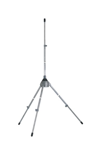
I still think your SWR sucks…
-
Yeah I know, it's shit.No, the monopole on the hockey stick.
So this one?
Do you have a better picture of the actual antenna or is it just a piece of metal sticking upright? Where is the coax shield connected?
You can easily convert it to a groundplane antenna by using 3 or 4 equal length wires connected to the coax shield and pointing down like this:
I still think your SWR sucks…
The copper rod is pressed into the turned nylon bush and the coax center connected below.
I'll turn another step on the nylon bush and connect the braid to some mesh that sits on the step.
Not sure what I have for the mesh and that will entail a rummage around in the morning. I have heaps of 1/4" copper rod but setting ground plane 'fingers' up so they'll withstand the weather is troublesome in my mind.
I think it'll be easier with mesh....I'm sure I have some perforated mesh somewhere as I'd rather not use the 3/4" chicken mesh that I've got plenty of.
I made all this years ago and now with a SVA I have the chance to get it right.
The short length of stainless sitting in the BNC socket works so well as the control cabinet provides the ground plane and it still receives transmissions even though it's in a tin shed. The hockey stick monopole is just LOS from where we send the signal from inside the house.
Thanks for the pointers, I'll sleep on them.
-
One more thing: the angle of the radial(s) should be about 45o for an impedance of 50 Ohm.