Author Topic: Quickly, accurately, repeatably measuring xtal/osc frequency  (Read 80716 times)

0 Members and 5 Guests are viewing this topic.

Offline vk6zgo

  • Super Contributor
  • ***
  • Posts: 8109
  • Country: au
Re: Quickly, accurately, repeatably measuring xtal/osc frequency
« Reply #25 on: January 12, 2024, 02:30:38 pm »
Say I have to measure several dozen 2-pin xtal cans, 4.00 Mhz to 80.00 Mhz. They need to be checked for accuracy. All are hot-swappable in a 5v based DIY driver ckt. (see photo). This works very well.
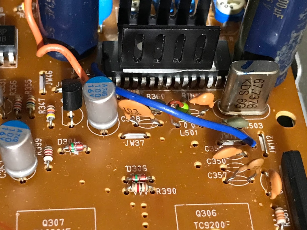
But where I run into weird issues is when the same xtal is in the ckt they are intended to be used. Say an audio D/A, DVD player or CD player. Measurement  in situ , with xtal across an IC's X_in to X_out "driver pins" gives all sorts of distorted or inaccurate readings; perhaps, only the old Tek 465 is most reliable and repeatable for xtals in circuit.
What I have to measure:
I have an old-school but calibrated Tek 465, a modern Siglent 1202x-e dso, NanoVNA, NanaoSA, Owon xdm2041 desktop dmm, and Koolertron DDS sig gen/counter.
Does anyone have preferences?

==================
Test jig:
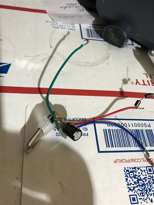

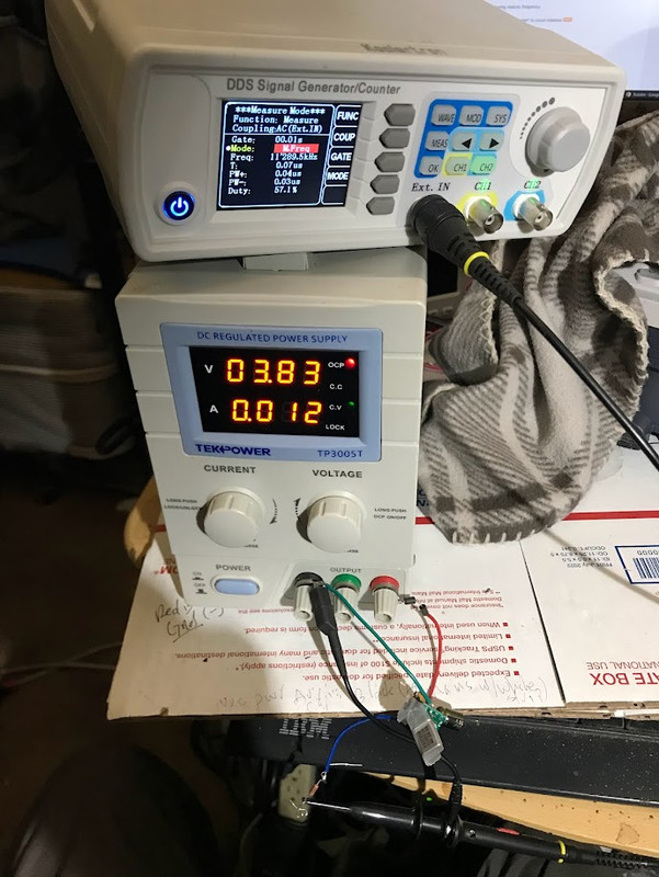
Works well even with simple DDS counter:

But here's where I run into issues (e.g., measuring in circuit, with xtal driven by microprocessor's X_in/X_out pins. I get no or garbage readings when probing at X_in or X_out -- with dso, dds, dmm, NanoSA, etc):
[/url

When using the 465 do you use the "CH1 vert sig out" to feed your frequency counter?

Before my 7613 failed, I found that very convenient with my less than stellar frequency counter, as it provided a controllable gain buffer with built in waveform display----you can't get much better than that!

In most of the crystal oscillator stages I've looked at, I have just placed the 'scope probe in close proximity to the metal body of the crystal package.

There is usually enough pickup, but if it is a bit minimal, I rest the outside of the "witch's hat against the body.
As there is no real direct connection, I often used "x1"probes.
 

Offline whateverTopic starter

  • Contributor
  • !
  • Posts: 45
  • Country: us
Re: Quickly, accurately, repeatably measuring xtal/osc frequency
« Reply #26 on: January 12, 2024, 03:49:43 pm »
All are hot-swappable in a 5v based DIY driver ckt. (see photo). This works very well.
Please share schematics, if it's not a secret. I need to build one too :).

I encourage you to build the Kwack Clock first. Shown in my images.

That said, the easier option is:
Use the schematic in the hsn74vc1gxo4 datasheet.
https://www.ti.com/lit/ds/symlink/sn74lvc1g04.pdf
You'll need a PCB to solder that 6-pinner SOT to. Ali has them.
Add a high-quality 220uF electro cap across the Vcc and GND. Add a ferrite in series with Vcc. Add a high quality R (say 50 ohm) on the signal (out) pin. Use a typical socket (female) connector for 2-pin xtal plug-in. You can use a variable PSU, as shown in my images, to see what effects voltage and current have on the waveform. That PSU also allows one to monitor current drawn at various voltages. 

BTW: the sn74lvc1g04  and mc12060/61 are limited to a max of 28Mhz. There are xtals cut to much higher primary (fundamental) tones than 28mHz. If anyone knows of standalone osc. driver capable of driving. higher Mhz, let us know.
« Last Edit: January 12, 2024, 03:54:41 pm by whatever »
 
The following users thanked this post: shapirus

Offline Andy Chee

  • Super Contributor
  • ***
  • Posts: 2101
  • Country: au
Re: Quickly, accurately, repeatably measuring xtal/osc frequency
« Reply #27 on: January 12, 2024, 03:54:27 pm »
If anyone know of standalone osc. driver capable of driving. higher Mhz, let us know.
How about 200MHz?

https://www.digikey.com.au/en/products/detail/crystek-corporation/CCO-083-200-000/1643961
 

Offline whateverTopic starter

  • Contributor
  • !
  • Posts: 45
  • Country: us
Re: Quickly, accurately, repeatably measuring xtal/osc frequency
« Reply #28 on: January 12, 2024, 04:02:45 pm »
If anyone know of standalone osc. driver capable of driving. higher Mhz, let us know.
How about 200MHz?

https://www.digikey.com.au/en/products/detail/crystek-corporation/CCO-083-200-000/1643961
Huh????
That ain't no  standalone osc. driver.
 

Offline Andy Chee

  • Super Contributor
  • ***
  • Posts: 2101
  • Country: au
Re: Quickly, accurately, repeatably measuring xtal/osc frequency
« Reply #29 on: January 12, 2024, 04:09:04 pm »
If anyone know of standalone osc. driver capable of driving. higher Mhz, let us know.
How about 200MHz?

https://www.digikey.com.au/en/products/detail/crystek-corporation/CCO-083-200-000/1643961
Huh????
That ain't no  standalone osc. driver.
The driver is inside the can with the crystal.
 

Offline shapirus

  • Super Contributor
  • ***
  • Posts: 2254
  • Country: ua
Re: Quickly, accurately, repeatably measuring xtal/osc frequency
« Reply #30 on: January 12, 2024, 04:39:13 pm »
Use the schematic in the hsn74vc1gxo4 datasheet.
https://www.ti.com/lit/ds/symlink/sn74lvc1g04.pdf
You'll need a PCB to solder that 6-pinner SOT to. Ali has them.
Add a high-quality 220uF electro cap across the Vcc and GND. Add a ferrite in series with Vcc. Add a high quality R (say 50 ohm) on the signal (out) pin. Use a typical socket (female) connector for 2-pin xtal plug-in. You can use a variable PSU, as shown in my images, to see what effects voltage and current have on the waveform. That PSU also allows one to monitor current drawn at various voltages. 
Well there's no oscillator circuit in that datasheet, but as far as I understand, and from what I can see in your photos, it appears to be the classic Pierce oscillator (https://en.wikipedia.org/wiki/Pierce_oscillator).

The PCB, VCC decoupling and output resistors are all trivial things, but what I'm curious about, if it's indeed the Pierce oscillator, is what values did you use for the feedback resistor and for the two load capacitors to make this work well over a wide range of the crystals' resonanant frequencies.
 

Offline Kim Christensen

  • Super Contributor
  • ***
  • Posts: 1819
  • Country: ca
Re: Quickly, accurately, repeatably measuring xtal/osc frequency
« Reply #31 on: January 12, 2024, 04:44:36 pm »
Huh????
That ain't no  standalone osc. driver.

Look at the datasheet. Here's one that's similar
Notice the name "High Frequency SineWave Crystal Oscillator", and the fact that they spec power supply voltage and current draw among other things. There's an oscillator and buffer amplifier, inside that can, in addition to the crystal.
 

Offline whateverTopic starter

  • Contributor
  • !
  • Posts: 45
  • Country: us
Re: Quickly, accurately, repeatably measuring xtal/osc frequency
« Reply #32 on: January 12, 2024, 06:42:05 pm »
Use the schematic in the hsn74vc1gxo4 datasheet.
https://www.ti.com/lit/ds/symlink/sn74lvc1g04.pdf
You'll need a PCB to solder that 6-pinner SOT to. Ali has them.
Add a high-quality 220uF electro cap across the Vcc and GND. Add a ferrite in series with Vcc. Add a high quality R (say 50 ohm) on the signal (out) pin. Use a typical socket (female) connector for 2-pin xtal plug-in. You can use a variable PSU, as shown in my images, to see what effects voltage and current have on the waveform. That PSU also allows one to monitor current drawn at various voltages. 
Well there's no oscillator circuit in that datasheet, but as far as I understand, and from what I can see in your photos, it appears to be the classic Pierce oscillator (https://en.wikipedia.org/wiki/Pierce_oscillator).

The PCB, VCC decoupling and output resistors are all trivial things, but what I'm curious about, if it's indeed the Pierce oscillator, is what values did you use for the feedback resistor and for the two load capacitors to make this work well over a wide range of the crystals' resonanant frequencies.
You're right.My bad!!
Those TI part numbers are so similar.
SN74LVC1GX04 Crystal Oscillator Driver
Here you go:
https://www.ti.com/lit/ds/symlink/sn74lvc1gx04.pdf
 
The following users thanked this post: shapirus

Offline whateverTopic starter

  • Contributor
  • !
  • Posts: 45
  • Country: us
Re: Quickly, accurately, repeatably measuring xtal/osc frequency
« Reply #33 on: January 12, 2024, 06:49:56 pm »
Huh????
That ain't no  standalone osc. driver.

Look at the datasheet. Here's one that's similar
Notice the name "High Frequency SineWave Crystal Oscillator", and the fact that they spec power supply voltage and current draw among other things. There's an oscillator and buffer amplifier, inside that can, in addition to the crystal.
Again, this is not a driver!
What some could have suggested was what Dave dug up in that video.
It is  that NPC driver[ https://pdf1.alldatasheet.com/datasheet-pdf/view/7681/NPC/613N1.html that is inside the one of those 4-pin oscillator cans.

https://youtu.be/dkdLWronrlk?t=364

https://youtu.be/fZYtdE2AF6g
« Last Edit: January 12, 2024, 06:52:20 pm by whatever »
 

Offline Andy Chee

  • Super Contributor
  • ***
  • Posts: 2101
  • Country: au
Re: Quickly, accurately, repeatably measuring xtal/osc frequency
« Reply #34 on: January 12, 2024, 07:00:34 pm »
Huh????
That ain't no  standalone osc. driver.

Look at the datasheet. Here's one that's similar
Notice the name "High Frequency SineWave Crystal Oscillator", and the fact that they spec power supply voltage and current draw among other things. There's an oscillator and buffer amplifier, inside that can, in addition to the crystal.
Again, this is not a driver!
What some could have suggested was what Dave dug up in that video.
It is  that NPC driver[ https://pdf1.alldatasheet.com/datasheet-pdf/view/7681/NPC/613N1.html that is inside the one of those 4-pin oscillator cans.
What's wrong with the 613N1?  According to the datasheet it operates up to 50MHz.  And the 200MHz crystal oscillator will have a faster driver again.
 

Offline Kim Christensen

  • Super Contributor
  • ***
  • Posts: 1819
  • Country: ca
Re: Quickly, accurately, repeatably measuring xtal/osc frequency
« Reply #35 on: January 12, 2024, 07:26:20 pm »
Huh????
That ain't no  standalone osc. driver.

Look at the datasheet. Here's one that's similar
Notice the name "High Frequency SineWave Crystal Oscillator", and the fact that they spec power supply voltage and current draw among other things. There's an oscillator and buffer amplifier, inside that can, in addition to the crystal.
Again, this is not a driver!
What some could have suggested was what Dave dug up in that video.
It is  that NPC driver[ https://pdf1.alldatasheet.com/datasheet-pdf/view/7681/NPC/613N1.html that is inside the one of those 4-pin oscillator cans.

https://youtu.be/dkdLWronrlk?t=364

https://youtu.be/fZYtdE2AF6g

I think you are confused. Buffer... Driver... Whatever. Generally it's an amplifier that follows the oscillator which prevents the load from effecting the oscillator. Either a buffer or driver will work. A buffer is usually an amplifier with a gain of one and a driver is an amplifier with a gain greater than one. Both are amplifiers stages. Maybe I'm confused by what you're after or are trying to say.
Nowhere on the NPC SM5613 datasheet is the word "driver" mentioned. They use the term "output buffer" and the only thing mentioned is TTL/CMOS drivability...


Share me

Digg  Facebook  SlashDot  Delicious  Technorati  Twitter  Google  Yahoo
Smf


-->