I’m not seeing it. How does driving a diode from a current source (practically) eliminate the forward voltage drop?
Sure, I understand how more and more amplification of a low level input signal makes the forward drop and non-linearity of a diode's turn-on point become less and significant at the output of that amplifier...I just built one of those types of RF level meters--but I don't think that is what the author is describing here--not exactly.
Rob
Can anyone dumb this down for me?
From The Art of Electronics, second edition:
“Current-source drive Amplitude-tracking detector
Another solution to the problem of rectifier
diode nonlinearity is to drive the rectifier circuit
with a current, rather than a voltage;
the output is then loaded resistively, to produce
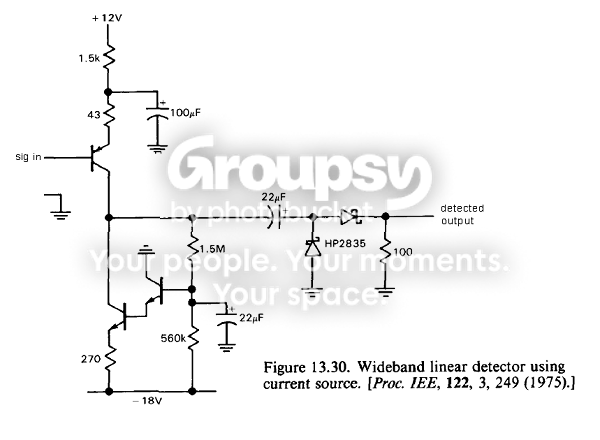
a proportional output voltage (Fig. 13.29). Figure 13.30 shows a good
implementation with voltage-controlled
transistor current source; the performance
is shown in Figure 13.3 1. You can understand
this circuit in another way: With
no input signal, the amplifier's output is
decoupled from the rectifier network, producing
very high voltage gain (with its
current-sink load); thus, only a very small
input signal is needed to turn on the diodes.
At that point the voltage gain drops to
Gv = &/(RE + re) (in this case, Gv x
3), preventing saturation. With a wideband
amplifier and fast diodes, this circuit
design will operate to 100 MHz or more.”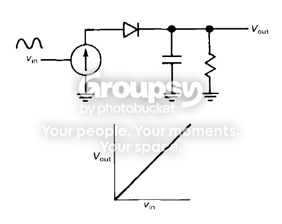

 Home
 Help
 Search
 Login
 Register


