Some news in the optical field:
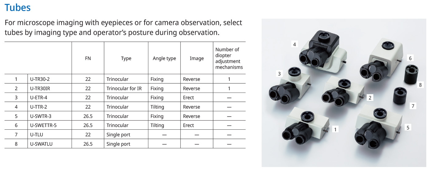
This overview from an Olympus brochure for the BX53M/BXFM microscope family shows a selection of the options that can be used for observing objects. Trinocular heads that can operate two eyepieces and a camera are common. With some variants, the angle at which the eyepieces are positioned can be adjusted for more ergonomic operation. There is also a special variant for infrared microscopy. If the eyepieces are not required or if space is limited, slim cylinders containing only a tubelens can be used. Both trinocular heads and tubelenses are available in versions with an image circle of 22mm and versions with an image circle of 26,5mm. A single digit at the end of the designation indicates the revision.
In principle, all trinocular heads and tube lenses can be used with all microscopes in the BX family. Olympus does not explicitly exclude any variants. However, it has been found that the image quality varies considerably.
The U-TR30-2 head is widely used. In some cases, its predecessor, the U-TR30, which is painted black, can still be found. Although the U-TR30-2 is only specified for an image circle of 22mm, it can be used with an APS-C sensor. The outer areas of the image are not perfectly reproduced, but it can be used to create panoramas. Focus stacking further improves the quality.
Unfortunately, the options specified for a 26,5mm image circle are very expensive. Surprisingly, the more complex U-SWETTR-2 model is sometimes cheaper to find. Unlike the U-SWTR, the U-SWETTR allows you to adjust how steeply the eyepieces point upwards.
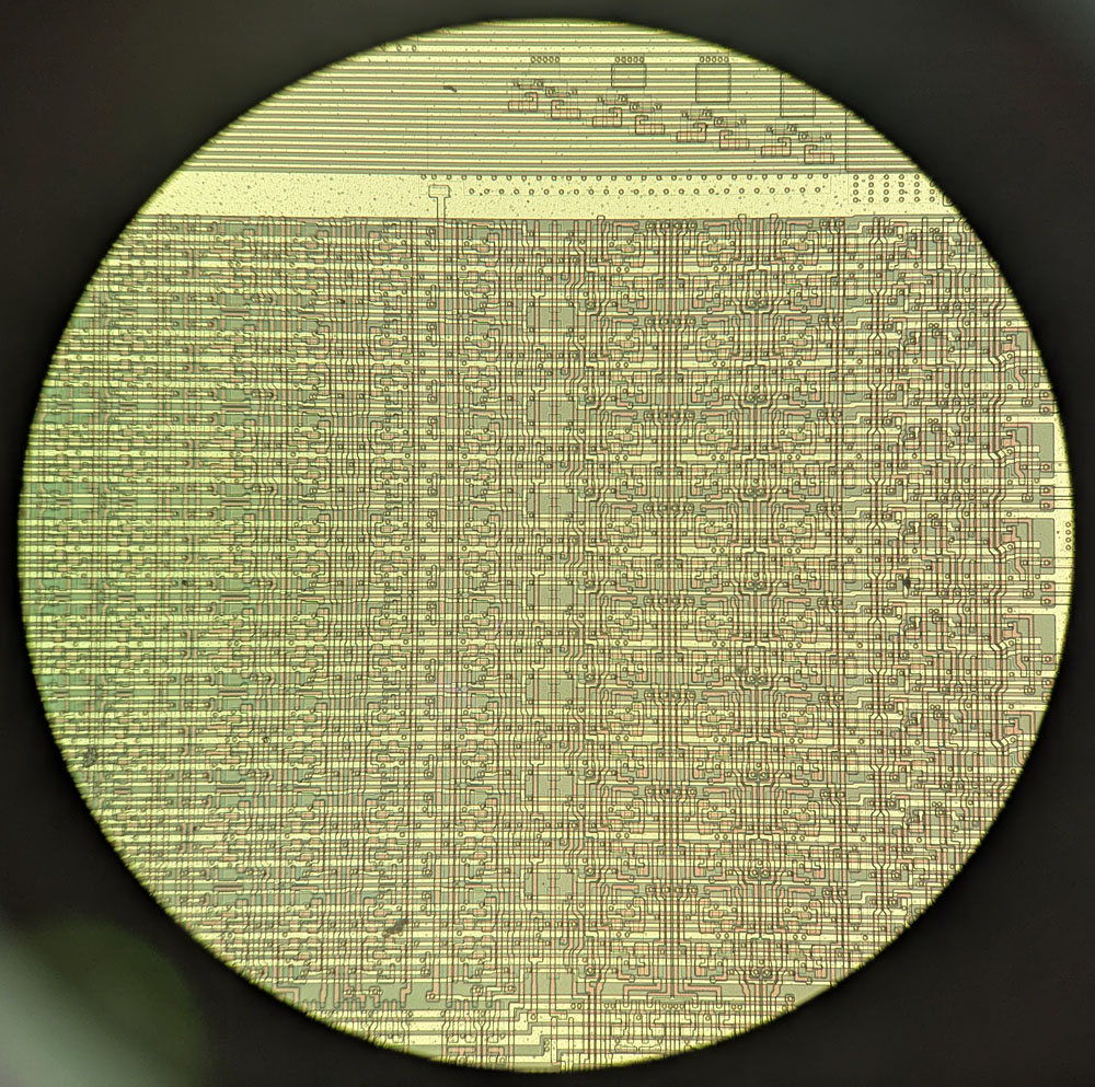
The view through a 26,5mm eyepiece is impressive.
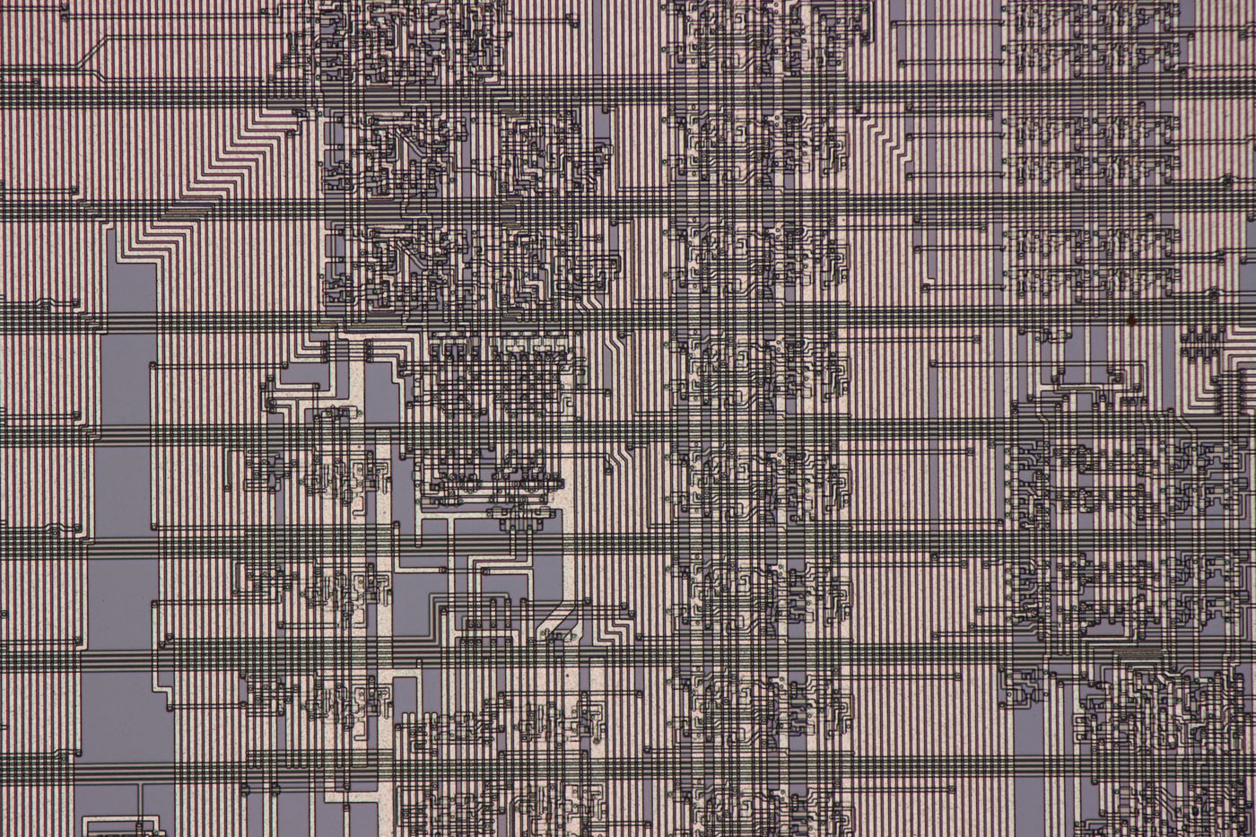
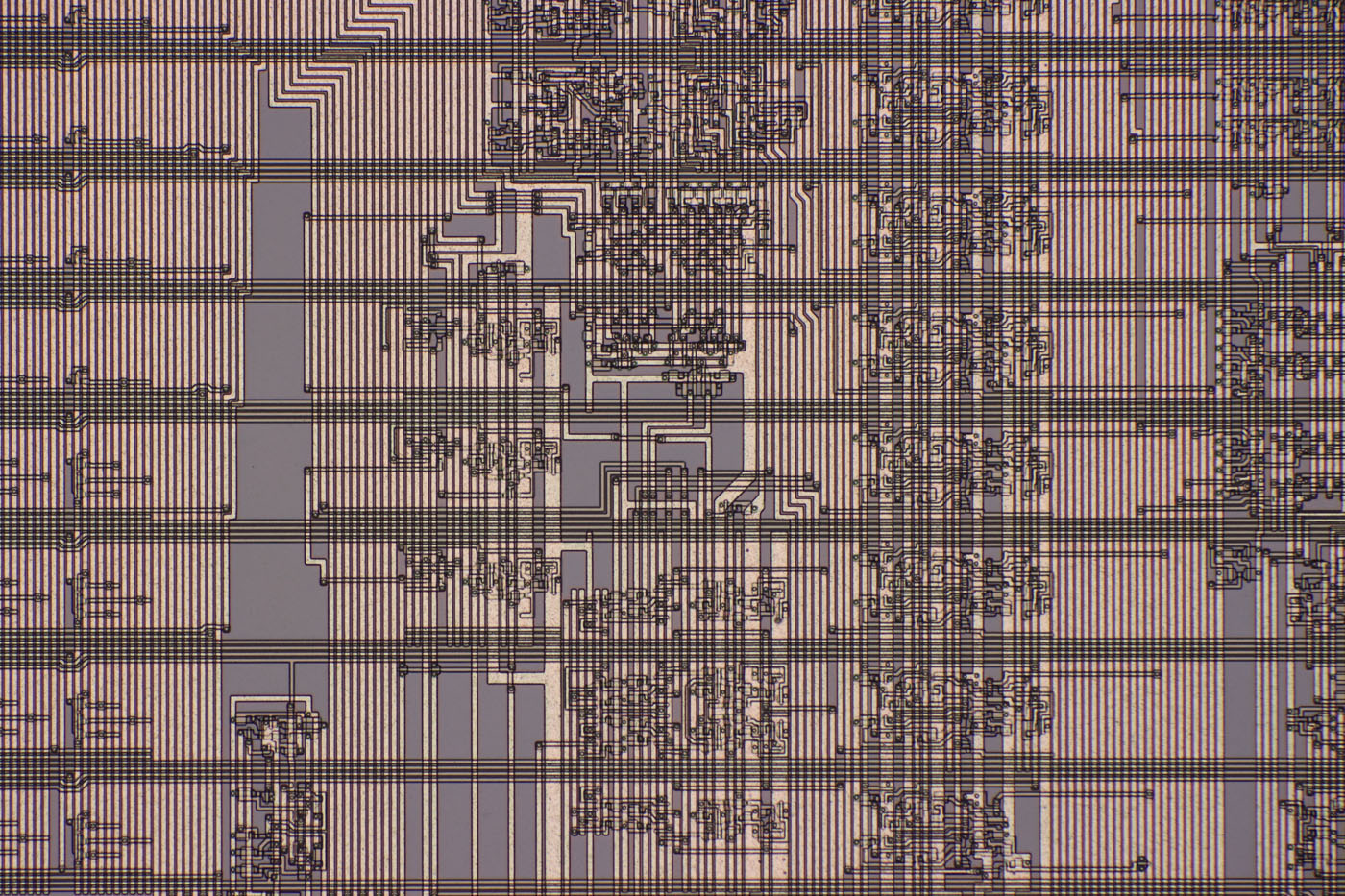
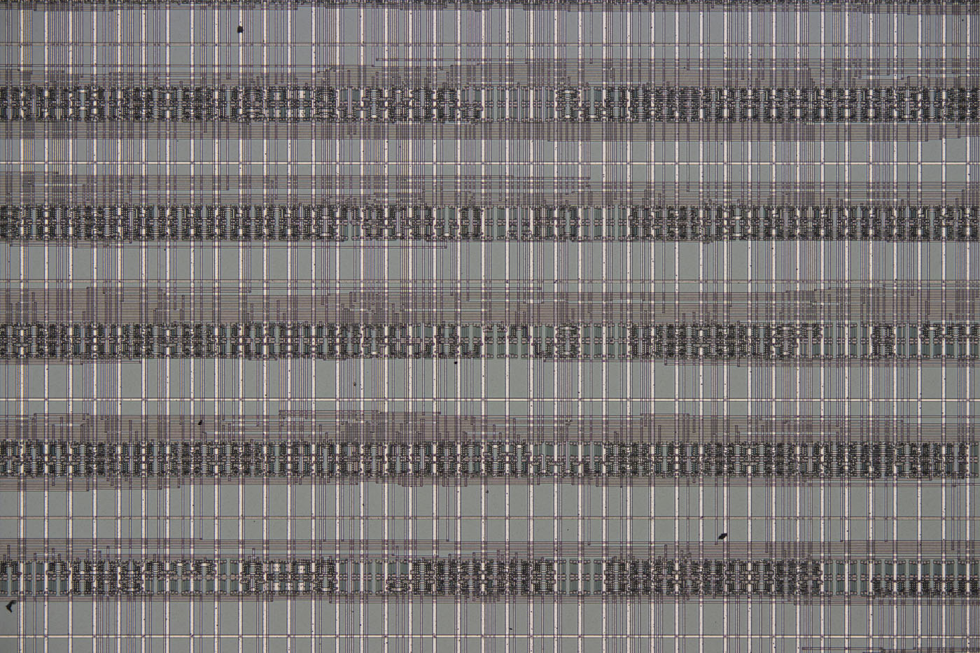
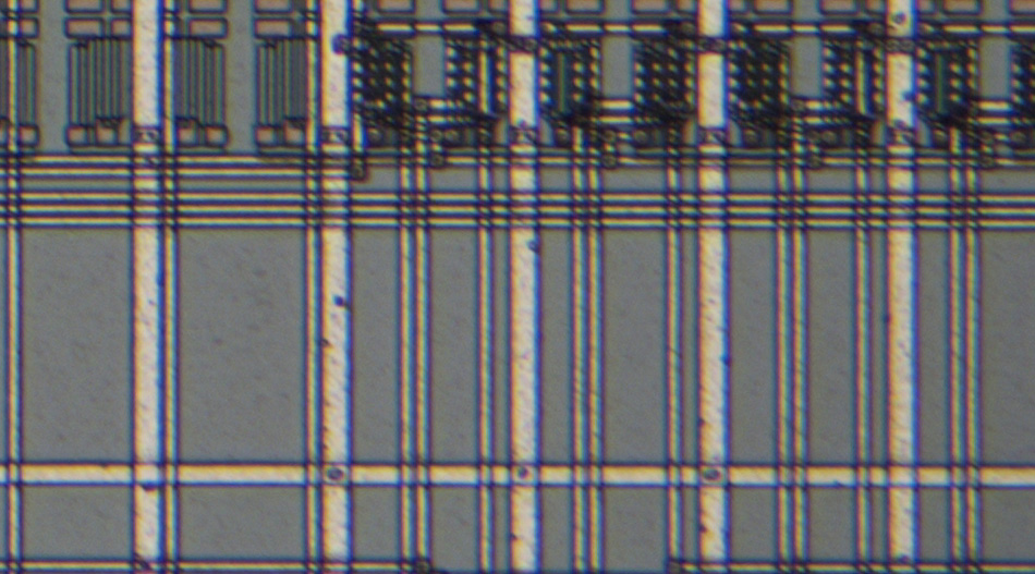
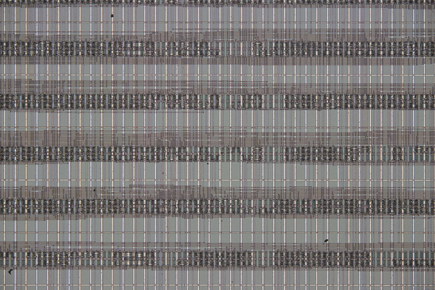
The upper of these two images was taken with the U-TR30-2. The lower image was taken with the U-SWETTR-2. In both cases, the UIS2 objective MPLAN FL N 20x was used. These are unprocessed single images without focus stacking. The depth of field of the MPLAN FL N 20x is actually too shallow to take pictures without focus stacking. This explains the slight blurring on one side. Sharp areas were selected for further examination.
Both images are also available in higher resolution:
https://www.richis-lab.de/images/howto/17x04XL.jpg (10MB)
https://www.richis-lab.de/images/howto/17x05XL.jpg (10MB)
The image above is taken from one corner of the image captured with the U-TR30-2. The image quality is poorest in the corners. A slight loss of sharpness can be seen. There is also some chromatic aberration. However, as described, this image quality is perfectly acceptable for working with. Panoramas can also be created. Only occasionally do the interfaces between the individual images produce artifacts.
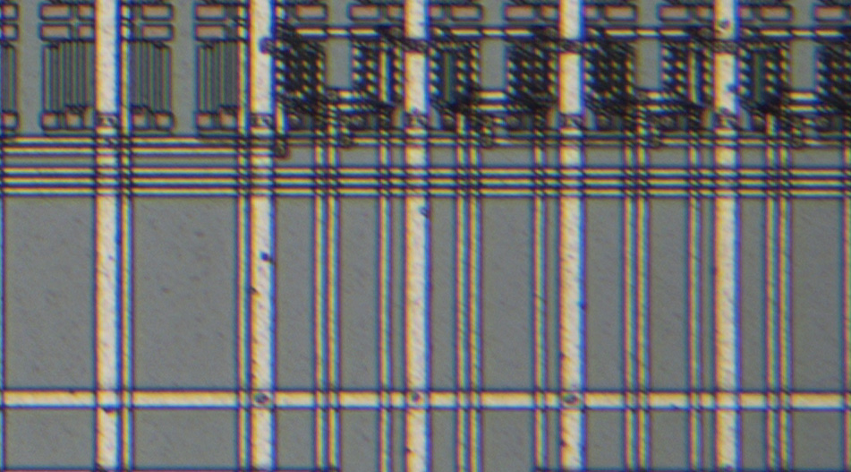
Surprisingly, the image quality of the U-SWETTR-2 is hardly any better. It is assumed that the additional degree of freedom of the eyepieces comes at the expense of image quality. Perhaps this is why there is now a fifth revision of the U-SWETTR.
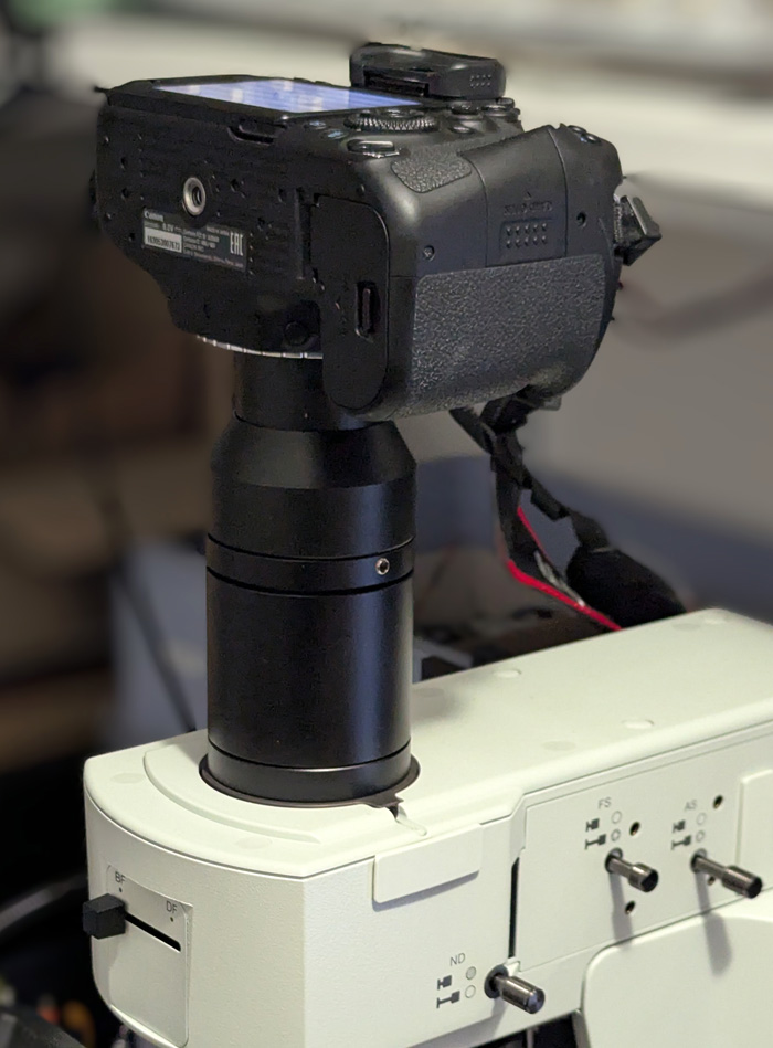
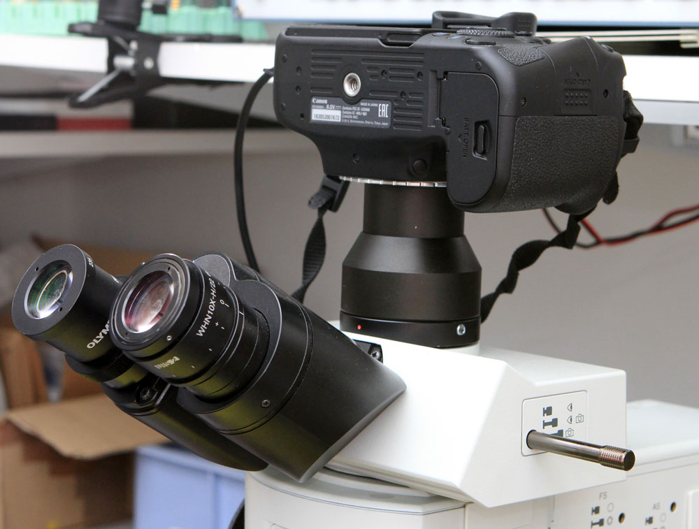
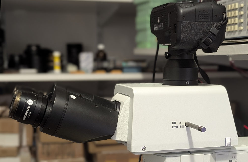
The U-SWATLU tubelens replaces the trinocular head and is a relatively inexpensive way to make optimal use of the 26,5mm image circle.
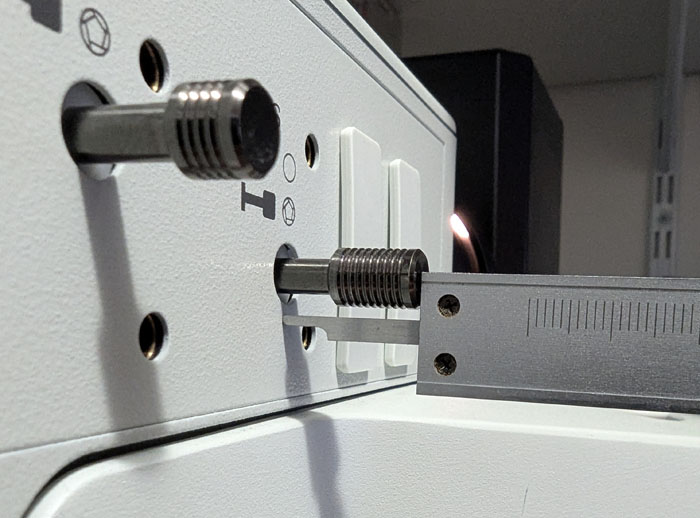
Without the trinocular head, it is no longer possible to view the image directly. Furthermore, it is no longer possible to remove an eyepiece in order to adjust the aperture diaphragm of the Köhler illumination. You have to note down the position of the aperture lever for the different objectives so that you can then make the adjustment blindly. It is advisable to use a caliper for this.
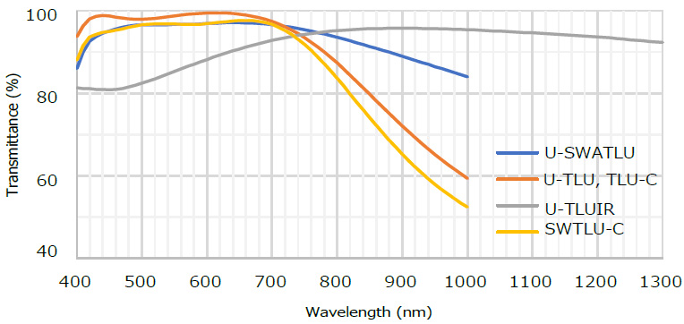
In addition to the larger image circle, the U-SWATLU tubelens has another advantage. It allows more light in the near-infrared range to pass through. This is a major advantage when performing infrared microscopy.
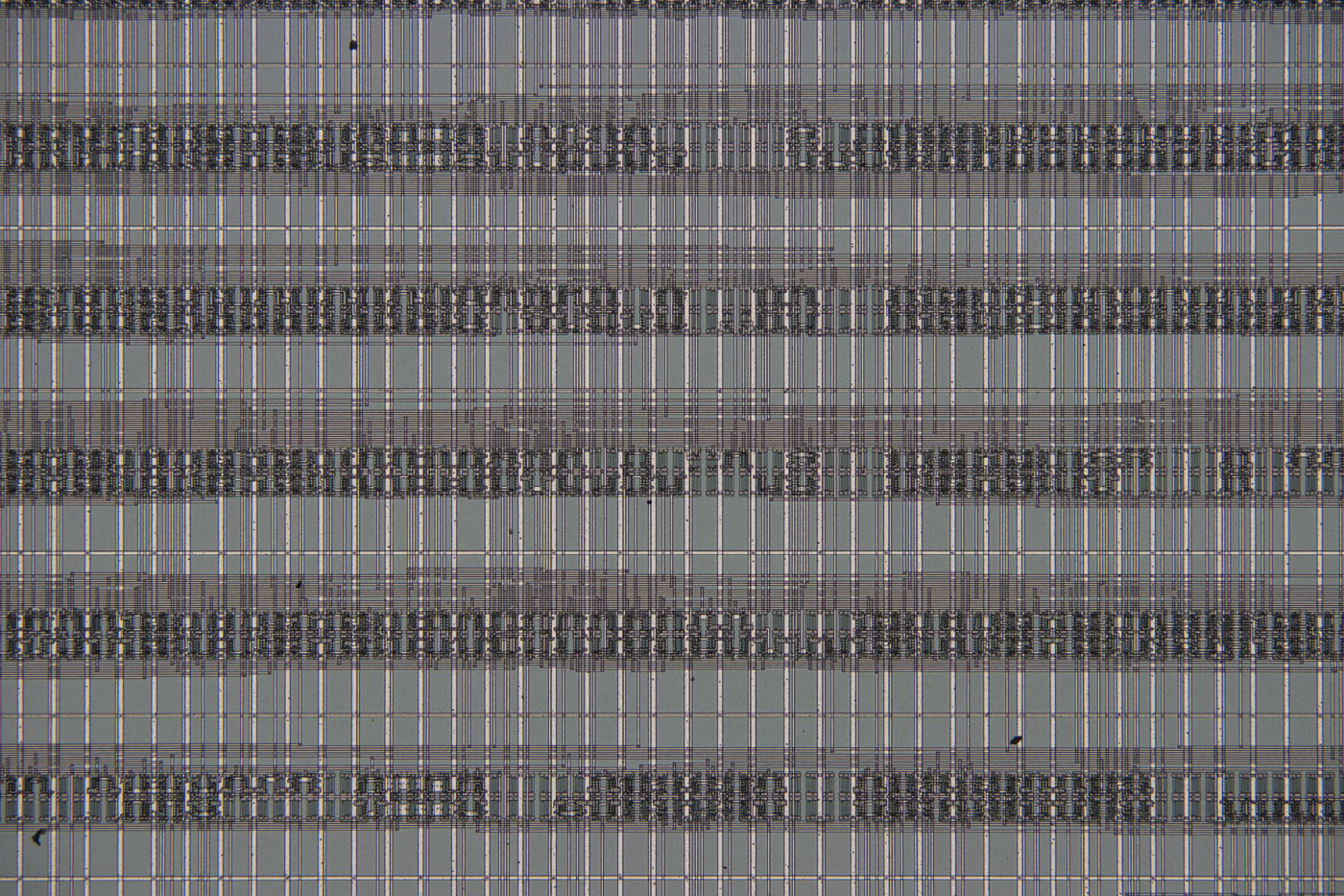
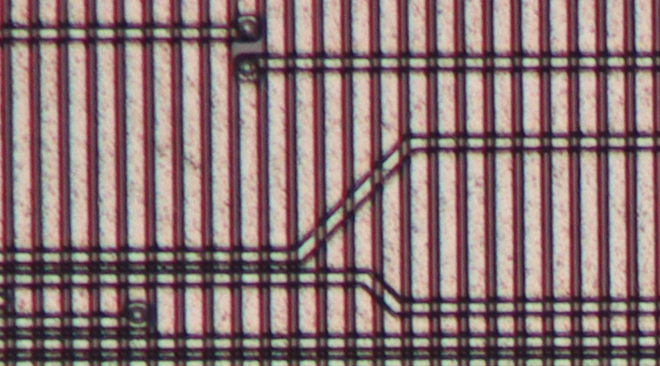
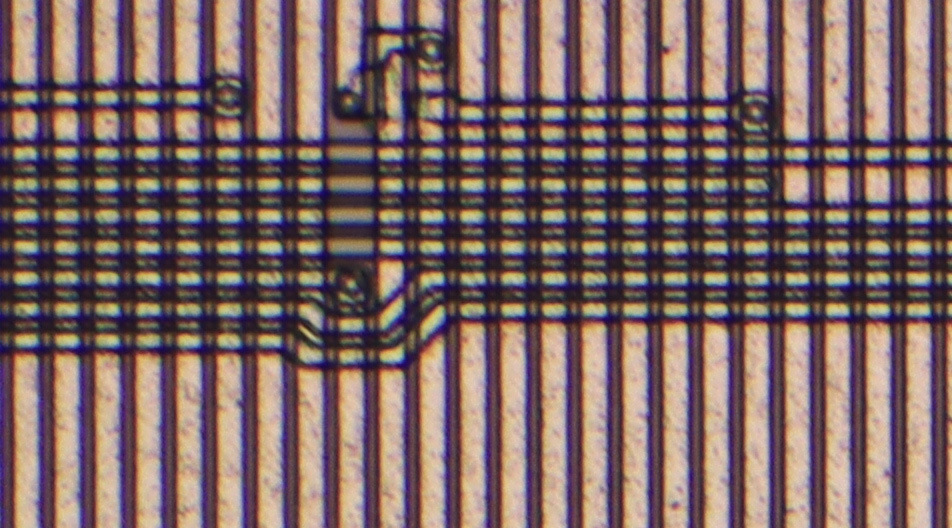
The UIS2 objective MPLAN FL N 10x was used to take these images. The upper image was taken with the U-TR30-2, and the lower image with the U-SWATLU.
Both images are also available in higher resolution:
https://www.richis-lab.de/images/howto/17x10XL.jpg (12MB)
https://www.richis-lab.de/images/howto/17x11XL.jpg (11MB)
As with the 20x lens, a certain amount of blurring can be seen with the U-TR30-2. Chromatic aberration is also evident again.

The U-SWATLU tubelens significantly improves image quality. The image is sharper and almost free of chromatic aberration. The last remaining color fringes are only visible at very high zoom factors.

These two test images were taken with the UIS objective MPLAN FL 10x. The upper image was taken with the U-TR30-2 head, while the lower image was taken with the U-SWATLU tube lens.
Both images are also available in higher resolution:
https://www.richis-lab.de/images/howto/17x14XL.jpg (12MB)
https://www.richis-lab.de/images/howto/17x15XL.jpg (12MB)
The UIS and UIS2 objectives are comparable. With the U-TR30-2 head, blurring and chromatic aberration are equally apparent.
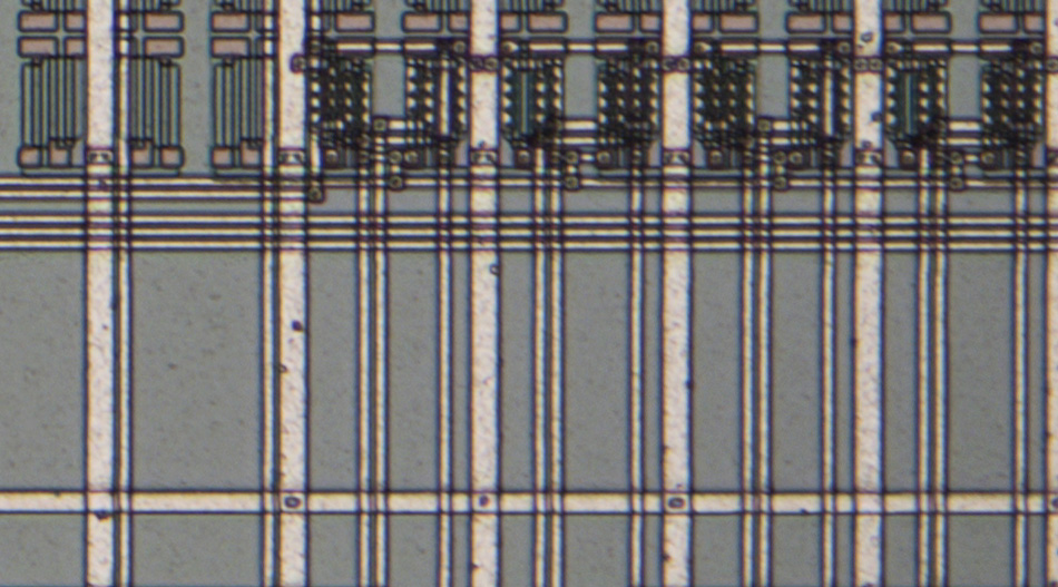
The U-SWATLU tubelens also significantly improves image quality in terms of sharpness and chromatic aberration. In contrast to the UIS2 objective, however, the UIS objective retains slightly more chromatic aberration.
https://www.richis-lab.de/Howto_Microscope_Tubelens.htm 


