Nice! That looks familiar, think I've looked through that before - it's definitely striking, the difference between general aviation stuff (where half could very well have been put together by one person in a garage) and commercial aviation stuff.
Smiths Remote Interface UnitHere's a more modern one, from 2004, made by Smiths Aerospace.


My impression was that a "remote interface unit" was kind of like an I/O expander for an aircraft, and that seems to be born out by the internals. Let's take a look:


There's a smaller control daughterboard, stuck on top of the main board. Here's what the main board looks like, with the control board removed:


Off in one corner is the local power supply, with a UC2843 PWM controller, and a couple transformers and/or coupled inductors, which probably provide the low-voltage power for the onboard digital logic and analog:

The large black box towards the upper left is a capacitor (probably for buffering the input power rail). The transistor (SOT-223 package) at the very bottom edge, below one of the magnetics, is probably the switching transistor. The many diodes above the magnetics are probably the rectifiers for multiple low-voltage outputs.
Near one connector is what looks like a lot of switched-power outputs, with power transistors and 0.27Ω resistors for current sensing. Not sure what the chips with the white labels on them are...maybe isolators of some kind? (if the "power-output ground" is different from the "control ground") Or over-current protection / current-sense amps / gate drivers (if fast switching is needed for PWMing any of the power outputs) / all of the above?
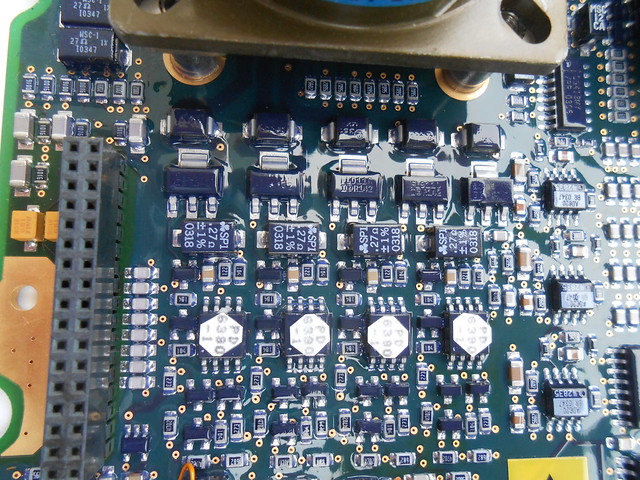
If you look back at the power supply photo above, there's an analog mux ("HI9P548-9") between these power outputs and the power supply, which is probably used for selecting between the different output-current-sense signals, to measure one at a time.
There's possibly one more output channel just around the corner, plus some filtering (series inductor, white box) and protection (TVS diode(s) for over-voltage) for the power input:

...and possibly a couple more output channels in between the two connectors, although the current sense resistor looks different and one channel doesn't have a current sense resistor visible at all:

The other connector looks like it's all inputs. There's a lot of series 56KΩ resistors, leading into dual diodes in SOT-23 packages, to clamp the input signal between the rails -
see here for how this is probably arranged (I'm not 100% sure about these being dual diodes, but would bet a lot of money that's the case). Between the large series resistance for current-limiting, and the clamping diodes, this serves to protect any input circuitry from the "wild west" situation that's happening on the aircraft wiring: lightning strikes, accidental shorts to high-voltage power, long wiring picking up high-power radar transmissions, etc.

The rows of many ceramic caps at the bottom of this photo are probably providing some basic filtering on these inputs. The inputs seem to feed into a large group of analog muxes nearby (DG4xx series), which probably are cascaded in a tree-like configuration to select only one of these inputs at a time.

From counting the SOT-23 packages, I think there's roughly 43 external inputs, which requires a whole lot of muxing over a few hierarchical layers. The 3x AD620 instrumentation amplifiers near the middle of the board (visible in some earlier photos) are probably providing some differential inputs, as a complement to all the single-ended analog inputs here.
There's also a bit of mystery analog circuitry around the side: maybe an output? There's a DG413 (4x SPST analog switch), LM2903 (dual comparator), and 2x ST
TS512AI dual precision op-amps. There's also some colorful resistors which look similar to precision types from Vishay and KOA Speer I've used before.

This section might be scaling down a few higher voltages, buffering them, muxing between them with the analog switches, and then doing some kind of window-comparator function to check that they're within normal range (monitoring power supplies, for example). Or who knows really, there's a thick layer of conformal coating over everything and most of the traces are on inner layers.
Ok, now that we've seen the switched (open-drain?) power outputs and muxed analog inputs on the main board, let's take a look at the control board. What stands out most here is the pair of microcontrollers:
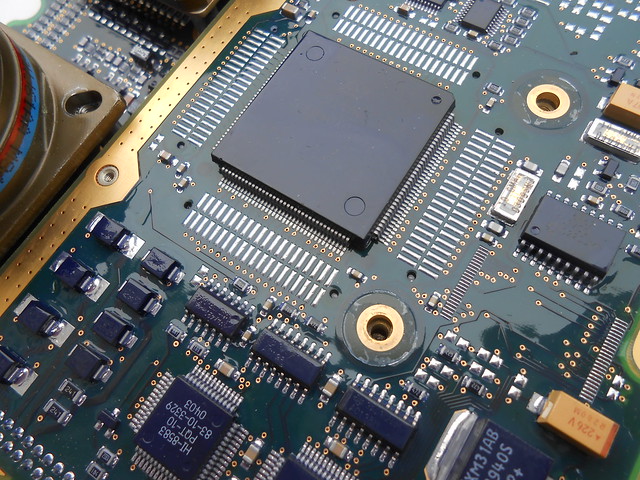
The large one is an ST10F269Z2Q3, a
reasonably-powerful 16-bit part with some multiply-accumulate accelerators for signal processing(!!!) and a whole bunch of peripherals (PWM, ADC, timers, serial interfaces, an RTC, etc.). The small one is a much smaller 8-bit PIC16F627. I have no idea what the division of labor is between these two.
To one side are some local linear regulators, and two
HI-8583s, which are dual ARINC 429 transceivers. ARINC 429 is a commonly-used 2-wire serial bus on commercial aircraft, with similar use cases to MIL-STD-1553. These transceivers include not just the level-shifting circuitry, but the serial encoding/decoding and FIFOs for storing received messages (or holding onto messages to transmit): they're meant to interface through a 16-bit processor bus, which is where the "external bus interface" of the ST10F269 probably comes in handy.

Covering the rest of the control board is an analog section (with many probable-op-amps and precision resistors, for proper scaling and offsets) leading into an
AD977A 16-bit 200 ksps ADC. This is probably what's reading all those external inputs one at a time, through the tree of analog muxes. Even though the ST10F269 has an onboard ADC, the integrated ones are (intentionally) never going to be as good as a dedicated-purpose separate ADC, whether because of on-chip noise, IC process optimized for high-density digital instead of for high-performance analog, limited die area, lack of trimming, not wanting to sink money into an expensive high-quality ADC that many customers may never use on the general-purpose MCU, etc. etc. I'm guessing the high sampling rate (impressive to maintain 16 bit resolution at 200 ksps!) is useful here when scanning between so many different inputs, if it needs to sample each individual input frequently.


So overall, this really does seem like the aircraft version of an I/O expander. It's got serial interfaces to talk to higher-level computers on the plane, which can then tell it to turn on or off some outputs, and read back input values; probably offload some I/O processing as well. The main MCU being so over-qualified for doing only basic communications and I/O suggests that it's also using its math capabilities to do some filtering or feedback loops or something similar. This particular unit, being sold as surplus, supposedly came from a British Lynx helicopter. Anyways, hope you enjoyed the photos.


