Good point, that would make a lot of sense.
Ok, here's one that's not strictly avionics, but let's make an exception and call it "high-reliability vehicle electronics":
Raytheon boards from submarine communications terminalThese are two boards which, based on the National Stock Number info, seemed to come from the AN/USC-38 satellite-comms terminal, used on submarines (the Trident in particular is called out in the description) and date back to roughly the late 80's. There's more info on the overall system here:
https://www.globalsecurity.org/space/library/report/1999/nssrm/initiatives/anusc38.htmIt used EHF-range (> 30 Ghz typically) frequencies, so I assume this could only be done when a sub had surfaced, as opposed to the
amazingly low frequencies & massive antennas used in other cases to reach submarines underwater. Data rate was still low, at 2.4 kbps max.
HV Monitoring board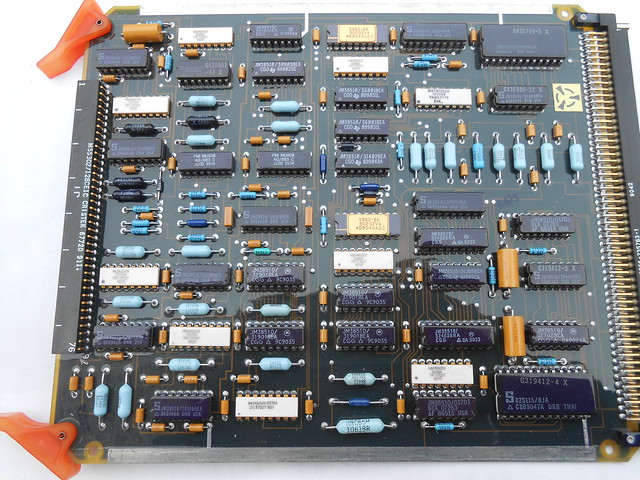

Transmission of any real power at 30 Ghz+, especially at the time, would be very much non-solid-state: something along the lines of a
Klystron or
Traveling Wave Tube. These use high voltages to accelerate a beam of electrons in a vacuum, and so this board (based on the label) seems to be about monitoring these high voltages for the control system.
/?action=dlattach;attach=2181115;image) Analog section
Analog sectionAt the left, there's a bunch of quad op-amps. These probably take the different voltages from the various HV monitoring points (pre-scaled down to something reasonable by external voltage dividers) and buffer/scale/offset them to feed to the ADCs on this board.
That 2nd connector isn't for external connections: the various I/O all happens through the backplane. This is a debug/testing connector so that you can look at internal signals, and narrow down a fault to a particular card while still installed and working, without having to power down the whole system and use an
extender card, as is common with test equipment from the same era. You can see the same thing on some other avionics PCBs I've looked at:
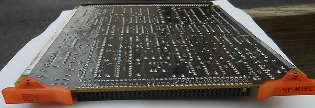
(Right side, between the release levers)
(Gold fingers along the top edge, again between the release levers)

(Row of discrete testpoints)
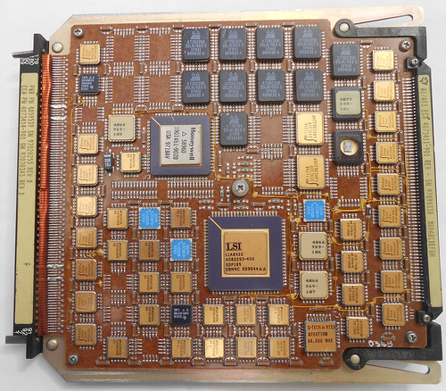
/?action=dlattach;attach=2181121;image)
This is the kind of equipment where you need to be able to swap in replacement boards, and can't just write off the entire extremely-expensive comms terminal with a "we'll fix it later" when you're in the field (at sea).
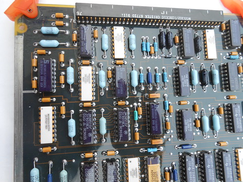
Anyways...the analog input channels go through the two MUX08 analog muxes, and into the two ADCs:
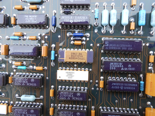

This is marked "AD9040A", but the AD9040A is actually a newer Analog Devices part with many more pins, and an unnecessarily-high sample rate (40 Msps) for this application. This seems to be a case of accidental part number re-use, because looking up the military part number "5962-8680202VA" shows that
the equivalent Analog Devices part is actually the
10-bit AD571, which has the correct number of pins and a more reasonable sampling rate (25 ksps) for this application.
The 54LS221 dual one-shot ("monostable") timers nearby are probably used to generate some of the "start conversion" pulse timing.
ADC input sourcesThe two MUX08 analog muxes, which select the ADC input channels, seem to have their control inputs ganged together. These control inputs can be selected from one of two "channel selection modes" by the 54LS157 4x 2:1 digital muxes near the top-left corner. One of these channel selection modes comes from the two 54LS148 8-input priority encoders closer to the middle of the board. I'd originally assumed that these priority encoders were used to generate interrupts based on input-out-of-range signals from analog comparators, but the selection inputs actually go to the backplane connector: so I think these priority encoder chips might be used for some kind of "one-hot" channel selection scheme, for the software to pick which channel to read.
(Disclaimer: I wasn't able to figure out a full schematic for this board due to multiple layers, traces running underneath top-side ICs, heavy conformal coating, limited time, etc. so these are just my best guesses based on a limited amount of connection tracing)
ADC output dataThe bottom ADC has its output data go directly to the data bus pins on the connector, which connect back to the CPU. The top ADC, however, is a little different. Its 10-bit output instead gets latched by the '377 8x D-FF and '74 2x D-FF chips nearby, and then fed into the address pins of the two PROMs at the top-right of the board (82S131 & 82S181). The PROMs' output data then gets fed to the backplane connector, to be used somewhere else.
So what this looks like, is that the bottom ADC's data is getting used directly, but the top ADC's data is being fed through some kind of programmed lookup table. These two PROMs take in the 10-bit ADC data and produce a 12-bit output, with the top 4 bits coming from the 82S131 (which has access to all the ADC data except the least-significant bit, hence the 512 instead of 1024 addresses) and the bottom 8 bits coming from the 82S181.
I doubt this lookup table is used for calibration alone: a simple pair of gain and offset trimmers would correct for everything except step-to-step non-linearities of the ADC (
DNL), and a lookup table + precision calibration procedure seems like overkill vs. just getting a slightly more expensive ADC with a couple more bits. Instead, it might be used to implement some kind of digital transfer function, either to avoid complicated math in software, or maybe to correct for a non-linear transfer function in the measurement circuits themselves used to meter the high voltages?
RegistersThere's also 4x 54LS670 4x4 register file ICs near the bottom-middle; from tracing the connections, these use the 2x 54LS244 buffers to their left to either read or write from the common CPU data bus. These are arranged as 8 registers of 8 bits each. I wasn't able to follow the address inputs, so I don't know for sure, but it doesn't make sense to just randomly drop some extra registers onto this board unrelated to the rest of the circuitry: my best guess is that the addressing for these is the same 3 bits that set the ADC channel, and so that these work as per-channel configuration registers for some ADC settings (such as the bipolar-vs-unipolar input setting).
Bottom-right PROMsThe two PROMs in the bottom-right corner of the board (82S115 & 82S131) are more of a mystery. At first I assumed these were implementing an ADC data lookup table like the ones in the top-right, but the connections didn't support this. Instead, these share address bits and so create a 512 x 12 memory, where the data outputs are latched by nearby D-FFs and then go to the backplane connector to be used somewhere else. The top bit of the address is latched from a backplane input in a nearby 5474, and so is probably set either by software or by a system on a different card. The lower 8 bits of the addresses come from the adjacent 54LS293 dual 4-bit counter, which is wired to work as a single 8-bit counter. Its clock comes from another mystery external signal on the backplane connector.
So overall, these create 2 separate 256 x 12 lookup tables. External inputs select which of the two tables to use (through the MSB), and external inputs also control the counting through the 256 table entries. This could be some kind of digital waveform generation, but I really have no idea. It's presumably somehow related to the high-voltage monitoring functions of the rest of the card, but also doesn't seem to interconnect with the other circuitry in any way.
Mystery PROMI was struck by the sheer number of PROMs on what should mostly be an analog/data-conversion board, and tried to figure out what the 82S123 32x8 PROM in the top-left corner of the board is doing. In the end the traces were too hard to follow, though: some of its data outputs at least go to the backplane connector, some of its address inputs also go to the backplane connector (and elsewhere on the board I wasn't able to follow), and one if its address inputs comes from the '157 ganged mux that seems to control ADC channel-selection modes.


