Author Topic: Ultrasonic cleaner broke working PCB??  (Read 5262 times)

0 Members and 1 Guest are viewing this topic.

Offline Mario87Topic starter

  • Regular Contributor
  • *
  • Posts: 247
  • Country: gb
Ultrasonic cleaner broke working PCB??
« on: April 07, 2020, 09:11:36 am »
Hi all,

So I had a set of motorbike clocks here from a 2004 GSX-R 600 that I had managed to repair. Not the cleanest board I’ve ever seen so decided to put it into the ultrasonic cleaner that I have admittedly not used in years.

It looks like one of these ones (10L eBay job)...


I filled the unit up with 5L of solution (90% distilled water, 10% concentrate) as per the bottle for the flux cleaner. This filled the cleaner part way up the basket, enough so that the board itself was fully submerged.

I then heated it up to 65c, put the board in for 2 minutes on one side, then 2 minutes on the other side and stopped. Rinsed both sides of the board with IPA and let it dry.

Now when I turn it on it seems to be brain dead, like the main NEC 78063GF(A)-340 is dead. Data sheet here.... http://s1.dtsheet.com/store/data/000914229.pdf?key=728ce1c27bacecdc203b679385c4f266&r=1

However the main system 5.00MHz ceramic resonator clock is oscillating just fine, as is the 32.768 KHz sub-system resonator clock.

If the IC was totally dead wouldn’t these not do anything?

I am getting no outputs however. LEDs that should be driven do not come on, the LCD display doesn’t work, the transistor to power on the resolver motor controller isn’t turning on.

The IC is getting its 5v input just fine. I have been over the board and checked most things I can think of, but all I found was a single damaged via for a 10v rail. I have repaired this now but still no closer.

The damage was due to corrosion and the cleaner must have taken it off in the process.

Has the ultrasonic cleaner really killed this IC?? I would have expected the resonators to fail before the actual IC to be honest.

Any thoughts or ideas?
« Last Edit: April 07, 2020, 09:14:34 am by Mario87 »
 

Online wraper

  • Supporter
  • ****
  • Posts: 16865
  • Country: lv
Re: Ultrasonic cleaner broke working PCB??
« Reply #1 on: April 07, 2020, 09:39:14 am »
I then heated it up to 65c, put the board in for 2 minutes on one side, then 2 minutes on the other side and stopped. Rinsed both sides of the board with IPA and let it dry.
Lame thing to do if there is any SMD stuff. And still remains lame even for TH stuff. Waste of IPA and results with board with contaminants still present. First of all you need to rinse in water, then in DI water. Preferably done in ultrasonic bath to properly remove remains of cleaning fluid from under components.
 

Offline Mario87Topic starter

  • Regular Contributor
  • *
  • Posts: 247
  • Country: gb
Re: Ultrasonic cleaner broke working PCB??
« Reply #2 on: April 07, 2020, 09:57:44 am »
Sorry for being "lame", but I didn't think it would make that much of a difference. Anyway, I have made progress and I think I have found at least 1 of my issue! When I probe the oscillator resonator the dash now goes through it's power up sequence!

It never did that before, but last time I probed it was before I repaired the damaged via. Guessing the oscillator has had it? I can literally attach the probe, being the boot sequence (needle sweep, etc), remove the probe and it will hang, re-attach the probe it will continue where it left off and so-on.

I am assuming the capacitance of the scope probe is having an effect and loading it up enough to begin working, but possibly the internal load capacitance of the ceramic resonator has failed?? :-//
 

Online Ian.M

  • Super Contributor
  • ***
  • Posts: 12860
Re: Ultrasonic cleaner broke working PCB??
« Reply #3 on: April 07, 2020, 10:32:50 am »
Ultrasonic damage to ICs usually results in bond wire failure.  If that was the case on the oscillator pins, your board would be *DEAD*.  As it shows signs of life, its likely to be damage to the resonator.  e.g. if it cracked it could be seriously off frequency, possibly too fast for your MCU, which, is only rated for operation between 1MHz and 5MHz, or it could be the case that the resonator damage has killed the oscillator circuit except when the extra load of probing it is applied, misleading you into thinking its oscillating all the time.   As such, I'd strongly recommend replacing the resonator, or even fitting a 5MHz crystal + load capacitors for it.
 
The following users thanked this post: Mario87

Offline Mario87Topic starter

  • Regular Contributor
  • *
  • Posts: 247
  • Country: gb
Re: Ultrasonic cleaner broke working PCB??
« Reply #4 on: April 07, 2020, 10:58:14 am »
Thanks, think I will be ordering 2 resonators. The circuit has 2 ceramics and a crystal. The crystal is for the time and it appears to work fine when I probe the resonator to make the main IC work and shows time on the display which changes when it should. The other resonator is for a PWM controller that makes an LED flash at certain RPM. Even when I probe it the frequency is all over the shop, as low as 1.5KHz, sometimes going up to 2.2MHz. The LED should come on then go off as part of the power on sequence, but it just stays on permanently.

I think it is supposed to be a 4.19MHz resonator. Just a tiny thing and under the microscope I can see it says 419j and connects to an M66242 IC whereas the one for the main IC says 500m to indicate 5MHz.

However, this ultrasonic cleaning has done some strange stuff! Even the 93C56 EEPROM which stores the mileage was affected. When I powered on while using a probe for the resonator the ODO was reading dashes and it was sat reading 1 MPH. I luckily have a backup of the 93C56 and when I programmed it back (in circuit) the correct odometer and trip meter readings came back along with the speedo reading 0 MPH as it should be.

Think I will be avoiding the ultrasonic after this unless the board is REALLY nasty. Even then, I will remove resonators and hope for the best.

Is it possible that only half filling the bath caused some of these issues? Just thinking (possibly incorrectly), could it be that the transducers for the cleaner are designed with 10L of fluid in mind, so me only using 5L of fluid meant that the ultrasound wasn't "dampened" as much due to there being less fluid? As such the PCB took a bigger hit than it otherwise would have done??  :-//

Is that even possible or am I adding 1 & 1 and getting 15??
« Last Edit: April 07, 2020, 11:00:51 am by Mario87 »
 

Online wraper

  • Supporter
  • ****
  • Posts: 16865
  • Country: lv
Re: Ultrasonic cleaner broke working PCB??
« Reply #5 on: April 07, 2020, 11:07:35 am »
Sorry for being "lame", but I didn't think it would make that much of a difference. Anyway, I have made progress and I think I have found at least 1 of my issue! When I probe the oscillator resonator the dash now goes through it's power up sequence!
Sounds more like it very likely makes a difference since your board does not work properly. You really should do a proper rinse (preferably in ultrasonic bath) first with tap water as minimum and dry thoroughly at elevated temperature before attempting anything else.
« Last Edit: April 07, 2020, 11:10:40 am by wraper »
 

Offline Mario87Topic starter

  • Regular Contributor
  • *
  • Posts: 247
  • Country: gb
Re: Ultrasonic cleaner broke working PCB??
« Reply #6 on: April 07, 2020, 11:17:19 am »
Sorry for being "lame", but I didn't think it would make that much of a difference. Anyway, I have made progress and I think I have found at least 1 of my issue! When I probe the oscillator resonator the dash now goes through it's power up sequence!
Sounds more like it very likely makes a difference since your board does not work properly. You really should do a proper rinse (preferably in ultrasonic bath) first with tap water as minimum and dry thoroughly at elevated temperature before attempting anything else.

I don't think a missing via (badly corroded to begin with), 2 damaged resonators and a corrupt EEPROM were all the result of rinsing with IPA rather than water. You say the main reason is to remove cleaning solution from under components which is fine, but  none of the components which could actually trap solution under them (the IC's) seem to have the issues thus-far.

I will take it on board and in future I will do a proper rinse, but to put all the issues down to a lack of rinse just sounds like you are trying to prove a point rather than help identify the root cause as to what has happened.
 

Online wraper

  • Supporter
  • ****
  • Posts: 16865
  • Country: lv
Re: Ultrasonic cleaner broke working PCB??
« Reply #7 on: April 07, 2020, 11:20:41 am »
2 damaged resonators and a corrupt EEPROM were all the result of rinsing with IPA rather than water.
Sounds more like glitches caused by leakage. Never had resonator damaged by ultrasonic bath, not to say 2 simultaneously. Also you cannot fix EEPROM damaged by ultrasonic by reprogramming it.
 

Online Ian.M

  • Super Contributor
  • ***
  • Posts: 12860
Re: Ultrasonic cleaner broke working PCB??
« Reply #8 on: April 07, 2020, 11:29:18 am »
The EEPROM corruption could be due to the resonator failure - if the MCU oscillator is operating out of spec, it could easily result in glitches to the firmware execution, which have significant odds of causing random jumps and if any land on the EEPROM write routine, corrupting its contents.

If the ultrasonic cleaner is fixed frequency it increases the risk that there will be a stable antinode near a delicate component.  If you suspect its fixed frequency, its safest to remove delicate parts, rig some way to hold the board without immersing your fingers  and keep the board continuously moving in the tank to limit the time localised resonances have to build up.
 Also reducing the volume can't have helped, though I doubt its as simple as a direct relationship to fluid volume.    In future, it would be better to fill the tank with plain water and put the board and enough cleaning solution in a ziplock bag in the water. It also vastly eases cleanup if you don't use the cleaner often enough to leave it filled!

Wraper is right that it needs a proper rinse - surface leakage due to contamination with cleaning solution could also cause the oscillator circuit parameters to shift.  There's also the risk of irreparable electrolytic corrosion damage to the board due to the contamination if its powered for any significant time in a high humidity environment.  Put it back in the cleaning solution to re-dissolve any traces of the detergent (but as the board is basically clean, to reduce the risk of further damage minimise the on time of the cleaner e.g. give it a 10 second burst then let it soak for five minutes then another 10 second burst before removing it), then hot tap water is fine for the initial rinse, but ideally you should rinse off the tap water with distilled or deionised water while the board is still wet, shake or blow off as much water as possible then rinse with IPA, shake or blow off as much IPA as possible then dry in a well ventilated warm place for min. 24H.
« Last Edit: April 07, 2020, 11:36:00 am by Ian.M »
 

Online Fraser

  • Super Contributor
  • ***
  • Posts: 13168
  • Country: gb
Re: Ultrasonic cleaner broke working PCB??
« Reply #9 on: April 07, 2020, 11:52:39 am »
I note that pre-existing corrosion has been mentioned by the OP.

If this was cleaned away and caused an O/C via during the ultrasonic cleaning I would want to check every solder joint and via on the board, including those hidden under chips. The problem could be that your board had corrosion but was still working ‘on a wing and a prayer’. The cleaning process may have finished off connections that were already heavily corroded and compromised. It is a bit like putting Fernox pipe cleaning solution into your central heating system...... it gets rid of all the accumulated sludge but in doing so can cause leaks where sludge was acting as a seal !

I would look very closely at solder joints and IC pins fir signs of corrosion damage. I have known pins to go O/C at the Point of entry into an IC’s package. Rework all solder joints if there is any doubt. I have reworked a solder joint and had a pin literally sucked of the PCB into the desoldering tool ! Visual inspection is normally adequate but sometimes a bad connection or via can escape detection.

I would eliminate these possibilities before blaming the microprocessor. With the EEprom.... did you desolder it for programming or use soldered wires to it ? Even using a test clip can remake a dry joint temporarily.

Fraser

Fraser
If I have helped you please consider a donation : https://gofund.me/c86b0a2c
 

Offline Mario87Topic starter

  • Regular Contributor
  • *
  • Posts: 247
  • Country: gb
Re: Ultrasonic cleaner broke working PCB??
« Reply #10 on: April 07, 2020, 12:22:37 pm »
Sounds more like glitches caused by leakage. Never had resonator damaged by ultrasonic bath, not to say 2 simultaneously. Also you cannot fix EEPROM damaged by ultrasonic by reprogramming it.

When you say glitches caused by leakage, are you suggesting that doing a full rinse with distilled water, blow dry, rinse with IPA and left to dry for 24h would resolve it?

You say you've not had ultrasonic damage any resonators, however this one will not actually resonate properly unless I load it with the scope probe. If I remove the probe the MCU literally pauses mid-instruction, add the probe and it continues. Clearly something not right with the resonator if just probing it is causing these observations.

As for the EEPROM, I never said it was damaged, but it had definitely become corrupt and re-programming it changed the LCD from showing "-------" to showing actual real mileage on the odometer. Again, it was not like that before the cleaning, it was working fine.

1. The EEPROM corruption could be due to the resonator failure - if the MCU oscillator is operating out of spec, it could easily result in glitches to the firmware execution, which have significant odds of causing random jumps and if any land on the EEPROM write routine, corrupting its contents.

2. If the ultrasonic cleaner is fixed frequency it increases the risk that there will be a stable antinode near a delicate component.  If you suspect its fixed frequency, its safest to remove delicate parts, rig some way to hold the board without immersing your fingers  and keep the board continuously moving in the tank to limit the time localised resonances have to build up.
 Also reducing the volume can't have helped, though I doubt its as simple as a direct relationship to fluid volume.

3. In future, it would be better to fill the tank with plain water and put the board and enough cleaning solution in a ziplock bag in the water. It also vastly eases cleanup if you don't use the cleaner often enough to leave it filled!

4. Wraper is right that it needs a proper rinse - surface leakage due to contamination with cleaning solution could also cause the oscillator circuit parameters to shift.  There's also the risk of irreparable electrolytic corrosion damage to the board due to the contamination if its powered for any significant time in a high humidity environment.  Put it back in the cleaning solution to re-dissolve any traces of the detergent (but as the board is basically clean, to reduce the risk of further damage minimise the on time of the cleaner e.g. give it a 10 second burst then let it soak for five minutes then another 10 second burst before removing it), then hot tap water is fine for the initial rinse, but ideally you should rinse off the tap water with distilled or deionised water while the board is still wet, shake or blow off as much water as possible then rinse with IPA, shake or blow off as much IPA as possible then dry in a well ventilated warm place for min. 24H.

1. Very interesting to hear, could be what happened with the EEPROM

2. Yes, it is fixed frequency, in future I will try to keep it moving by rigging something up.

3. Very good idea! Will use that going forward.

4. As per my question to wraper - are you suggesting that doing a full rinse with distilled water, blow dry, rinse with IPA and left to dry for 24h could resolve the current issues?

I note that pre-existing corrosion has been mentioned by the OP.

If this was cleaned away and caused an O/C via during the ultrasonic cleaning I would want to check every solder joint and via on the board, including those hidden under chips. The problem could be that your board had corrosion but was still working ‘on a wing and a prayer’. The cleaning process may have finished off connections that were already heavily corroded and compromised. It is a bit like putting Fernox pipe cleaning solution into your central heating system...... it gets rid of all the accumulated sludge but in doing so can cause leaks where sludge was acting as a seal !

I would look very closely at solder joints and IC pins fir signs of corrosion damage. I have known pins to go O/C at the Point of entry into an IC’s package. Rework all solder joints if there is any doubt. I have reworked a solder joint and had a pin literally sucked of the PCB into the desoldering tool ! Visual inspection is normally adequate but sometimes a bad connection or via can escape detection.

I would eliminate these possibilities before blaming the microprocessor. With the EEprom.... did you desolder it for programming or use soldered wires to it ? Even using a test clip can remake a dry joint temporarily.

Fraser

Fraser

I have spent all morning looking at this board under the microscope and following traces. The only damage was to that via and it was the most heavily corroded section of the board, the majority of the board looks brand new in all fairness.

With the EEPROM it was re-programmed in-circuit using a programming clip, but again before I even did that I checked continuity of all joints with a meter and inspected under the microscope. I know the joints on that IC were good as when I took the backup from it originally I de-soldered it and put it back myself.

As of right now I have the following 2 issues...

1. 5MHz resonator not working unless probed
2. Resonator for the M66242 not working and seems to be all over the place when probed which causes the shift indicator light to remain on permanently instead of coming on then off during power up.
« Last Edit: April 07, 2020, 12:26:06 pm by Mario87 »
 

Online Ian.M

  • Super Contributor
  • ***
  • Posts: 12860
Re: Ultrasonic cleaner broke working PCB??
« Reply #11 on: April 07, 2020, 12:49:52 pm »
As a first step I would suggest touching up the solder joints of the resonators and associated chip pins - as Fraser points out, it will show up any pad or other connection damage that's invisible till disturbed.

The failure *COULD* be contamination adding a shunt resistance to the oscillator circuits, but could equally well be resonator damage.  Whether you re-wash and properly rinse and dry the board as the next step, or replace the resonators depends on if you have the parts in stock.  If you've go to order them, you might as well rinse first.   If you've got them in stock, and their pads are in good condion, you can  try changing them to see if its a quick fix, but as the board should be rinsed for reliability, if you are going to put it back in the ultrasonic cleaner, and as its a fixed frequency unit, it would be advisable to remove known good resonators before doing that, it would probably be better to be patient and rinse first.   You may even get lucky and find it magically works again when rinsed and properly dried.
 

Online wraper

  • Supporter
  • ****
  • Posts: 16865
  • Country: lv
Re: Ultrasonic cleaner broke working PCB??
« Reply #12 on: April 07, 2020, 12:58:25 pm »
Sounds more like glitches caused by leakage. Never had resonator damaged by ultrasonic bath, not to say 2 simultaneously. Also you cannot fix EEPROM damaged by ultrasonic by reprogramming it.

When you say glitches caused by leakage, are you suggesting that doing a full rinse with distilled water, blow dry, rinse with IPA and left to dry for 24h would resolve it?
The way you described rinsing process, there should be remains of cleaning fluid left. Which quite likely are significantly conductive. Rinsing PCB properly will help with that. If you use distilled water, you don't need IPA. Also you don't need to dry it for 24h, I usually place PCB on preheater. You could even use kitchen oven. Simply set something like 70-80oC and leave it there for 30 minutes
 

Offline SilverSolder

  • Super Contributor
  • ***
  • Posts: 6126
  • Country: 00
Re: Ultrasonic cleaner broke working PCB??
« Reply #13 on: April 07, 2020, 12:59:45 pm »

[...] In future, it would be better to fill the tank with plain water and put the board and enough cleaning solution in a ziplock bag in the water.  [...]


Clever idea.  Circuit board sous-vide!   8)
 

Online wraper

  • Supporter
  • ****
  • Posts: 16865
  • Country: lv
Re: Ultrasonic cleaner broke working PCB??
« Reply #14 on: April 07, 2020, 01:01:53 pm »
If you've go to order them, you might as well rinse first.   If you've got them in stock, and their pads are in good condion, you can  try changing them to see if its a quick fix
Except if does not fix core of the issue (contamination). Contamination will be left all over the board, including IC and load capacitors.
 

Offline Mario87Topic starter

  • Regular Contributor
  • *
  • Posts: 247
  • Country: gb
Re: Ultrasonic cleaner broke working PCB??
« Reply #15 on: April 07, 2020, 01:38:54 pm »
Ok, so, before i even got a response to my last message I decided to just go ahead and clean / rinse again. As I don't have resonators here that are correct, so would need to order.

What I did was the following...

  • Fill ultrasonic bath with 10L of hot tap water and set it to 65*c
  • Ran the bath for 5 minutes empty to de-gas what I reasonably can
  • Get a big zip-lock bag, fill with the solution / distilled water mix
  • Put PCB in the bag and put into the cleaner for 30 seconds each side, moving up and down while cleaning
  • Removed PCB from the bag and inserted straight into the cleaning basket for 2-3 minutes, no cleaning action, just hot water
  • Repeated 30 seconds each of ultrasonic with only the tap water and moving the basket up and down while cleaning
  • Removed from the cleaner and rised with distilled water
  • Air-dry with compressor
  • Rinsed with IPA
  • Air-dry with compressor

That is where I am at, will put it in the oven at 70*c for 30 mins and report back.
 

Offline Haenk

  • Super Contributor
  • ***
  • Posts: 1090
  • Country: de
Re: Ultrasonic cleaner broke working PCB??
« Reply #16 on: April 07, 2020, 01:51:33 pm »
One thing to consider is not only remains of the cleaning fluid (and I certainly would not use simple tap water, ever) but components might literally soak fluid, even if the board seems to be dry, the components might still be wet, internally. Which of course could seriously damage almost all parts when the board is fired up.
So I guess you have to a) make sure, it's clean - b) let it dry, maybe oven 50oC for a couple of hours - c) check every component and d) check all traces and connects
 

Offline Psi

  • Super Contributor
  • ***
  • Posts: 9951
  • Country: nz
Re: Ultrasonic cleaner broke working PCB??
« Reply #17 on: April 07, 2020, 02:00:41 pm »
I don't know anything about your specific ultrasonic cleaner, but some are not designed for electronics.

For electronics you want a spread spectrum ultrasonic cleaner.
If it's not spread spectrum you get one constant ultrasonic frequency which is likely to damage any electronics that happens to resonate at that frequency.
If it scans the frequency range instead, then things resonate much less often and only for a very short time as it passes over the frequency.

Do you know if your cleaner is spread spectrum or not?
 
Greek letter 'Psi' (not Pounds per Square Inch)
 

Offline Mario87Topic starter

  • Regular Contributor
  • *
  • Posts: 247
  • Country: gb
Re: Ultrasonic cleaner broke working PCB??
« Reply #18 on: April 07, 2020, 02:05:20 pm »
One thing to consider is not only remains of the cleaning fluid (and I certainly would not use simple tap water, ever) but components might literally soak fluid, even if the board seems to be dry, the components might still be wet, internally. Which of course could seriously damage almost all parts when the board is fired up.
So I guess you have to a) make sure, it's clean - b) let it dry, maybe oven 50oC for a couple of hours - c) check every component and d) check all traces and connects

It is now in the oven at 70-ish-c, will leave it in there for a while and take it from there.

I don't know anything about your specific ultrasonic cleaner, but some are not designed for electronics.

For electronics you want a spread spectrum ultrasonic cleaner.
If it's not spread spectrum you get one constant ultrasonic frequency which is likely to damage any electronics that happens to resonate at that frequency.
If it scans the frequency range instead, then things resonate much less often and only for a very short time as it passes over the frequency.

Do you know if your cleaner is spread spectrum or not?

Honestly, I think it's fixed frequency. Purchased many moons ago on ebay for circa £150-ish. So I doubt it has frequency sweep, but I have read (and been told above) that keeping the components moving should mitigate this issue. Hence in my most recent clean I was moving the basket up and down while cleaning to avoid sections of the board sitting in "hot spots" for a prolonged period.
 

Offline Mario87Topic starter

  • Regular Contributor
  • *
  • Posts: 247
  • Country: gb
Re: Ultrasonic cleaner broke working PCB??
« Reply #19 on: April 07, 2020, 04:40:16 pm »
Ok, so after doing the above steps to re-clean and rinse it seems I have gone backwards! The 5MHz resonator no longer....resonates :palm:

The board was sat in the oven for 2 full hours at 70-80*c and then allowed to cool down gradually to room temperature.

Oh, and I have been all over the board, apart from that 1 damaged via I found earlier that was in an already heavily corroded part of the board, it looks fine. All solder joints look fine, all have continuity where they should. What I don't have are working resonators for one reason or another.

There are lots of dedicated probe points on the board and that's what I have been using rather than probing individual pins on components, so pressure being applied and creating temporary connections is not what was going on earlier when it began to work when probed.

The 5MHz resonator is sitting a 2.61V and just holding, that is the same voltage the subsystem (32.768 KHz) crystal is operating at and it works fine, so the main IC is probably still working but waiting for it's clock. The other 4.19MHz (I think??) resonator is at 80mV and it's IC has no power, however I am pretty sure that just like the IC that controls the motor it is enabled by an output from the main MCU, so if that's not working, no other IC will be getting power.

Anyone have any final suggestions before I go and purchase a new resonator?

Oh, and the 32.768 KHz crystal is still working fine, which is odd as its the first thing you would expect to be damaged in an ultrasonic cleaner from resonance frequencies.
« Last Edit: April 07, 2020, 04:51:10 pm by Mario87 »
 

Offline Mario87Topic starter

  • Regular Contributor
  • *
  • Posts: 247
  • Country: gb
Re: Ultrasonic cleaner broke working PCB??
« Reply #20 on: April 07, 2020, 08:33:17 pm »
Ok, so this is interesting! I ordered some new 5MHz resonators. Thought I might as well have a poke around to see if I could find anything and...nope.

Then I was looking at the resonator under the microscope and thought I saw a hairline crack, so got the tweezers out and started to poke at it gently. Soon realised it was just residue of the conformal coating, most was removed in the cleaning bath.

Now that I had scraped it my OCD said "got to remove it all from that resonator" while I was scraping it (pretty gently, not rough), the entire metal top of the resonator came off and I was just a thinking..."ok, that wasn't meant to happen". Due to the ease of how it came off it probably wasn't in a good state to begin with.

Anyway, once the cover was off I could see the ceramic resonator and again, under the microscope I thought I saw a crack, so thinking "might as well, got new ones on the way", I poked at what I thought was a crack, but it was just a residue and half the ceramic was covered in this white residue. So very carefully I removed it with the tweezers, just scraping away. Once I was done I though "lets power it up".

I couldn't believe it! It actually turned on, no loading with a scope probe or anything! It did the full needle sweep and boot up sequence. So something is definitely not right with that resonator....even before I removed the cap for it. Glad I have some more coming, hopefully tomorrow.

I now have 1 unresolved issue.... The M66242 (datasheet here... http://pdf.datasheetcatalog.com/datasheet/MitsubishiElectricCorporation/mXyzuwuy.pdf)....so the voltage to the external ceramic resonator for this IC is about 600mV which clearly is not right. The IC has power and all 4 of it's PWM outputs are held high at 5V. So...why is the resonator voltage so low. Could a bad resonator be pulling it low or is it likely something to do with the IC itself?

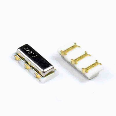
EDIT: Decided to give the resonator for the M66242 a poke also and it's cap basically fell off! I wondered if it was me being a bit rough so I grabbed one of my projects which uses these same resonators (pic below) and I put more effort into it than I did with the ones on this board, but it held firm. I obviously didn't go too far as I don't want to break it, but it definitely held up better than the 2 that came off!

Oh, and turns out the "white residue" on the ceramic is normal, this other one has it too, but looks like its a lot cleaner. The other one may have had some liquid get in as it looked a little "washed out" for lack a a better term in comparison.

« Last Edit: April 07, 2020, 09:12:20 pm by Mario87 »
 

Online Ian.M

  • Super Contributor
  • ***
  • Posts: 12860
Re: Ultrasonic cleaner broke working PCB??
« Reply #21 on: April 07, 2020, 09:26:38 pm »
Ouch!!!  It seems your ultrasonic cleaner's operating frequency must have hit a critical frequency for the lids of those resonators.  I certainly wouldn't risk it again on any electronics with delicate parts with cavities.  i.e. no resonators, crystals, metal can transistors, CERDIP ICs, MEMS sensors, multiturn trimmers etc.

Its likely that first time around the M66242 was trying to drive a resonator partially filled with conductive cleaning solution.  Hopefully it hasn't been damaged, but you wont know for sure till you get the new resonators.  Worst case, you'll have to source a NOS genuine M66242, which may be PITA, involving building a test jig controlled by something like an Arduino so you can quickly reject non-functional fakes.

Why did the 32768Hz crystal survive?  Well its internals are a very high Q tuning fork crystal, and even 0.1% off frequency wouldn't significantly excite its resonance.  Also, I'm assuming its either different construction or has a different size lid to the resonators.

Why do I recommend an IPA rinse *AFTER* distilled water?  Well if you live anywhere with significant air pollution, you can experience rapid flash rusting of any damp iron or steel surfaces that were previously protected by trace oils, greases, waxes etc. that have just been stripped off by the cleaning process.  High concentration IPA 'mops up' traces of water in crevices etc. effectively, vastly reducing the risk.     

Edit: In this current crisis, you may well want to conserve your IPA stocks for other uses.  Rapidly and thoroughly drying the board with an adjustable hot air gun set to about 100 deg C (or lower if you have highly heat sensitive components) continuing for a significant time after all visible traces of water have evaporated should be nearly as effective as it wont have time to rust, but you'll need to give it at least 24H in a warm place to be certain its dry under ICs etc. and safe to reapply power.
« Last Edit: April 08, 2020, 01:35:15 am by Ian.M »
 

Offline Mario87Topic starter

  • Regular Contributor
  • *
  • Posts: 247
  • Country: gb
Re: Ultrasonic cleaner broke working PCB??
« Reply #22 on: April 08, 2020, 07:05:02 am »
1. Ouch!!!  It seems your ultrasonic cleaner's operating frequency must have hit a critical frequency for the lids of those resonators.  I certainly wouldn't risk it again on any electronics with delicate parts with cavities.  i.e. no resonators, crystals, metal can transistors, CERDIP ICs, MEMS sensors, multiturn trimmers etc.

2. Its likely that first time around the M66242 was trying to drive a resonator partially filled with conductive cleaning solution.  Hopefully it hasn't been damaged, but you wont know for sure till you get the new resonators.  Worst case, you'll have to source a NOS genuine M66242, which may be PITA, involving building a test jig controlled by something like an Arduino so you can quickly reject non-functional fakes.

3. Why did the 32768Hz crystal survive?  Well its internals are a very high Q tuning fork crystal, and even 0.1% off frequency wouldn't significantly excite its resonance.  Also, I'm assuming its either different construction or has a different size lid to the resonators.

4. Why do I recommend an IPA rinse *AFTER* distilled water?  Well if you live anywhere with significant air pollution, you can experience rapid flash rusting of any damp iron or steel surfaces that were previously protected by trace oils, greases, waxes etc. that have just been stripped off by the cleaning process.  High concentration IPA 'mops up' traces of water in crevices etc. effectively, vastly reducing the risk.     

Edit: In this current crisis, you may well want to conserve your IPA stocks for other uses.  Rapidly and thoroughly drying the board with an adjustable hot air gun set to about 100 deg C (or lower if you have highly heat sensitive components) continuing for a significant time after all visible traces of water have evaporated should be nearly as effective as it wont have time to rust, but you'll need to give it at least 24H in a warm place to be certain its dry under ICs etc. and safe to reapply power.

Hi, just a bit more info....

1. Yes, I will not be using this cleaner again unless the board is in horrendous shape and even in that scenario, all resonators, crystals, etc will be removed!

2. I don't believe that to be the case. My reason being that when the cap came off the 5MHz resonator for the main MCU there was a black mark on the inside of the cap in the middle and the white "paint" they apply onto the ceramic itself was a bit washed out, so cleaning solution probably did get into that one. With the resonator for the M66242 the inside of the cap was spotless and the white paint stuff looked absolutely perfectly applied. If water or some other liquid had gotten inside then I'm sure it would have also looked washed out like the one for the main MCU.

3. The 32768Hz crystal is one of these...


4. Yes, I am running low on IPA now so will be more frugal with it going forward. I have ordered 3x 1L bottles from Farnell who seem to be the ones that will get some in before most others, but even that is not until 15th May!!

The company I purchased from last time has put their prices up 4-fold from £5 a litre to £20!! They do have it in stock but I refuse to be blatantly ripped off by profiteering companies in these times.

Also, I have only purchased the 5MHz resonator for the main MCU and was too late to order the 4.19MHz ones for delivery today for the M66242 by the time I found the issue with the resonator caps. My original hope was that fitting a good working 5MHz resonator would possibly kick the whole board into life as the fact it only worked when probed just wasn't right.

Now it's working even when not probed, I don't think that will now work (just replacing 1 resonator). Looking at the datasheet for the M66242 however I think it will work just fine with a 5MHz resonator. Even as an initial test I might fit one and take it from there, ordering the 4.19MHz ones after I confirm the 5MHz one actually begins to resonate at the correct frequency.

Also, one thing I could try would be to remove the resonator and the 1Meg resistor across it's pins, that way I can check and see if the IC is trying to start the resonator and being pulled low or if the IC isn't doing anything.

Reading the docs last night for muRata who make these resonators it seems the startup voltage is circa 1.5-2.0V, so if I am probing only 600-ish mA then something isn't right and the resonator will never startup with that low a voltage. Hence I am wondering if the IC's pin to being pulled low due to a bad resonator??
« Last Edit: April 08, 2020, 07:07:44 am by Mario87 »
 

Online Ian.M

  • Super Contributor
  • ***
  • Posts: 12860
Re: Ultrasonic cleaner broke working PCB??
« Reply #23 on: April 08, 2020, 08:47:50 am »
The DC bias point when not oscillating isn't a good indication of Pierce oscillator health, unless you know what its actually meant to be, or have another IC of the same type for comparison.   As long as the net loop gain is greater than unity at the initial bias point, the oscillator will start.  Is it possible you are confusing the Murata docs for plain resonators with ones for their oscillator modules that contain an internal amplifier in addition to the resonator or crystal so they implement a complete Pierce oscillator in a single package?

Anyway, another option short of IC replacement if you can't get it to oscillate with a new resonator, would be to feed an external clock to the M66242 Xin pin.  Glue a small oscillator module, preferably SMD for compactness, 'Dead Bug' style, on top of or next to the IC and use fine magnet wire to hook it up to Vcc, Gnd and Xin.

You should probably try to figure out what those M66242 PWM outputs are driving, and if its frequency sensitive, as one would expect there to be to be *some* reason* the OEM didn't reduce their BOM by speccing the same resonator for the MCU and PWM chip.

* The reason may not be good, e.g. design team inertia in a large corporation when faced by a late demand from the software team for more MIPS, or copy-pasta of a complete and fully tested PWM 'block' from a previous design.
 

Offline Mario87Topic starter

  • Regular Contributor
  • *
  • Posts: 247
  • Country: gb
Re: Ultrasonic cleaner broke working PCB??
« Reply #24 on: April 08, 2020, 09:47:45 am »
Ok, so I decided to have a poke around the resonator for the M66242 and this is what I found...

Resonator has 3 pins, lets call them XT1, GND & XT2. XT1 & XT2 have a 1 Meg resistor across them which is in good shape and reading 1 meg. I measured the resistance from XT1 to GND and it was in the megaohms, my meter goes up to 20 meg and it was reading O.L. so I measured from XT2 to GND and it was reading 142 Ohms!!

I did the same on the 5MHz resonator and both sides to GND were reading O.L. As a sanity check I took out a project I made that is connected in the same fashion with the same type of resonator, again reading O.L. between XT1 / XT2 and GND.

So I removed the resonator and just powered it up, now the output of the M66242 on the XT1 & XT2 pins are both showing 2.14V!! So the resonator was (is) bad and pulling the pins of the IC down to just 600-ish mV (sometimes when I measured it was at 850mV or there abouts).

Lucky for me I DO have another good working set of these clocks, but they are not here, I will need to go and get them. Once I have them I can measure the resonator and be 100% sure on it's operating frequency then go and buy some.

You are right, I am sure there is some reason the OEM has used a different resonator for this IC, but my plan to use the 5MHz one on it was purely just to test if it worked. After doing the above, however, I am more confident that the problem is the resonator itself opposed to the IC. So once I measure the good board I have to confirm frequency I'll just order the correct one from RS or similar.

Lesson learnt here....don't use random ultrasonic cleaners, and if you do, REMOVE resonators, crystals, etc. Just not worth it! Even if the board does come out nice and clean.

Oh, and here is the doc from muRata about the starting voltages, this is for their Ceralock Ceramic Resonators such as the one I am having difficulties with, details on page 23 (page 25 of the PDF) and it's just under 2V.... https://www.murata.com/~/media/webrenewal/support/library/catalog/products/timingdevice/ceralock/p17e.ashx

EDIT: How about this, just looking at the ceramic resonator under the microscope and as I touched it gently the ceramic fell apart into 3 pieces!! She had most certainly died a good death in the cleaner!! :--
« Last Edit: April 08, 2020, 10:06:40 am by Mario87 »


Share me

Digg  Facebook  SlashDot  Delicious  Technorati  Twitter  Google  Yahoo
Smf