-
Tektronix TDS1000B and TDS2000B series hacks
Posted by
KK
on 28 Jun, 2014 19:00
-
Anyone know of a way to upgrade bandwidth on the Tek 1000B series scopes?
Assuming the hardware is identical on the 40-70-100 MHz units.
I want to upgrade a 40mhz 1001B scope I use with iview and a logic analyzer to 100mhz.
-
#1 Reply
Posted by
KK
on 06 Jul, 2014 00:03
-
Looks like I will dissemble the firmware file to see how to change the identifier.
Any tear downs yet on these scopes - TDS1001b/1002b/1012b?
Anyone know the main processor offhand?
-
#2 Reply
Posted by
KK
on 17 Jul, 2014 20:01
-
Looks like the firmware is common for the TDS1000B/TDS2000B series Oscilloscopes.
I'm disassembling it to look at some of the remote commands. I've found some interesting things to look closer at.
VXWorks is used as the RTOS, and this scope uses a Freescale 68000 compatible processor.
-
#3 Reply
Posted by
KK
on 17 Jul, 2014 20:02
-
-
#4 Reply
Posted by
KK
on 17 Jul, 2014 20:03
-
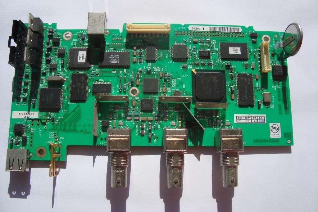
Firmware flash
Spansion
S29JL064H
64Mbit flash memory 4Mbx16
-
#5 Reply
Posted by
KK
on 17 Jul, 2014 20:04
-
DRAM. 64Mbit 512Kx32 in 4 banks.
-
#6 Reply
Posted by
KK
on 17 Jul, 2014 20:05
-
NS
ADG522
Can't find info. Must be the A/D.
-
#7 Reply
Posted by
KK
on 17 Jul, 2014 20:06
-
Unknown NS chip
EE69RD
9858-00
Another similar chip not pictured is
NS
EE63RA
9857-00
-
#8 Reply
Posted by
KK
on 17 Jul, 2014 20:07
-
-
#9 Reply
Posted by
KK
on 17 Jul, 2014 20:08
-
Main ram
SRAM 1 Mbit 64K x 16
-
#10 Reply
Posted by
KK
on 17 Jul, 2014 20:09
-
Altera Max II
EPM240
8K flash
-
#11 Reply
Posted by
KK
on 17 Jul, 2014 20:10
-
USB Driver
Cypress Semi CY7C67300-100AXI
-
#12 Reply
Posted by
nctnico
on 17 Jul, 2014 20:15
-
Highspeed SRAM 128K x 8
Must be sample memory
Probably not. The sampling memory (1k points?) is inside the sampling ASIC.
-
#13 Reply
Posted by
tautech
on 17 Jul, 2014 20:19
-
Looks like the firmware is common for the TDS1000B/TDS2000B series Oscilloscopes.
Now I'm interested.
I have TDS2102B in bits with a corroded pin on the USB chip.
I could possibly help if needed.
-
#14 Reply
Posted by
KK
on 17 Jul, 2014 23:14
-
Highspeed SRAM 128K x 8
Must be sample memory
Probably not. The sampling memory (1k points?) is inside the sampling ASIC.
Yeah, it's only 2.5K points
-
#15 Reply
Posted by
KK
on 17 Jul, 2014 23:22
-
Looks like the firmware is common for the TDS1000B/TDS2000B series Oscilloscopes.
Now I'm interested.
I have TDS2102B in bits with a corroded pin on the USB chip.
I could possibly help if needed.
Here is the latest firmware V22.16 for TDS1000B and TDS2000B series models.
The file isn't encrypted or compressed.
(too big to attach- download here)
http://www.tek.com/oscilloscope/tds1001b-software/firmware-update-tds1000b-and-tds2000b-v2216binwalk hasn't been helpful, but I have it in Ida Pro right now and I can see some interesting routines.
There are a bunch of 488.2 commands you can send it over USB using the Tektronix open choice talker/listener app.
Some of the undocumented commands from the firmware might allow for a model identifier change (bandwidth) and/or direct bandwidth change.
There are some interesting error messages in the firmware like-
Number of channels is 2 and you have selected a 4-channel Model
Display is MONO and you have selected a COLOR Model
Number of channels is 4 and you have selected a 2 channel model
Display is COLOR and you have selected a MONO model
success!; saving constants ...
-
#16 Reply
Posted by
tinhead
on 17 Jul, 2014 23:55
-
what you doing is the wrong way, the firmware is for all models, so it does not matter what inside (unless you wish to search the whole firmware for model checks and patch it then). The best way is to patch the model itself, and this has been saved somewhere. The RTC clocke does have some user bytes, but htey can't be used (without special tricks) to store model. Are there any eeproms on the board? i bet the altera cpld is readback protected, but well, just try to dump it. If the model check is really in that cpld (and not eeprom) then it is still possible to change it, e.g. by watching the bus for call just before model check in fw, and then sending the crafted info back. When eepom used, then it will be much easier. Or even simple tricks like some "not populated" parts, TEK did that on other models and one can hack them very easy (which still did't change anything, without calibration mainly useless - and to run cal one need anyway some gears, so ppl who can calobrate have enought money anyways to buy higher TEK models).
-
#17 Reply
Posted by
KK
on 18 Jul, 2014 00:17
-
Interesting ideas.
Is it possible Tektronix made one motherboard for both the model series and then configures them with commands after final assembly to what kind of model it should be. I am pursuing the theory that I can issue a command to change the max bandwidth and/or model.
I have other oscilloscopes, this is just used with my tla714 logic analyzer for iview. The type of screen it uses and feature set are mostly irrelevant as I'm looking at the waveform on Windows 7 anyway.
Bandwidth matters. I decided to buy the lowest bandwidth model because I figured hacking it up to the max would be possible.
-
#18 Reply
Posted by
KK
on 18 Jul, 2014 05:59
-
The 'B' series of these scopes introduced a USB port. Amongst the many advantages is that it works with the TLA Logic Analyzer software to overlay the scope signal with the logic analyzer signals and sync the signals.
They all have (only

) 2.5K points memory. Although that doesn't matter in my application.
TDS1000B is a 2-channel monochrome LCD Series-
1001B - 40 Mhz / 500 MS/s
1002B - 60 Mhz / 1.0 GS/s
1012B - 100 Mhz / 1.0 GS/s
TDS2000B series is a 2 or 4 channel color LCD series-
2 channels-
2002B - 60 Mhz / 1.0 GS/s
2012B - 100 Mhz / 1.0 GS/s
2022B - 200 Mhz / 2.0 GS/s
4 channels-
2004B - 60 Mhz / 1.0 GS/s
2014B - 100 Mhz / 1.0 GS/s
2024B - 200 Mhz / 2.0 GS/s
-
#19 Reply
Posted by
KK
on 18 Jul, 2014 17:18
-
Looks like the firmware is common for the TDS1000B/TDS2000B series Oscilloscopes.
Now I'm interested.
I have TDS2102B in bits with a corroded pin on the USB chip.
I could possibly help if needed.
Do you mean TDS2012B ?
Is your chipset identical to mine?
-
#20 Reply
Posted by
tautech
on 18 Jul, 2014 19:47
-
Looks like the firmware is common for the TDS1000B/TDS2000B series Oscilloscopes.
Now I'm interested.
I have TDS2102B in bits with a corroded pin on the USB chip.
I could possibly help if needed.
Do you mean TDS2012B ?
Is your chipset identical to mine?
Yes, yes.
-
#21 Reply
Posted by
KK
on 18 Jul, 2014 19:49
-
Looks like the firmware is common for the TDS1000B/TDS2000B series Oscilloscopes.
Now I'm interested.
I have TDS2102B in bits with a corroded pin on the USB chip.
I could possibly help if needed.
Do you mean TDS2012B ?
Is your chipset identical to mine?
Yes, yes.
Do the two white labeled chips flash & cpld have the same codes printed on them?
-
#22 Reply
Posted by
tautech
on 18 Jul, 2014 20:09
-
U800, F163. 166600
U801, F163. 166100. V21.20
In bits ATM.
Fails boot.
Pin 22 on U900 (USB chip) corroded through.
I need to be off grog for a week

to have a steady hand to attempt to solder a very fine wire to the pad.
Other option is replacement. Bit nervous about that, but I will just have to man up.
Got plenty of other gear, so it's low priority.
-
#23 Reply
Posted by
KK
on 18 Jul, 2014 20:32
-
Identical. So the only difference between the 1000B and 2000B 2 channel series is the display module.
Perhaps we can get these scopes up to 200Mhz
-
#24 Reply
Posted by
tautech
on 18 Jul, 2014 20:53
-
Identical. So the only difference between the 1000B and 2000B 2 channel series is the display module.
Perhaps we can get these scopes up to 200Mhz
That would turn heads.

I have no gear for any in depth sniffing etc, only a decoding DSO.
I will help if I can.
The only advice I could offer is to take note of
tinhead's interest.
-
#25 Reply
Posted by
KK
on 20 Jul, 2014 04:06
-
what you doing is the wrong way, the firmware is for all models, so it does not matter what inside (unless you wish to search the whole firmware for model checks and patch it then). The best way is to patch the model itself, and this has been saved somewhere. The RTC clocke does have some user bytes, but htey can't be used (without special tricks) to store model. Are there any eeproms on the board? i bet the altera cpld is readback protected, but well, just try to dump it. If the model check is really in that cpld (and not eeprom) then it is still possible to change it, e.g. by watching the bus for call just before model check in fw, and then sending the crafted info back. When eepom used, then it will be much easier. Or even simple tricks like some "not populated" parts, TEK did that on other models and one can hack them very easy (which still did't change anything, without calibration mainly useless - and to run cal one need anyway some gears, so ppl who can calobrate have enought money anyways to buy higher TEK models).
There is at least one flash. The main flash holds the program code, and maybe some model ID/sn. There are two other unknown chips that may have some memory.
I am more of a software guy, and have disassembled 80% of the firmware, because you know the 80/20 rule!
I found it interesting because it gives me an overview of what is going on.
My random thoughts are-
It's more complicated than I would have guessed. They are programming a USB chip, on the fly, to offload tasks.
There is a lot of printer driver code embedded. Tons of remote programming code.
What's interesting are two specialized menu's that can be enabled.
Service Mode
Engineering Mode
Service mode is documented, but doesn't do anything special.
Engineering mode, I suspect, will let you change interesting things like serial number and model type. There are error messages that prevent you from enabling 4 channels when the model hardware only has two, and color when the hardware is black & whiite.
There are no error messages for bandwidth.
Additionally, there is a lot of code for power analysis. It is enabled when a USB key is verified for TBS2PWR1
My first thoughts are that the TDS scopes can do the power analysis functions the TBS scope can. Tektronix decided to limit those functions to there TBS series.
That series also has similar bandwidth and 2.5K/points memory so I'm thinking the hardware is again identical.
The goal of this mission is to enable all bandwidth options fot the TDS1000B/2000B scopes and potentially enable the TBS2PWR1 functions since they are in the same firmware. It's not just a reference I see the entire functions and calculations in my dis assembly.
My focus now is to decode how to get into "Engineering Mode" through the front panel. Disassembly helped me find out there is such a thing.
-
#26 Reply
Posted by
tautech
on 20 Jul, 2014 04:37
-
I can read all chips #'s on my PCB.
Tell me which you need.
-
#27 Reply
Posted by
KK
on 20 Jul, 2014 21:23
-
I can read all chips #'s on my PCB.
Tell me which you need.
They match all the ones in my photos right? I think the main boards are identical.
-
#28 Reply
Posted by
KK
on 20 Jul, 2014 21:29
-
Zeroing in on it. Looking at the code that handles the front panel buttons to see the "secret" entry method.
The memory map appears to be-
0-4MB Main ram
4MB-8MB Flash program
8MB++ other hardware like usb controller etc
The model id and serial number are stored alongside the factory calibration data. These scopes let you re-calibrate through the service menu. Looking into where that data is stored.
Flash holds 4MB and the firmware file leaves about 647K free in the flash. The cal data might be at the end of the flash or it might be stored in some other chip.
-
#29 Reply
Posted by
tautech
on 20 Jul, 2014 21:41
-
I can read all chips #'s on my PCB.
Tell me which you need.
They match all the ones in my photos right? I think the main boards are identical.
Quite well.
There are minor variations with U502, 400, 301.
Looks like revisions.
-
#30 Reply
Posted by
KK
on 23 Jul, 2014 04:51
-
Whats the chip next to the USB port. I didn't pull the board all the way out of my enclosure so didn't see that one.
-
#31 Reply
Posted by
KK
on 23 Jul, 2014 05:00
-
Interesting discoveries so far...
The service mode can be entered with the following procedure-
Power on scope
Press MEASURE button
Press CH1 soft button
Press and hold SINGLE SEQ button
Press and hold AUTOSET button
Wait 5 seconds
Release SINGLE SEQ button
Release AUTOSET button
Notice lower left of screen displays "Service mode ON"
Press UTILITY button
Press SERVICE soft button
Press Service Diag. soft button
Press Peek/Poke soft button
Isn't that nice. Tektronix included a way to read or write memory, live. Any location. Right from the front panel.
I'm correlating the disassembly with some configuration memory locations in ram. I believe I can test some config changes (changing bandwidth) on the fly. It won't be permanent with this method, but it will let me confirm what part of the code is handling that process.
Engineering Mode is entered in a similar, but as of yet unknown way.
I believe I see code that lets Tektronix quickly configure models with USB keys. They insert one key to configure the model to a TDS1001B or another to configure it to a TDS1002B with higher bandwidth.
Will be looking further into both angles.
-
#32 Reply
Posted by
tautech
on 23 Jul, 2014 05:58
-
Whats the chip next to the USB port. I didn't pull the board all the way out of my enclosure so didn't see that one.
SOIC8 Atmel 24C1024W close to front panel USB
From the Tek Service manual:
Enable the Service Menu1. Power on the oscilloscope.
2. Push the front-panel MEASURE button to access the MEASURE menu.
3. Push the top option button to access the Measure 1 menu.
4. Push and hold the front-panel SINGLE SEQ button.
5. Push and hold the front-panel AUTOSET button.
6. Wait at least two seconds.
7. Release the SINGLE SEQ button.
8. Release the AUTOSET button. A message appears in the lower left corner of
the screen stating “Service mode ON.”
9. Push the front-panel UTILITY button. The last item in the Utility menu is
now “Service.”
At completion of the Adjust procedure disable the “Service” menu through the
UTILITY front panel button, the “Service” option button, and the “Service”
Mode Off” option button.
-
#33 Reply
Posted by
KK
on 23 Jul, 2014 06:52
-
24C1024W serial EEPROM 128K x 8
Aha! I wondered why I never spotted a smaller EEPROM even after suspecting there must be one.
-
#34 Reply
Posted by
KK
on 24 Jul, 2014 22:34
-
Since yours is already apart, can you read the memory and post it.
Meanwhile, I am reverse engineering the front panel code and matching it up to the key identifiers to figure out what key combo will get us into Engineering Mode.
The code is interrupt driven and creates jump tables at runtime in ram so it is a mess. The beauty of VXWORKS.
-
#35 Reply
Posted by
tautech
on 24 Jul, 2014 23:03
-
Sorry I do not have any sniffing gear.
Been wondering about getting some, what do you recommend to start with?
As far as I can tell, the 3 interconnect leads will have enough length to power up scope disassembled. Just checked, it is no problem for the 3 leads.

Then access is easy.
You may have to add a GND lead, but probably not for your needs.
There is only a few screws and all the knobs just pull off.
Service manual describes full dis-assembly. I don't remember it being difficult at all.
I can send you the manual, PM me with your email.
-
#36 Reply
Posted by
KK
on 24 Jul, 2014 23:55
-
I pulled the knobs and keys but then I noticed I would have to pull all the bnc's mounting hardware off too and just called it a night and pit it back together.
I'll work some more on the code angle.
The tll866a with an 8 pin soic clip will work without any hassle. It supports the memory and the clip means no wire mods.
-
#37 Reply
Posted by
KK
on 25 Jul, 2014 02:22
-
what you doing is the wrong way, the firmware is for all models, so it does not matter what inside (unless you wish to search the whole firmware for model checks and patch it then). The best way is to patch the model itself, and this has been saved somewhere. The RTC clocke does have some user bytes, but htey can't be used (without special tricks) to store model. Are there any eeproms on the board? i bet the altera cpld is readback protected, but well, just try to dump it. If the model check is really in that cpld (and not eeprom) then it is still possible to change it, e.g. by watching the bus for call just before model check in fw, and then sending the crafted info back. When eepom used, then it will be much easier. Or even simple tricks like some "not populated" parts, TEK did that on other models and one can hack them very easy (which still did't change anything, without calibration mainly useless - and to run cal one need anyway some gears, so ppl who can calobrate have enought money anyways to buy higher TEK models).
Hi Tinhead,
You have a great reputation here. I appreciate your interest and response.
Your thoughts are interesting, especially the parts not installed and patching the device itself.
I'm an experienced MC68000 assembly programmer, so I thought it would be fun to dive into the firmware.
Not many products use the 68000 these days. But, the fact they used VXWORKS complicates everything. The code is mostly unlabeled and jump tables are obfuscated by VXWORKS, not on purpose I think.
There is a small i2c EEPROM. That's where the interesting things are stored. I am working that angle, but enjoyed the disassembly. It brought back old memories of 68K code
-
#38 Reply
Posted by
KK
on 09 Aug, 2014 16:25
-
I disassembled the scope again and dumped the i2c eeprom. It contains the boot code for the Cypress USB controller. No config/calibration data.
The memory map so far-
000000-00FFFF RAM 64K Cypress?
010000-010FFF Memory mapped I/O?
011000-012FFF Altera Max II CPLD?
013000-0FFFFF RAM?
100000-1FFFFF Unreadable/Privilege Exception
200000-3FFFFF Ram Spansion 48lC2m3202?
400000-56BEE4 Flash memory main
56BEE5-7FFFFF Empty but is reserved for Flash memory
800000-FFFFFF Unreadable/Privilege Exception - End of addressable memory
Being a 68000, maximum address space is 16MB. But, it appears only the first 8MB has been used.
To get into Service mode requires two simultaneous key presses. Engineering mode will likely be similar, as there is code to support two simultaneous key presses, but not three. Although the hardware register shows that it can at least see up to 4 simultaneous presses.
Each key is assigned a base code, and the code is +1 if the key is held. Key codes are spaced out by 2.
Knobs are memory mapped. The memory locations for each knob (2 channel scopes have 8 knobs) store a #$FF if they are turned to the right and a #$01 if turned to the left.
The Altera CPLD has 8K of user flash. It is possible the model config, serial number, and calibration data is stored there. In fact, it is likely. There is some code to suggest the serial number is stored in the ADG522 chip which is totally undocumented. So that is one other place.
Getting in through the OS is still the ideal way if possible.
Tautech- Can you take Hires photos of your key matrix. Particularly the traces so I can see how the matrix is setup compared to a two channel scope.
-
#39 Reply
Posted by
tautech
on 10 Aug, 2014 07:36
-
KK, image sent to your email(5MB)
-
#40 Reply
Posted by
KK
on 10 Aug, 2014 20:32
-
At this point I have documented much of the boot process, and can probably just patch the firmware where it gets the model id, and force a bandwidth upgrade.
I will use that option last and would still like to figure out how to enter engineering mode.
Making a custom firmware isn't such a bad option though since it would only patch a couple of bytes and these models are long in the tooth now and Tek isn't likely to issue any future firmware updates.
-
#41 Reply
Posted by
nctnico
on 10 Aug, 2014 21:14
-
If you can force a bandwidth upgrade it would be nice to see if it has any effect. Maybe the board needs some component changes as well.
-
#42 Reply
Posted by
KK
on 10 Aug, 2014 21:20
-
If you can force a bandwidth upgrade it would be nice to see if it has any effect. Maybe the board needs some component changes as well.
It looks like the boards are identical for bandwidth options and even the 1000B and 2000B series boards appear identical.
The display module is color on the 2000B series but the Firmware is identical.
-
#43 Reply
Posted by
tautech
on 11 Aug, 2014 08:04
-
I will use that option last and would still like to figure out how to enter engineering mode.
I wonder if any ex-Tek members could contribute by way of PM?
-
#44 Reply
Posted by
KK
on 12 Aug, 2014 03:18
-
KK, image sent to your email(5MB)
Thanks for that! It helped me fill in some unknown key codes. Notice the Ref/menu button is silkscreened as Power App. On the TPS series scopes that button is labeled Application.
We should be able to activate the power application in these scopes as the code is all there. Of course, the TPS has battery operation so doing some of the measurements would require an isolation transformer on the TDS non-battery operated models.
Keycodes
Bezel 1-4
3A
3C
06
08
0A
0C Probe check
04 Print
12 Autorange
14 Ref/menu - Power App
16 Save/Recall
18 Utility
1A Measure
1C Cursor
20 Acquire
2C Display
2E Help
30 Default Setup
44 Autoset
46 Single Seq
48 Run/stop
4A Trigger Menu
58 Set to 50%
5A Force Trigger
5C Trigger View
Knobs
08 General purpose
09 Ch1 Pos
0A Ch2 Pos
0B Ch1 Volts
0C Ch2 Volts
0D Horz
0E Horz POS
0F Trigger Level
-
#45 Reply
Posted by
tautech
on 12 Aug, 2014 04:45
-
How are the key codes derived from Ch1 Volts, Ch2 Volts, and Horz ?
I realize all other buttons/knobs can be pushed, but these 3 can only be rotated L or R.
-
#46 Reply
Posted by
KK
on 12 Aug, 2014 07:59
-
The key codes come in through a memory mapped register at:
0x000A8A04
The button id is the value listed or +1 if held. That's why the button ID's are spaced by 2.
I should have been clear on the knobs, they are individually memory mapped.
The base address is:
0x000A8Axx (where xx is the code for the knob)
#$FF is stored in that location if the knob is turned to the right
#$01 if turned to the left
Might be modified by 1 if (+/-) if pushed and 2 if held. But haven't confirmed that.
I don't actually have the key codes for knob presses, but I likely don't care. What I wanted to derive is the Autoset button which your picture helped me get.
I need to look in the disassembly where the two key codes #$44 and #$46 are checked because that is how you get into service mode. I expect the code to get into Engineering to be very close to that.
The Peek/Poke utility in Service mode is crippled. Peek works, but Poke does not allow writes. Looking in the disassembly there is some way to make Poke work and it gives a warning about "Write enabled, use caution". If you try to use poke, it says "Denied".
If I can get into Poke then I could conceivable set the bandwidth flag to give 200mhz bandwidth for that powered session. Not ideal, but it would help speed along where to patch the firmware if I end up going that route.
This is one of those projects, where the target is zero'd in on slowly every day or two, with some leaps and then bingo.
-
#47 Reply
Posted by
EduardoLM
on 13 Oct, 2015 17:03
-
Sorry to revive this old thread, but I just found it, it's VERY interesting, and I would love to see this puzzle solved. Did you have any progress KK?
I own a TDS1001C-30EDU, perhaps the most crippled one on the TDS series: only 30MHz. I can open, take pictures of it and / or make tests to help you on this mission!
Hope to hear from you, thanks!
Eduardo
-
#48 Reply
Posted by
KK
on 21 Oct, 2015 23:42
-
Can't say I made any more progress as other projects caught my attention, but would like to revisit one day for fun as the 68000 CPU is one of my favorites.
-
#49 Reply
Posted by
dav
on 15 May, 2016 10:10
-
If you should find how to entering the engineering mode, please post it on the forum!

-
#50 Reply
Posted by
harm
on 28 Nov, 2016 08:40
-
Hi,
Any more news for TDS1000-2000 series hacks?
I've a TDS1002 scope with broken (monochrome) display. I want to replace/install color display. Will it work without 'hacking' the TDS1002 scope to TDS2002 and only wire the color display the right way (18pin mainboard to 15-pin display connector)?
Anyone done this before?
-
#51 Reply
Posted by
tautech
on 16 Jul, 2017 05:40
-
-
#52 Reply
Posted by
braikin
on 01 Mar, 2018 02:58
-
The process in that thread didn't work for me (TDS2004B), but I was inspired to try looking at the firmware myself. Here's some of what I found, that might help people still stumbling upon this thread.
1. The model id is stored at the end Flash ROM along side the calibration data. Here's a bit of python which would patch the ROM if you're willing to desolder and re-program it. Based on observations others have made about the hardware, and the way the code branches based on model number, this will probably work. I used a TL866 to read the rom, but haven't tried programming (see #2).
with open('ROM.BIN', 'rb+') as patchedfw:
# Model IDs
#
# 0x0B = TDS2022B
# 0x0C = TDS2024B
# 0x0D = TDS2002B
# 0x0E = TDS2012B
# 0x0F = TDS2014B
# 0x10 = TDS2022B 1GS/s
# 0x11 = TDS1002B
# 0x12 = TDS1012B
# 0x13 = TDS1001B
# 0x14 = TDS2004B
patchedfw.seek(0x7f0007)
# Update model per list above.
patchedfw.write(bytearray([0xf]))
# Update Checksum
patchedfw.seek(0x7f0004)
data = patchedfw.read(0x9f2)
bytes = [ord(b) for b in data]
csum = pack(">I", sum(bytes))
patchedfw.seek(0x7f0000)
patchedfw.write(bytearray(csum))
The address references above are the physical addresses in ROM. They're mapped differently by FPGA in firmware. If you want to peek/poke from service menu, nvram starts at 0x002f0000.
2. Looking at the code, upgrading from any sample rate to another (e.g. 1GS/s to 2GS/s) will definitely result in an uncalibrated scope. Address 0x42b340 is start method which loads cal data. The very first branch in the method matches 2GS/s models and expects the cal data to be a few bytes longer.
I don't have the capability to fix cal, so I'll probably abandon further research like finding a way to do this which doesn't require ROM removed.
-
#53 Reply
Posted by
braikin
on 03 Mar, 2018 00:11
-
Cal issue is resolved, I'll patch my ROM. If I don't break anything soldering, I'll report back what happens in a couple days.
Cal data was organized into blocks. I had a thought autocal probably manages some of these blocks too:
[factory addr=0x7f0000 sz=2546 csum=0x48242,
spc addr=0x7d652c sz=1564 csum=0x1bc53,
trig_fpc addr=0x7d0000 sz=396 csum=0x11750,
fiso_fpc addr=0x7d01c2 sz=11088 csum=0x15232b,
fiso_fpc_peak_detect_5US addr=0x7c0000 sz=11088 csum=0x14bae7,
fiso_fpc_peak_detect_10US addr=0x7c2b8e sz=11088 csum=0x16344a,
fiso_fpc_peak_detect_25US addr=0x7c571c sz=11088 csum=0x158a91,
fiso_fpc_peak_detect_50US addr=0x7c82aa sz=11088 csum=0x160cb1,
fiso_fpc_peak_detect_100US addr=0x7cae38 sz=11088 csum=0x15a601,
fiso_ch1_sample_offset addr=0x7d3d54 sz=2673 csum=0x1e307,
fiso_ch2_sample_offset addr=0x7d493e sz=2673 csum=0x105c,
fiso_ch1_pkdet_offset addr=0x7d2d50 sz=1980 csum=0x3d7d1,
fiso_ch2_pkdet_offset addr=0x7d3552 sz=1980 csum=0x325,
fiso_ch1_pkdet_lkup_corr addr=0x7d5528 sz=1980 csum=0x3dc38,
fiso_ch2_pkdet_lkup_corr addr=0x7d5d2a sz=1980 csum=0x3d71a,
trig_fpc_2 addr=0x7e0000 sz=396 csum=0x12bd9,
fiso_fpc_2 addr=0x7e01c2 sz=11088 csum=0x129b8a,
fiso_fpc_2_peak_detect_5US addr=0x7d6d60 sz=11088 csum=0x132c93,
fiso_fpc_2_peak_detect_10US addr=0x7d98ee sz=11088 csum=0x13408d,
fiso_fpc_2_peak_detect_25US addr=0x7dc47c sz=11088 csum=0x132590,
fiso_fpc_2_peak_detect_50US addr=0x7e6590 sz=11088 csum=0x1307bf,
fiso_fpc_2_peak_detect_100US addr=0x7e911e sz=11088 csum=0x12e5b2,
fiso_ch3_sample_offset addr=0x7e3d54 sz=2673 csum=0x47bef,
fiso_ch4_sample_offset addr=0x7e493e sz=2673 csum=0xf97,
fiso_ch3_pkdet_offset addr=0x7e2d50 sz=1980 csum=0x9e6d,
fiso_ch4_pkdet_offset addr=0x7e3552 sz=1980 csum=0x184af,
fiso_ch3_pkdet_lkup_corr addr=0x7e5528 sz=1980 csum=0x3d78f,
fiso_ch4_pkdet_lkup_corr addr=0x7e5d2a sz=1980 csum=0x3f20e]
The 4 sections who's size change when upgrading to 2GS/s are `fiso_ch?_sample_offset`. I did an auto cal, and observed checksum changed for those.
-
#54 Reply
Posted by
braikin
on 03 Mar, 2018 22:33
-
Success!?

Software identifies as a TDS2024B everywhere I could think to check. I
think I see more HF noise. FFT modes at 2GS/s work. 2.5ns/div works. If there's a test you'd like me to try, and I have the equipment, I don't mind giving it a try.
Obviously desoldering the the ROM isn't the easiest solution, but if you'd like to try it:
- Update to the latest firmware. V22.16. This may not be required, but this is the version I reverse engineered. Earlier firmware may or may not work.
- Desolder the ROM, dump its contents to a binary file.
- Keep a backup of the ROM file. If something goes wrong, you can only restore your unit to old firmware if you have a copy.
- Download the attached patch.py.
- If you're patching a 2ch model, change rom.write(bytearray([0x0c])) to rom.write(bytearray([0x0b])).
- Don't try to patch to an impossible configuration. You'll be left with a brick and required remove ROM and retry. Don't use a model with a different number of channels, don't user a model with a color display if you have black-white. If you make a mistake, the scope won't boot.
- Use patch.py to update your firmware, then reprogram.
- When you boot up the first time, Auto Calibration self test will fail. This isn't a problem. Just Auto Cal the scope, then cycle power.
- You're done.
Tips:
- Save a backup of old ROM, so you can rollback if needed.
- Three LEDs in upper left should light up as soon as you power on scope. If they don't maybe ROM isn't soldered well.
- If you've flashed an incompatible model number, you'll get stuck at the 3 LEDs.
-
#55 Reply
Posted by
braikin
on 04 Mar, 2018 00:51
-
Last update... unless I find out more. I'm trying to measure rise times to confirm 200mhz. Generously, the best rise times i'm seeing are > 3ns implying < 100mhz.
Changing the Product ID doesn't seem to have increased bandwidth but did seem to enable 2GS/s. Maybe there's a small hardware difference in frontend, but that's beyond my skill to figure out. Also, the `factory` section of cal which contains stuff like: model id, serial number, etc, is about 2.5 kbytes. There may be other values that need manipulation. I'll poke around firmware a little more.
-
#56 Reply
Posted by
braikin
on 05 Mar, 2018 02:51
-
According to the service manual models are required to be calibrated with a sine wave matching their respective bandwidth. Upgrading software doesn't change the fact the hardware is still calibrated to -3db @ 60mhz? Effectively cal data is limiting bandwidth? Seems like tinhead implied this early in the thread?
What the software change did do: my scope now expects a 200mhz signal during cal. So, I guess the next step is to recalibrate (if that were possible).
If I can get a crude signal source I may try out of curiosity. Calibration is reversible as long as my NVRAM survives another desoldering.
-
#57 Reply
Posted by
texaspyro
on 05 Mar, 2018 03:17
-
If I can get a crude signal source I may try out of curiosity. Calibration is reversible as long as my NVRAM survives another desoldering.
Geeeeeez, put it in a socket!
-
#58 Reply
Posted by
braikin
on 14 Mar, 2018 02:08
-
Success!
I'm now seeing rise times ~2ns which is consistent with 200mhz.
Attached is an updated python script to patch more data in NVRAM cal section. This script should work correctly with 2 and 4 channel color models upgrading them to 200mhz 2GS/s. Upgrading non-color models is possible, but not all the way to 200mhz. See my previous post for instructions just use this script instead (and there's no need to edit it).
Basically some of the bytes in factory cal section are used to program a low pass filter of some sort. It looks like They're calibrated to get a consistent attenuation across all channels and vertical scales. Instead I just set the filter to max. So... I may get more inconsistency between channels and vert scales, but it works. I think a full cal would be better but after a couple days on ebay I can't find an affordable way to do that.
If you're interested; the function `cal_bwl_setup` is defined in FW at addr 0x437230. This function programs the LPF between 20mhz and full bandwidth. The values it writes to the LPF are stored in the factory cal section. Bigger values = more bandwidth. My patch sets them to 0x0f which is the largest allowed value for 200mhz. There's on value per channel and vert scale; and like a say above they vary slightly. My scope probably performs a little less consistent.
Good to bring some life back to my old scope! I hope I don't find anymore issues. Digging any further into what the calibration bytes to would be tough.
I feel like I'm talking to myself in an 5 year old thread. If you're interested in how this applies to non-color models, or you have some tests I should try... feel free to let me know.
-
#59 Reply
Posted by
Argiros
on 29 Apr, 2018 21:42
-
I am glad that you made it! Maybe I give it a try later.
I want to say that I make a BW model to a color. I figure out the pinouts and after many search I finaly did it. I saw the red the cyan all the colors.
Unfortunately my color lcd had two spots it came with that and I put again my b/w lcd. But I finaly did it. I ordered a new color lcd and finaly i will have a color model!
-
#60 Reply
Posted by
braiden
on 01 May, 2018 13:36
-
Wow, nice work making the color display work!
Its good to know your scope works after the upgrade. It means what I've done here should work for b/w models too. I wasn't sure it would, when I accidentally programmed a model id with a channel count mismatch i got a brick. Sounds like display mismatch is more forgiving.
I still haven't been able to find affordable hardware to do a cal, but I did pick up a 500mhz freq synthesizer. Results are: frequency response is not as flat as i'd like. Everything's good through the original 60mhz. After that the sin wave amplitude creeps up (as high as 125%) before coming back to 100% at 350mhz and dropping off pretty sharply after that.
If there's interest in what you'll get with the hack I can draw a bode plot. With caveats: I assume my signal source is level (spec is +/- 0.5db). I'm using cheap cabling and termination, maybe that's adding some induction(?).
I'd like to play with the attenuation setting in cal more, but the socket i got for rom doesn't fit.
-
#61 Reply
Posted by
braikin
on 15 May, 2018 01:07
-
For what its worth, here's a plot of a nominally 3 VPP sin wave from 1-499mhz. Different test setups result in very different results. I'm using the stock P2220 probe with a BNC tip adapter plugged into a 50

passthru terminator connected directly to signal source output.
-
#62 Reply
Posted by
oaba
on 19 Jul, 2018 14:42
-
I have an TDS2002. I got the firmware out of flash Am19DL162 . How can I find the model numbers?
Hence the different firmware and flash size. Or dou you have firmwares to compare?
Thanks in advance.
-
#63 Reply
Posted by
braiden
on 19 Jul, 2018 14:56
-
I've only looked at TDS2002B, not the TDS2002 which may be totally different? If you're looking at a non-B model, there is this thread:
https://www.eevblog.com/forum/testgear/tds-1000-2000-3000-bw-hack/If its a "B" model, the model id is at 0x7f0007 in the physical ROM dump, and you should expect to find 0x0D corresponding to TDS2002B. Other model numbers are documented in patch_tds1k2kb_rom.py.txt linked above.
Within the "B" series there are no firmware differences between modules, they all run the same binary, the only relevant difference is the model and calibration data stored at the end of ROM, 0x7f0000 and 2546 bytes long.
-
#64 Reply
Posted by
vanbac
on 20 Aug, 2018 07:48
-
I am glad that you made it! Maybe I give it a try later.
I want to say that I make a BW model to a color. I figure out the pinouts and after many search I finaly did it. I saw the red the cyan all the colors.
Unfortunately my color lcd had two spots it came with that and I put again my b/w lcd. But I finaly did it. I ordered a new color lcd and finaly i will have a color model!
hello you.
modele: Tds1012b mono.
I see you've made a successful switch form screen color can you give me detailed instructions how to do thank you
-
#65 Reply
Posted by
clodnut
on 05 Sep, 2018 18:36
-
Thanks for your work on this, braikin.
Your efforts have given my aged TDS1001B (Mono, 2 Ch, 40 MHz, 500 MS/s) a new lease of life as a 100 MHz TDS1012B.
5 ns/division scaling has become available and FFT mode confirms 1 GS/s acquisition.
I tweaked your Python code to handle model ID 0x13 -> 0x12 for the TDS1000B series. Your approach of clearing the LPF settings seems to work for the TDS1000B-series, whose max. bandwith is 100 MHz rather than 200 MHz like the TDS20xxBs.
I don't have the kit to measure the new bandwidth properly but the stock probe and a Rasberry Pi outputting a square(ish) wave gives a 2.12 ns rise time, suggesting comfortably over 100 MHz bandwidth.
The calibration seems fine by eye (no weird offsets or dodgy scaling cycling through various ranges) but, again, I'm not set up to do a full cal.
Thanks again!
-
#66 Reply
Posted by
vanbac
on 09 Sep, 2018 01:56
-
hello clodnut.
Congratulations you've successfully upgraded can you guide me the steps to upgrade on YouTube thank you very much.
-
#67 Reply
Posted by
DogP
on 25 Oct, 2018 09:30
-
If you should find how to entering the engineering mode, please post it on the forum!
In this new thread:
https://www.eevblog.com/forum/testgear/tds-1000-2000-3000-bw-hack/
I didn't see engineering mode in that thread... did I miss it? In the case of the TDS 3000, the TDS3ENG hack is totally different, as it unlocks the available modules. The TDS 1000s and 2000s didn't have those modules, and instead "Engineering Mode" looks to be an option in the menu (similar to Service Mode).
Any further progress on any TDS 1K/2K stuff? I used to have one of these on my desk at work, and I just bought a 2024B for home. Not the best scope I've ever used, but nice and doesn't take up a lot of bench space... and the deal was too good to pass up. Since it's already the highest freq/sample rate 2024B, I guess there's no possible "upgrade".
I sifted through the firmware binary, and it looks like there are still some interesting mysteries to unlock. Maybe not all of them are important - engineering mode (doesn't look that interesting), the code to enable memory pokes from service mode (again, probably not very useful)... but how about the section with "A:\PAUL", "\GEORGE", "\RINGO", "\JOHN", and "A:\POLLY\LITHIUM". If I create one of those directories does it load up an XY plot of a Beatles or Nirvana album?

DogP
-
#68 Reply
Posted by
bootboot
on 06 Nov, 2018 09:45
-
Hi! Can you share me the backup ROM file?
My TDS2022B Can not bootup, it dead at 3 LEDs light.

-
#69 Reply
Posted by
vanbac
on 07 Dec, 2018 14:43
-
Hello please help me I want to upgrade the bandwidth but I read data of ROM thank you.
-
#70 Reply
Posted by
clodnut
on 08 Dec, 2018 20:23
-
U902 is not the firmware flash -- it's just an I
2C EEPROM, apparently containing the boot code for the USB controller (according to this
earlier post).
You will need to remove the S29JL064H flash memory chip, typically designated U801.
It's the one pictured in
this post earlier in this thread. It's the chip with the label in the top left of the board shown in
this post.
Then you need to read the chip, patch it using braikin's Python script and re-solder it into the scope.
Good luck!
-
#71 Reply
Posted by
vanbac
on 10 Dec, 2018 16:24
-
Thank you for the tutorial, please wait my results.
-
#72 Reply
Posted by
vanbac
on 04 Jan, 2019 06:58
-
thanks "clodnut" very much, i have upgraded the bandwidth, this is my model.
-
#73 Reply
Posted by
CaptDon
on 10 May, 2020 18:49
-
How would I run the .py script to program the flash device. I have an assortment
of programmers, but none would understand a .py script. It seems I need to unsolder
the flash rom device and insert into a programmer, I am o.k. that far, then what??
-
#74 Reply
Posted by
clodnut
on 23 May, 2020 19:41
-
Hi CaptDon,
Per my earlier message in this thread - you:
- Remove the chip
- Read it in a programmer (using whatever software is appropriate for your programmer) and save the firmware image somewhere
- Use the Python script to patch the image
- Write the altered image back to the chip
- Reinstall the chip.
Good luck!
-
-
Can any one help me to solve this issue?
I have Tektronix TDS2014B
Its shows " USB Controller Failed" ( ID NUM 17 USB Diagnostic Failed) when power up Self test.
Some time boot normally ,& some time not booting just black screen appear.
-
#76 Reply
Posted by
tautech
on 11 Jul, 2020 21:13
-
Can any one help me to solve this issue?
I have Tektronix TDS2014B
Its shows " USB Controller Failed" ( ID NUM 17 USB Diagnostic Failed) when power up Self test.
Some time boot normally ,& some time not booting just black screen appear.
Welcome to the forum.
IIRC this is what happened to my TDS2012B.

Investigation found corrosion on 1 pin of a 100 pin IC which I determined originated from a spec of debris landing on the edge of the IC as a result of the top case venting of these models that allows debris to fall into the workings of the scope.

In this case the pin looked OK but when carefully scratching the black spot away with a fine scalpel found the pin was corroded through. A very difficult repair that I have attempted a few time without success.

Yours might be easier to fix IDK.
-
#77 Reply
Posted by
bootboot
on 06 Sep, 2020 03:26
-
Hi,prafullshah61
What's the state of the LEDs on the front when your TDS2014B can not boot normally?
My TDS2022B can not bootup with black screen,3 LED light on,and the Probe's frequency is 5KHz.
I have checked the USB Controller chip(cy7c67300)'s bus and found the Add/Data works well

-
-
Which IC should I desolder for the hack on the TDS2002B, I am a complete noob on this kind of things... what is the cheapest programmer that would get the job done?
-
#79 Reply
Posted by
biju
on 16 Sep, 2020 09:42
-
some voltage level IN OK MOTHERBOARD ( Multimeter Used Fluke 179 True RMS)
-
#80 Reply
Posted by
biju
on 16 Sep, 2020 09:50
-
USB CONTROLLED FAILED show in display PLz check CY7c67300 IC VCC Voltage & FS12.00P
-
#81 Reply
Posted by
bootboot
on 19 Sep, 2020 14:21
-
My TDS2022B has different PCB.No U616 between the MC68000 and the FLASH .
-
#82 Reply
Posted by
66bono
on 14 Feb, 2021 10:29
-
Hello
I have a TDS1001B, I would like to increase its parameters, can I ask for help.
I am in satan to read flash I do not know how to use the patch. After changing the bend, could he use signal expres software.
Thank you
-
#83 Reply
Posted by
Boroda4
on 02 Jun, 2021 18:32
-
Hello
Are you read all NOR flash?
I can`t use latest version of script, and apply previos version on Win10. I edit version in script, place bin near script with ROM.BIN name and apply script. After applying i compare old and new bin in WinHex to shure of changes in shown addresses.
-
#84 Reply
Posted by
Boroda4
on 02 Jun, 2021 19:05
-
Hello to all!
Have sombody full dumps of any versions of Tek TDS1000 AND TDS2000? I need both of them.
I have both of this Tek (1001B working and 2014C not working with broken Altera) and i think so my programmer TL866 was burned NOR flash chips.
AND! I was read Altera config from 1001B via USB blaster from Ali and Quartis II! (Attached, rename type if file to .pof)
In my broken 2014C was burned Altera and USB hub. I replace both of them with new, programmed Altera with copy of one from 1001B. I don`t now what differents between Altera from 1000 and 2000, but both of them have one number on sticker. If stickers identical then config may be identical, i think

.
-
#85 Reply
Posted by
Silicium81
on 22 Mar, 2022 19:22
-
Thank's for the méthod to hack TDS2000B

I succeeded with the script to hack a TDS1001C-EDU (40MHz) to a TDS2022B (200MHz)!
I unsoldered the flash rom, read then reprogrammed with the content modified with the script. I slightly adapted it to recognize the identifier of the TDS1001C-EDU (0x28).
In pj, the modify script
-
#86 Reply
Posted by
@_Lis
on 04 Jun, 2022 05:30
-
Silicium81,
Share the firmware flash S29JL064H90TF100 from TDS1001C-EDU, please?
-
#87 Reply
Posted by
Silicium81
on 05 Jun, 2022 13:43
-
-
#88 Reply
Posted by
@_Lis
on 05 Jun, 2022 14:45
-
Silicium81,
Thank you very much!
Best regards!
-
#89 Reply
Posted by
@_Lis
on 07 Jun, 2022 04:12
-
-
#90 Reply
Posted by
@_Lis
on 08 Jun, 2022 14:55
-
Problem solved, thanks Silicium81
-
#91 Reply
Posted by
mophong
on 15 Jul, 2022 10:15
-
Hi friends,
After changing model, as I can see bandwidth was improved, how about sampling rate? Let's say we change from TDS2002B to TDS2022B, does the sampling rate really change to 2 GS/s?
Thanks.
-
-
hi
i have no easy access to doing patch using python. Instead i can do manually. i have removed flash from TDS2002B, read it on programmer. located the are in data buffer where bits needs to be modified.
i need help in locating the address where in Checksum has to be updated and Filter Confing needs be changed. how to manually calculate checksum for upgrading to TDS 2022B. screenshot of programmer data buffer attached
thanks in advance for your support
-
#93 Reply
Posted by
BG9ICN
on 07 Sep, 2022 16:03
-
I think you get some ERROES at that patch.py
When use python3, you will fail.
Try to use this patch fixed in python3 enviroment.
-
#94 Reply
Posted by
BG9ICN
on 07 Sep, 2022 16:42
-
Or you really can't use python, this is way to fix the BIN file.
Change the model at B , It should be 0B when you want tds2022b.
and change marked vaule form something to ‘0F’ in C and D.
At last, calculate how many changed you have do. For example, in B, '0E' > '0B' , that's minus 3, and there are 20 '08'>'0F' ,total add 8C, so the change is 8C-3 = 89, Then add 89 at A.
-
-
hi
myself is Novice when it come to programming. Here is what i did
i had read flash, manually changed buffer with product id from 0x0D to 0x0B at 0xf0007
and changed the checksum binary from 0x07 to 0x05 (Difference between 0x0D and 0x0B is "0x2) at 0x7f0000
didn't alter any other data relating to Filters etc. so the only data altered is the product ID
on resoldering the scope doesn't boot. green led remains lit, screen is blank. rechecked my soldering. no loose or shorts etc
can you please advise where i am going wrong. Unfortunately i am not good at programming so instead did manually what script was supposed to do.
kind regards
Vishal
-
-
hi
attached is the picture of before and after data buffer of flash ROM
-
-
thanks for the explanation with example. I think i changed checksum at wrong address.
few question
1. as per python script the checksum was supposed to be at 0x7f0000. However the "A" is at different address
2. Position "A" in your example has data 0x28AC
3. so it as per the example it will now be 0x2935
so in my case i am just changing the product id from 0x0D to 0x0B. The difference is 2. so 200A now will be 2008
is my understanding correct. I have 3 Ghz Rigol Sig Gen. Will try to do fresh cal after upgrade. that is why i am not changing the cal data
-
#98 Reply
Posted by
BG9ICN
on 08 Sep, 2022 17:31
-
7F0000H is right. The completed checksum is '00 07 28 AC' in this example. The marked zone is just data changed.
And 08>0F is for operate the LPF, it's different from cal data.
-
-
HI
Many thanks for your explanation.
I will try this out and will let you know if i succeed
-
-
unfortunately this didn't work for me. scope doesnt boot.
i had verified the data buffer twice before programming. no issues with soldering
product id programmed is 0x0B (for TDS2022B).
if for some reason the checsum isn't correct, will the scope boot?
-
-
pics of soldering Flash after re programming
-
#102 Reply
Posted by
DogP
on 11 Sep, 2022 05:25
-
I haven't personally done a firmware upgrade (mine is already a 2024B), so I don't have any personal experience... but looking at the picture, the soldering on pin 2 in particular looks suspect. The pad of pin 1 and/or pin 2 looks like it might be lifted as well (or maybe it's just the solder that makes it look crooked).
I guess you could try removing the chip again, reflashing to the stock, and making sure it still works... though of course the pins and pads are delicate, so I'd only try that if you think they're in good enough shape to hold up to the extra soldering cycles.
DogP
-
-
hi,
i did noticed that, and did some touching with no success.
i could see some waveforms on it when probed with another scope, which means some bus activity happened in the past.
neverthess will check again. the two pins are from address bus. if there is activity on these, it means they are connected
-
-
checked with DMM, these are not shorted.
just after power on, there is a bus activity on these for few seconds.
this means they are connected and main processor is accessing active.
something else is not correct.
Will give a last attempt of removing rom. Else there is a possibility of loosing some pads thus making board of no use
-
-
hi
as per python scirpt, there are two different ID for TDS 2022B
0x0D and 0x10
what is the difference between two?
-
-
i noticed Firmware version is 22.01 .
could that be the reason for the hack not working
-
#107 Reply
Posted by
BG9ICN
on 15 Sep, 2022 15:59
-
Try to flash back the read-out version.
And check what did you changed. If you change another block, system doesn't startup.
Two TDS2022, one is 1GSa/s, the other is 2GSa/s.
-
-
i flashed back the original FW and re soldered. its still not booting.
there is activity on data bus for few seconds and then it gives up. further the probe compensation signal is at 5 Khz.
it seems either the flash is faulty or it was not properly read during the first instance. Though, before saving the original ROM, i ready it for 3 to 4 times. Every time check sum was same.
Also noticed that when i remove the flash from board and try to compare it with image ( i copied into) there is a small variation in the check sum between flash contents and image file. it seems that some content changed either by scope or due to faulty flash.
had checked with another working unit. There is no signal if flash is missing. soon after power up, it is at 5Khz, then as it boots up, it changes on to finally at 1Khz. as per service manual 1 Khz means booting is okay.
now need to get a confirmed working flash from another scope to troubleshoot further.
-
#109 Reply
Posted by
Fieroluke
on 18 Sep, 2022 18:38
-
You could get the bin file from
http://www.ko4bb.com/ (search TDS1001C) and see if that works?
Sounds like your flash is damaged or the initial readout failed? Using the file from KO4BB might help…
-
-
thanks but i need file for 2 channel B model
C model file may not work
-
#111 Reply
Posted by
Fieroluke
on 28 Sep, 2022 16:24
-
I report success changing a TDS2001C (50 MHZ / 500Ms/s) to TDS2022B (200 MHz/2 Gs/s)!
The firmware installed was v24.09. The board seemed the same, Flash was also 8M Spansion S29JL064H so I bit the bullet. The model ID is 0x1D, same address 0x7F0007.
Since I’m not a Python person I patched directly in the EPROM editor. Filters also started at 0xF700B6, all 05’s in the first block, 05’s and 06’s in second block. Changed them to 0x0F.
Checksum is 0x7F0004 to 7F09F9. My programmer (Galep5) could calculate that, so I transferred the new checksum to 0x7F0000.
First boot took longer than usual and I thought I killed the board, but then the boot screen reported as 2022B with self cal failure. Self calibrated, and viola: personality change! Strangely the firmware now identifies as v24.26, even though it’s 24.09 that I changed. I don’t know how Tek calculates revision numbers.
But bandwith reports 200 MHz, timebase goes down to 2.5 ns. Don’t know where else to check, but it seems to be working!
P.S.: Maybe someone wants to update the python script…
-
#112 Reply
Posted by
Fieroluke
on 29 Sep, 2022 18:25
-
Interesting information:
Tek says the difference between the B and C series
https://www.tek.com/-/media/documents/faq6520.pdf is basically a bit more bandwidth for the low end models, a better TFT and a few more Measure and Utility entries, RMS, duty cycle and others.
After setting the model code to TDS2022B the big question is: does the scope still have the C-series firmware’s features?
The answer is YES, the measure menu now contains all the new entries! So (not owning a 2022B model) apparently v22.16 seems to be the latest firmware for the 2022B, but changing a 2001C to 2022B takes it to v24.26! So maybe Tek just blocked the firmware from loading on older hardware?! Maybe just setting the 2022B’s model code to 0x1D will let you update to v24.09, and then resetting the model code magically transforms the v24.09 to v24.26…?
And ideally if we knew the model code for the TDS2022C (probably between 0x15 and 0x27), we could change any 2000c model directly to 2022c…
-
-
hi,
this is really interesting to note.
there is a hardware difference between B and C series. B series display is CCFL type and C is of LED type. Apart from this C series has a small interface board (with FPGA and led driver) between display and connector on motherboard and actual display.
i had once tried to use connect LED display from C series (along with interface board) to B series but it doesnt work. which means the data data from motherboard is different.
so i wonder how come the updated b series is now able to drive a LED board? or this could also mean there was a revision in board for B (supporting LED display) as well and the new FW supports B series models as well
for my board i need a bin file of 2 channel B series model
-
-
just to add here.
the fw file have an extension *.tek
C series FW file should not work unless it is renamed and "C"at the end is replaced by "B"
i did an experiment today. for a C model used a FW file of B model (after replacing C with B)
at the end scope said fw update done, press ok. the screen went blank and the scope got bricked.
fortunately i have a kept a copy of original ROM to restore it back
-
#115 Reply
Posted by
Fieroluke
on 04 Oct, 2022 14:37
-
Don't use the *.TEK files, they don't work. I'm sure they have a block in there.
Unsolder your Flash, read it, and modify it by running the Python script (or manually like I did), then solder it back.
That way it's YOUR firmware, just a different model ID in the firmware.
Apparently the firmware uses the same base software, which switches features based on model ID, and maybe a driver portion, that is custom to the B and C series.
Impossible to know without comparing firmwares. Anyway, modifying this ID byte in YOUR SCOPE's firmware removes the limitations in the base firmware and also changes the model ID string associated with it, but keeps the drivers for the ModelB or C series. That would explain it.
This is a list from inside the C-Firmware that lists all supported models I guess (I don't know what the -SC models are (school = EDU?)):
TDS2002B 0x0D
TDS2012B 0x0E
TDS2022B 0x0B
TDS2004B 0x14
TDS2014B 0x0F
TDS2024B 0x0C
TDS2022B_1G 0x10
TDS1001B 0x13
TDS1002B 0x11
TDS1012B 0x12
TDS1001B-SC 0x15
TDS1002B-SC 0x16
TDS1012B-SC 0x17
TDS2002C 0x1A
TDS2012C 0x1B
TDS2022C 0x18
TDS2001C 0x1D
TDS2004C 0x1E
TDS2014C 0x1C
TDS2024C 0x19
TDS1001C-SC 0x1F
TDS1002C-SC 0x20
TDS1012C-SC 0x21
Note there’s no apparent order in this list. Ordering by known IDs it seems the “full” version 2024B starts the list, then the most limited 50 MHz 2002B, then 100MHz 2012B, 2014B, next sample limited 200MHz 2022B. Next up are the monochrome versions, but in random order. And at the end of the list come the C models.
It looks like the order was determined by chronological order and marketing department, lol.
[edited: updated model IDs according to my findings later in this thread]
-
-
sucess finally.
i used a stock fw from C series 4 channel and replaced the cal data from my original unit.
The unit now boots up with model TDS2022B, shows 16 measurements as stated in C model and now supports led type display from C model.
Thanks everyone for support
-
#117 Reply
Posted by
Fieroluke
on 12 Oct, 2022 06:33
-
Awesome news, congratulations!
-
#118 Reply
Posted by
Fieroluke
on 10 Feb, 2023 17:00
-
I dug a little deeper into my dumped ROM and I think I deciphered the model code list. The relevant code starts at ROM-Offset 0x30C9FA / address $50C9FA:
(this is disassembled by hand, but you get the idea. Use the info below at your own risk!)
			.org $50C9FA
4E56 0000		link A6,#0              ;set up stack frame
2F0A 			move.l A3,-(SP)         ;save A3
246E 0008 		move.l A4,8(A6)         ;pass parameter to get device ID
6100 02F8 		bsr 	$2F8(PC) 	;get device ID $50CCFE: CAL_get_instrument_config()
72F5			moveq.l #$F5,D1  	;-0x0B
D081			add.l D1,D0 		;subtract offset for first ID code
7216 			moveq.l #$16,D1		;index 22 is last entry in table
B280			cmp.l D1,D0 		;check overflow
6500 0100 		bcs $100(PC)		;branch on error

D080 			add.l D0,D0		;double D0 for table index, because we're addressing words
303B 0806		move.w 6(D0,PC),D0	;get jump offset word from table
4EFB 0002		jmp 2(PC,D0)		;jump to model code
So, this part gets a jump offset from the jump table immediately following the code. This jump table determines where to continue the code depending on the model ID. 0x0B is the first model ID and is the first table entry:
			.org $50CA1E
			dc.w $42 ;$50CA60 - TDS2022B $0B
			dc.w $60 ;$50CA7E - TDS2024B $0C
			dc.w $2E ;$50CA4C - TDS2002B $0D
			dc.w $38 ;$50CA56 - TDS2012B $0E
			dc.w $56 ;$50CA74 - TDS2014B $0F
			dc.w $6A ;$50CA88 - TDS2022B_1G $10
			dc.w $7C ;$50CA9A - TDS1002B $11
			dc.w $84 ;$50CAA2 - TDS1012B $12
			dc.w $74 ;$50CA92 - TDS1001B $13
			dc.w $4C ;$50CA6A - TDS2004B $14
			dc.w $8C ;$50CAAA - TDS1001B-SC $15
			dc.w $94 ;$50CAB2 - TDS1002B-SC $16
			dc.w $9C ;$50CABA - TDS1012B-SC $17
			dc.w $B4 ;$50CAD2 - TDS2022C $18
			dc.w $D4 ;$50CAF2 - TDS2024C $19
			dc.w $A4 ;$50CAC2 - TDS2002C $1A
			dc.w $AC ;$50CACA - TDS2012C $1B
			dc.w $CC ;$50CAEA - TDS2014C $1C
			dc.w $BC ;$50CADA - TDS2001C $1D
			dc.w $C4 ;$50CAE2 - TDS2004C $1E
			dc.w $DC ;$50CAFA - TDS1001C-SC $1F
			dc.w $E4 ;$50CB02 - TDS1002C-SC $20
			dc.w $EC ;$50CB0A - TDS1012C-SC $21
So, this jumptable jumps to the following code, which loads the model ID from a nearby string table:
			.org $50CA4C
24BC 0050C916		move.l #$050C916,(A2)	;TDS2002B
6000 00C4		bra.w $C4(PC)

			.org $50CA56
24BC 0050C91F		move.l #$050C91F,(A2)	;TDS2012B
6000 00BA		bra.w $BA(PC)

			.org $50CA60
24BC 0050C928		move.l #$050C928,(A2)	;TDS2022B
6000 00B0		bra.w $B0(PC)

			.org $50CA6A
24BC 0050C931		move.l #$050C931,(A2)	;TDS2004B
6000 00A6		bra.w $A6(PC)

			.org $50CA74
24BC 0050C93A		move.l #$050C93A,(A2)	;TDS2014B
6000 009C		bra.w $9C(PC)

			.org $50CA7E
24BC 0050C943		move.l #$050C943,(A2)	;TDS2024B
6000 0092		bra.w $92(PC)

			.org $50CA88
24BC 0050C94C		move.l #$050C94C,(A2)	;TDS2022B_1G
6000 0088		bra.w $88(PC)

			.org $50CA92
24BC 0050C958		move.l #$050C958,(A2)	;TDS1001B
607E 			bra.b $7E(PC)

			.org $50CA9A
24BC 0050C961		move.l #$050C961,(A2)	;TDS1002B
6076 			bra.b $76(PC)

			.org $50CAA2
24BC 0050C96A		move.l #$050C96A,(A2)	;TDS1012B
606E 			bra.b $6E(PC)

			.org $50CAAA
24BC 0050C973		move.l #$050C973,(A2)	;TDS1001B-SC
6066 			bra.b $66(PC)

			.org $50CAB2
24BC 0050C97F		move.l #$050C97F,(A2)	;TDS1002B-SC
605E 			bra.b $5E(PC)

			.org $50CABA
24BC 0050C98B		move.l #$050C98B,(A2)	;TDS1012B-SC
6056 			bra.b $56(PC)

			.org $50CAC2
24BC 0050C997		move.l #$050C997,(A2)	;TDS2002C
604E 			bra.b $4E(PC)

			.org $50CACA
24BC 0050C9A0		move.l #$050C9A0,(A2)	;TDS2012C
6046 			bra.b $46(PC)

			.org $50CAD2
24BC 0050C9A9		move.l #$050C9A9,(A2)	;TDS2022C
603E 			bra.b $3E(PC)

			.org $50CADA
24BC 0050C9B2		move.l #$050C9B2,(A2)	;TDS2001C
6036 			bra.b $36(PC)

			.org $50CAE2
24BC 0050C9BB		move.l #$050C9BB,(A2)	;TDS2004C
602E 			bra.b $2E(PC)

			.org $50CAEA
24BC 0050C9C4		move.l #$050C9C4,(A2)	;TDS2014C
6026 			bra.b $26(PC)

			.org $50CAF2
24BC 0050C9CD		move.l #$050C9CD,(A2)	;TDS2024C
601E 			bra.b $1E(PC)

			.org $50CAFA
24BC 0050C9D6		move.l #$050C9D6,(A2)	;TDS1001C-SC
6016 			bra.b $16(PC)

			.org $50CB02
24BC 0050C9E2		move.l #$050C9E2,(A2)	;TDS1002C-SC
600E 			bra.b $0E(PC)

			.org $50CB0A
24BC 0050C9EE		move.l #$050C9EE,(A2)	;TDS1012C-SC
6006 			bra.b $06(PC)

			.org $50CB12
24BC 0050C7E9		move.l #$050C7E9,(A2)	;XYZZY (Interesting!)
I have added the strings which the address points to as a comment for your convenience. So, now you can happily chance between model IDs. You're welcome!
-
#119 Reply
Posted by
Fieroluke
on 10 Feb, 2023 17:28
-
There's an error in the previous post I think.
The checksum is from 0x7F0004 to 0x7F09F5. Make sure you select the correct region and your checksum routine calculates the same value that is at 0x7F0000-0x7F0003 before changing the buffer!
-
-
Hi,
sucess finally.
i used a stock fw from C series 4 channel and replaced the cal data from my original unit.
The unit now boots up with model TDS2022B, shows 16 measurements as stated in C model and now supports led type display from C model.
Thanks everyone for support
By "stock fw" you mean a flash dump from a working unit, right? And is the "original unit" a TDS2000B series?
I got a TDS2014B with (probably) corrupted FW. At least it shows the typically symptoms, meaning the three green LEDs. I already desoldered the flash and read it out.
My expectations were to see mostly 0xFF, but there is nothing obviously wrong in there. So maybe an update was interrupted just before the finish line?
Is it possible to take the TDS1001C FW from ko4bb.com and put my cal data in there? Or does someone maybe have a readout from a 2000B series unit?
-
#121 Reply
Posted by
Fieroluke
on 24 Feb, 2023 16:02
-
Success again!
Changed my TDS2001C from TDS2022B (ID $0B) to TDS2022C (ID $18)
-
#122 Reply
Posted by
66bono
on 24 Feb, 2023 19:37
-
@Use the Python script to patch the image
How do I use the script, paste on USB and update. I have no idea, I made a copy of U 801

-
-
Install python 2.7. and run
python patch2.py rom.bin
This worked for me (I haven't tried the updated pxthon3 script). Then write the flash the same way you read it. You cant put the update on a USB stick.
Edit:
I now see you have a TDS1001B and the patch2.py does not include that in the model check. To which model you want to update your scope?
-
#124 Reply
Posted by
Fieroluke
on 25 Feb, 2023 08:36
-
If the scope is a TDS1001B it should be model ID $13 at $7F0007.
Changing it to $12 should result in a TDS1012B, which should be all that’s possible upgradewise.
-
#125 Reply
Posted by
66bono
on 25 Feb, 2023 08:40
-
TDS1001B
I read the batch and soldered the S29JL064H70TFI00 again. The oscilloscope works as before.
No idea about programming
I wanted to get the highest possible bandwidth.
I also experimented with OpenChoice Talker Listener
I established communication, failed to break the oscilloscope
-
#126 Reply
Posted by
Fieroluke
on 25 Feb, 2023 08:50
-
The pitbull hack doesn’t work with the B-series scopes.
Check location 7F0007 of the file you programmed into the firmware. Which value does it have?
If the py-script didn’t recognize your scope, the file didn’t get modified and you programmed the original file again.
Which model does the startup screen report? (The „set time and date“-screen)
-
#127 Reply
Posted by
66bono
on 25 Feb, 2023 09:05
-
I didn't change the original bin file. I just read it with the programmer and soldered the again
-
#128 Reply
Posted by
Fieroluke
on 25 Feb, 2023 11:59
-
Don’t look for content 7F0007, look at ADDRESS 7F0007! The part on the left (blue) should be 7F0007 or 7F0000.
-
#129 Reply
Posted by
66bono
on 25 Feb, 2023 12:39
-
7f0007 not found is 7f0008
-
#130 Reply
Posted by
Silicium81
on 25 Feb, 2023 14:36
-
7f0007 not found is 7f0008
the content of 7f0007 is here:
-
#131 Reply
Posted by
Fieroluke
on 25 Feb, 2023 15:43
-

Perfect. 13 (circled red) means it‘s a TDS1001B. Change it to 12 to make it a TDS1012B.
00072CC4 is the checksum. If you change 13 to 12 the checksum needs to change to 00072CC3.
But you need to change the filter banks too. It‘s described in reply #94 of this thread.
Change the 20 filter values to 0F and adjust the checksum accordingly! If you don’t, it won’t work!
-
#132 Reply
Posted by
66bono
on 26 Feb, 2023 16:27
-
Thanks for explanation.
I looked for addresses to change. The obscured area is the serial number.
13 is the model we change to 12.
Filters are 2x 10 (04) I change to 2x 10 (0F)
I can't handle the checksum either.
-
#133 Reply
Posted by
Fieroluke
on 26 Feb, 2023 17:12
-
Ok, bear with me…
You change the model ID from 13 to 12: -1
You change 04 to 0F, 20 times: 20 x $0B = $DC
Total change: $DB
So new checksum should be (try at your own risk): $00072CC4 + $DB
=> new checksum should be hex 00 07 2D 9F
-
#134 Reply
Posted by
66bono
on 26 Feb, 2023 18:37
-
I changed
I have a copy of the original, if something goes wrong, I can restore the original file.
Will there be a brick:)
-
#135 Reply
Posted by
Fieroluke
on 26 Feb, 2023 18:54
-
Biting my nails now…
Please report the outcome!
-
#136 Reply
Posted by
66bono
on 26 Feb, 2023 18:58
-
I'll try tomorrow
Thank you foryour help.
I compared 2 files and only the values marked in red are changed.
-
#137 Reply
Posted by
66bono
on 27 Feb, 2023 10:05
-
He started, thank you very much.
LVDS 74MHz
-
#138 Reply
Posted by
Fieroluke
on 27 Feb, 2023 10:51
-
Reporting success on a TDS2004C turned 2024C! Model ID changed from 1E to 19.
First I was sceptical, because the Flash was nowhere to be found, but it’s just on the solder side of the PCB and actually easier to remove.
For 4 channels there were four filter banks of 10 values each to change from 07 to 0F, other than that, straightforward. Initially reports self cal fails and clock was reset, but after self calibration and setting time and date, boots smooth as silk :-)
-
#139 Reply
Posted by
Yuriy V.
on 15 Apr, 2023 19:30
-
Very, very interesting thread!
I have Tek TDS1002B & may be I will try to level up it
-
-
After repairing and upgrading two scopes I want to point out that -SC is not the same as -EDU. The EDU firmware will only boot if the device ID is EDU (0x28 for TDS1001C-EDU or 0x2A for TDS1012C-EDU) or if the ID is a B model (probably same firmware base?). 0x28 and 0x2A are not listed in the firmware that Fieroluke disassembled, so if you update an EDU model with C Model firmware, the scope wont boot. And I assume that the EDU firmware knows only about EDU and B model IDs, not Regular C models.
However, you can put the C firmware in a EDU device, desolder the flash, change the ID to a C model and update the CRC. That way I upgraded a TDS1012C-EDU to TDS2022C.
Another way would be to keep the EDU firmware and only changing the ID to TDS2022B, but it looks like the C firmware has more features.
And to answer my own question from earlier:
https://www.eevblog.com/forum/testgear/tektronix-tds1000b-series-hacks/msg4705982/#msg4705982the EDU FW (like the one found on ko4bb.com) will not work on a B model hardware!
-
#141 Reply
Posted by
lern01
on 21 Oct, 2023 10:56
-
Hi Fieroluke, I have a tds1012c, can I upgrade to 2024c, can you help me? Thank you very much!
-
#142 Reply
Posted by
Fieroluke
on 21 Oct, 2023 11:54
-
No, you can‘t change 2 to 4 channels.
Changing from b/w to color is said to be possible, but I have no experience with that.
So, getting a screen and assorted components from a tds2000c series scope may be possible, but probably cheaper to get a working color model for cheap.
And for the monochrome TDS1000 series, your TDS1012C seems as high as it can go.
-
#143 Reply
Posted by
lern01
on 23 Oct, 2023 10:08
-
Sorry, Is it possible to upgrade to TDS2022C?
-
#144 Reply
Posted by
vdetal
on 23 Oct, 2023 21:59
-
Works with monochrome display too.
Tested on 2 pcs 1001B.
-
#145 Reply
Posted by
phecap
on 24 Oct, 2023 06:33
-
I have a Tektronix TDS2024B.
Does anyone know if it is possible to upgrade this oscilloscope to TDS2024C?
Or is this not possible due to the hardware differences?
-
#146 Reply
Posted by
Fieroluke
on 24 Oct, 2023 06:48
-
That should work. The main difference is the better LCD I think
-
#147 Reply
Posted by
vdetal
on 27 Oct, 2023 22:16
-
You can, it's very simple. Download the latest firmware for the C-series from the Tek website. (this is TDS1K2KC_V24.26_066134800.zip). Unpack. It works for me if I rename the .tek firmware file. Rename the file TDS1K2KC.TEK to file TDS1K2KВ.TEK, write to a USB flash drive (I use 2GB). Well, then insert it into your TDS and follow the instructions.... Here is the result of the update with 2 different versions and it works even on a monochrome display:
-
#148 Reply
Posted by
lern01
on 03 Dec, 2023 13:53
-
You can, it's very simple. Download the latest firmware for the C-series from the Tek website. (this is TDS1K2KC_V24.26_066134800.zip). Unpack. It works for me if I rename the .tek firmware file. Rename the file TDS1K2KC.TEK to file TDS1K2KВ.TEK, write to a USB flash drive (I use 2GB). Well, then insert it into your TDS and follow the instructions.... Here is the result of the update with 2 different versions and it works even on a monochrome display:
Has your TDS1001B been upgraded to 2022B?
-
#149 Reply
Posted by
lern01
on 03 Dec, 2023 14:08
-
Success again!
Changed my TDS2001C from TDS2022B (ID $0B) to TDS2022C (ID $18)
Hello, I have a TDS2002C, I haven't understood your operation of modifying the checksum. Can you upload the pictures you performed on the eeprom editor? Or send me your 2022C firmware to lern01@outlook.com. Thanks!
-
#150 Reply
Posted by
vdetal
on 03 Dec, 2023 15:07
-
您的TDS1001B升级到了2022B?
Yes!
-
#151 Reply
Posted by
lern01
on 24 Dec, 2023 04:01
-
Congratulations, mine was successful too. Thanks to all netizens for their help.
-
#152 Reply
Posted by
lern01
on 24 Dec, 2023 04:15
-
However, I encountered a new problem. I have a TDS2014C, which was upgraded to 2024C, but three green lights are always on when I turn it on, and the screen lights up and goes dark for a while. Programmed back to the original 2014C firmware, same fault phenomenon. The flash solder joints were checked under a microscope and everything seemed fine. Measure the square wave output. One moment it is 5KMHz, the next moment it becomes 7.597KMHz, and the cycle repeats.
-
#153 Reply
Posted by
lern01
on 24 Dec, 2023 09:13
-
This oscilloscope seems to be a new model, as shown in the picture
-
#154 Reply
Posted by
Fieroluke
on 24 Dec, 2023 10:03
-
Hi,
It sounds like the scope crashes during the boot process and is stuck in a reboot loop.
Since the problem persists even with the original firmware you have a hardware problem!
Either a bad EPROM (verify?) or PCB damage. Torn trace? Damaged via? Short?
Sometimes a PCB picks up a piece of solder or wire shorting something.
You can try inspecting the upper address lines for a short or unusual waveform, because shorts show (usually you see a third level besides high and low compared to the other address / data lines)!
I assume the data bus and lower address lines are probably ok because it seems to run the boot process for a bit before crashing.
Good luck
-
#155 Reply
Posted by
lern01
on 25 Dec, 2023 01:48
-
Hi,
It sounds like the scope crashes during the boot process and is stuck in a reboot loop.
Since the problem persists even with the original firmware you have a hardware problem!
Either a bad EPROM (verify?) or PCB damage. Torn trace? Damaged via? Short?
Sometimes a PCB picks up a piece of solder or wire shorting something.
You can try inspecting the upper address lines for a short or unusual waveform, because shorts show (usually you see a third level besides high and low compared to the other address / data lines)!
I assume the data bus and lower address lines are probably ok because it seems to run the boot process for a bit before crashing.
Good luck
Thank you very much for your reply. The EPROM is good and the PCB has been checked repeatedly. There is no solder residue or damage. Which "upper address lines" do you mean? Hope to get further guidance. Sorry, I'm a newbie.
-
#156 Reply
Posted by
lern01
on 25 Dec, 2023 04:14
-
Reporting success on a TDS2004C turned 2024C! Model ID changed from 1E to 19.
First I was sceptical, because the Flash was nowhere to be found, but it’s just on the solder side of the PCB and actually easier to remove.
For 4 channels there were four filter banks of 10 values each to change from 07 to 0F, other than that, straightforward. Initially reports self cal fails and clock was reset, but after self calibration and setting time and date, boots smooth as silk :-)
I suspect that there is something wrong with the 2014C firmware that I dumped earlier because I forgot to verify it after dumping it. Today I used TL866 to read the EPROM again. After reading and verifying, an error occurred. It was the same after repeated several times. Can you send me a copy of the 2024C firmware? grateful! Email:lern01@outlook.com
-
#157 Reply
Posted by
lern01
on 11 Jan, 2024 15:02
-
In the process of upgrading TDS2014C to TDS2024C, I have a problem. Please pay special attention to it and upgrade carefully to reprogram the original chip. After I used TL866 to dump the TDS2014C firmware (the firmware dump is absolutely fine and has been verified N times), even if it is not cracked and I use other chips to program the firmware dumped by TDS2014C, the oscilloscope's self-calibration fails, but other functions are normal. The fourth step of the V24.09 version failed, and the first step of the V24.26 version failed. Welded back the original chip (the chip has not been touched, the original firmware), and the oscilloscope passed the self-calibration. It is suspected that something is set in the EPROM chip. Does anyone know how to solve it?