Author Topic: Test Equipment Anonymous (TEA) group therapy thread  (Read 15319806 times)

duckduck and 10 Guests are viewing this topic.

Offline med6753

  • Super Contributor
  • ***
  • Posts: 11314
  • Country: us
  • Tek nut
Re: Test Equipment Anonymous (TEA) group therapy thread
« Reply #9375 on: April 16, 2018, 02:55:47 am »
bd189...this might interest you. I recall you stating your dissatisfaction with a Fluke 8000A you had in your collection due to it's power supply design. I also have an 8000A and of all the Flukes in my collection it displays the most drift as it fully warms up. I traced much of that drift to the power supply and I made some mods that seemed to help. Here's some background...

When I purchased the 8000A it seemed to work fine but as insurance I re-capped the power supply. I did notice at the time that the +/- 15V supply did read a little low I figured it was OK. The unregulated +5V supply was about 5.1 – 5.2 volts. After I work on a DMM I like to give them an extensive burn-in before a final calibration. That's when I noticed what I consider excessive drift of nearly 40mV on the 20V range from initial power on to about 1.5 – 2.0 hours later. First picture is initial power on with an 8600A connected to same source as a reference. Usually would read +9.99V but sometimes +9.98V. 2nd picture is about 1.5 hours later. 10.01V and sometimes 10.02V. Almost 40mV total. I consider that unacceptable so I decided to see if I could fix it.

Next picture is the 8000A power supply. I think it was you that mentioned Q24 and Q19 develop high leakage over time. Certainly seems to be the case. The +15V supply varied around +14.1V to +14.3V. The -15V supply -13.8V to -14.0V. Rather than replace those transistors I decided modify these circuits with modern linear regulators. I removed Q24, R7, and CR8 and installed a 7815 regulator. Removed Q19, R49, and CR9 and installed a 7915 regulator. The result? +15V now a solid +14.84V. -15V now a solid -14.87V.

How did affect overall drift? Last picture is initial power up. Solid +10.00V. As the DMM warms up it varies down sometimes to +9.99V but back up to +10.00V. And after several hours may occasionally display +10.01V. So it seems this mod cut the overall drift by about 50% or 20mv. Much improved and I don't think I'll be able to achieve much better. I've thought about installing a 7805 regulator in the +5V supply but that's going to require extensive modification and I'm not sure it will yield any results.

So there you have it. It's an easy mod that definitely gives positive results. And yea...you could say I'm a volt-nut.       
An old gray beard with an attitude.
 

Offline mnementh

  • Super Contributor
  • ***
  • Posts: 17541
  • Country: us
  • *Hiding in the Dwagon-Cave*
Re: Test Equipment Anonymous (TEA) group therapy thread
« Reply #9376 on: April 16, 2018, 04:56:41 am »
I think we have a simple misunderstanding here; that of OT vs reasonable place to ask for help. This is not an unreasonable place to ask for help; you just have to understand that it's a gamble as to whether anyone here has actually done the repair you're contemplating and can help. If not, then you'll not get anyone who can answer; it's that simple.

Other threads may be more likely to have users with the knowledge in question; that doesn't necessarily mean they have the time or inclination to help neo grok in fullness. ;)

I don't think it was unreasonable for neo to ask in here; he knows there are a lot of good-hearted folks who frequent the forum who would be INCLINED to help, and maybe even able & willing to break it down into simpler terms he can more readily digest. This is often not the case with more technically-oriented threads.

When asking for help, you need to consider both; I think he just decided to ask here where he felt like he had friends first.

neo, I don't know enough about the data structure of the NVRAM in question to help you read it with an EEPROM burner; that was why I suggested you do the "shoot video of the memory dump from withing the service menu" method mentioned in several of the threads I linked to when you first asked about this.

Right now, what I'd do is clean up the pins on the chip, install a low-profile DIP socket on the mainboard and then reinstall the DS1225 to see if the scope still appears to work properly. If so, get that video back up of the data ASAP.


Cheers,

mnem
I fought the lawn and the lawn... LOST!  ;D

Thank you, you hit the metaphorical nail right on it's head, Too late to reinstalled the original, broke a pin on the way out and repaired it well enough to read.
If you can read it, then I'd be inclined to do as mnementh suggested with the low profile DIP socket and then just dont push the chip all the way home, it only needs to make contact for just a short period while trying to read it and video the screen.

It seems like a jolly good idea to me, it might just be possible to locate a SIF ZIF socket and fit that so that you don't need to exert any pressure on inserting the chip back and then just lock the lever down to make contact. I may of course be talking utter rubbish as I have no idea of the number of pins you require, nor if you have the space to fit it anyway, or indeed if such a socket is available to suit the chip in question.

Just seems like its well worth the shot anyway, nothing to loose.

Just get you a low-profile DIP socket as suggested (it needs to be low-profile so you can put the cover back on the 'scope), and whatever DIP IC you have lying around as a leg donor. Using an X-Acto knife, cut a leg off the donor IC right flush with the package. Flatten this out perfectly flat with a pair of pliers that has unserrated jaws. Next, use this leg to repair your existing DS1225 by making a lap solder joint, then bending it carefully so it's in line with the other pins. Now just use the damn thing; I've done this repair hundreds of times on equipment that remained in service for decades.

Once you have the data collected via "analog backup", look into one of those mods where the guy opened up the package of the DS1225 and soldered some wires to the battery inside. I think that will be your highest likelihood of success if you don't have somebody with knowledge of debugging using the burner that you can beg for some assistance IRL.


Cheers,


mnem
*Tosses another one in the bit bucket*
alt-codes work here:  alt-0128 = €  alt-156 = £  alt-0216 = Ø  alt-225 = ß  alt-230 = µ  alt-234 = Ω  alt-236 = ∞  alt-248 = °
 

Offline bd139

  • Super Contributor
  • ***
  • Posts: 23034
  • Country: gb
Re: Test Equipment Anonymous (TEA) group therapy thread
« Reply #9377 on: April 16, 2018, 06:48:10 am »
bd189...this might interest you. I recall you stating your dissatisfaction with a Fluke 8000A you had in your collection due to it's power supply design. I also have an 8000A and of all the Flukes in my collection it displays the most drift as it fully warms up. I traced much of that drift to the power supply and I made some mods that seemed to help. Here's some background...

When I purchased the 8000A it seemed to work fine but as insurance I re-capped the power supply. I did notice at the time that the +/- 15V supply did read a little low I figured it was OK. The unregulated +5V supply was about 5.1 – 5.2 volts. After I work on a DMM I like to give them an extensive burn-in before a final calibration. That's when I noticed what I consider excessive drift of nearly 40mV on the 20V range from initial power on to about 1.5 – 2.0 hours later. First picture is initial power on with an 8600A connected to same source as a reference. Usually would read +9.99V but sometimes +9.98V. 2nd picture is about 1.5 hours later. 10.01V and sometimes 10.02V. Almost 40mV total. I consider that unacceptable so I decided to see if I could fix it.

Next picture is the 8000A power supply. I think it was you that mentioned Q24 and Q19 develop high leakage over time. Certainly seems to be the case. The +15V supply varied around +14.1V to +14.3V. The -15V supply -13.8V to -14.0V. Rather than replace those transistors I decided modify these circuits with modern linear regulators. I removed Q24, R7, and CR8 and installed a 7815 regulator. Removed Q19, R49, and CR9 and installed a 7915 regulator. The result? +15V now a solid +14.84V. -15V now a solid -14.87V.

How did affect overall drift? Last picture is initial power up. Solid +10.00V. As the DMM warms up it varies down sometimes to +9.99V but back up to +10.00V. And after several hours may occasionally display +10.01V. So it seems this mod cut the overall drift by about 50% or 20mv. Much improved and I don't think I'll be able to achieve much better. I've thought about installing a 7805 regulator in the +5V supply but that's going to require extensive modification and I'm not sure it will yield any results.

So there you have it. It's an easy mod that definitely gives positive results. And yea...you could say I'm a volt-nut.       

That is rather interesting! The transistors I pulled had low hfe rather than leakage. Glad I’m not the only one seeing side effects of this design however.

This does sound like a design flaw. It points to a PSRR of around 26dB before your modification which is crap for a DMM. So either something is referenced to a rail rather than an absolute reference or there’s a bit of bad engineering inside the Fluke ASIC. Even a lowly 741 has a PSRR of around 86dB as a comparison which is way under the error margin for a 3.5 digit meter.

Either way your regulator mod is definitely the right way to persuade it to work properly :)
 
The following users thanked this post: Specmaster

Offline med6753

  • Super Contributor
  • ***
  • Posts: 11314
  • Country: us
  • Tek nut
Re: Test Equipment Anonymous (TEA) group therapy thread
« Reply #9378 on: April 16, 2018, 12:10:17 pm »
I thought you would find that interesting.  :-+ It turns out the A/D converter in the 8000A is 2 separate IC's. See attached partial schematic. I suspect that the reference is CR-20, the 6.4V Zener. Oddly the parts list says it's a 6.8V Zener. And if you notice both IC's require all 3 supply voltages. So I wonder if tightly regulating the 5V with a 7805 would help. The problem is there isn't enough "headroom" voltage off the transformer to get the 7805 to regulate. My thought process for resolving this is perhaps a resistor tied between C17 (approx +22V) and C19 to "boost" that voltage to a minimum of 7 volts to input to a 7805. Dunno if that would work and I'm having trouble figuring out how I would calculate it's value. Do you think that's a viable option and any idea what that resistor value would be?   
An old gray beard with an attitude.
 

Offline Specmaster

  • Super Contributor
  • ***
  • Posts: 14483
  • Country: gb
Re: Test Equipment Anonymous (TEA) group therapy thread
« Reply #9379 on: April 16, 2018, 12:27:18 pm »
I thought you would find that interesting.  :-+ It turns out the A/D converter in the 8000A is 2 separate IC's. See attached partial schematic. I suspect that the reference is CR-20, the 6.4V Zener. Oddly the parts list says it's a 6.8V Zener. And if you notice both IC's require all 3 supply voltages. So I wonder if tightly regulating the 5V with a 7805 would help. The problem is there isn't enough "headroom" voltage off the transformer to get the 7805 to regulate. My thought process for resolving this is perhaps a resistor tied between C17 (approx +22V) and C19 to "boost" that voltage to a minimum of 7 volts to input to a 7805. Dunno if that would work and I'm having trouble figuring out how I would calculate it's value. Do you think that's a viable option and any idea what that resistor value would be?

Isn't the +5v just the standard power source for all of the IC's and as such would not be used as a reference, I would have thought that the small amount of error left now might be calibrated out using the internal calibration controls once its been allowed to warm up for the required period to stabilise?
Who let Murphy in?

Brymen-Fluke-HP-Thurlby-Thander-Tek-Extech-Black Star-GW-Avo-Kyoritsu-Amprobe-ITT-Robin-TTi
 

Offline bd139

  • Super Contributor
  • ***
  • Posts: 23034
  • Country: gb
Re: Test Equipment Anonymous (TEA) group therapy thread
« Reply #9380 on: April 16, 2018, 12:29:20 pm »
I thought you would find that interesting.  :-+ It turns out the A/D converter in the 8000A is 2 separate IC's. See attached partial schematic. I suspect that the reference is CR-20, the 6.4V Zener. Oddly the parts list says it's a 6.8V Zener. And if you notice both IC's require all 3 supply voltages. So I wonder if tightly regulating the 5V with a 7805 would help. The problem is there isn't enough "headroom" voltage off the transformer to get the 7805 to regulate. My thought process for resolving this is perhaps a resistor tied between C17 (approx +22V) and C19 to "boost" that voltage to a minimum of 7 volts to input to a 7805. Dunno if that would work and I'm having trouble figuring out how I would calculate it's value. Do you think that's a viable option and any idea what that resistor value would be?   

Definitely worth regulating the 5V line as well if you can. One of the failure modes of these meters is a blown up digital ASIC which seems to happen from over-volting the 5v line which can happen with a mains transient or just high mains voltage based on the design. Also there's a TTL (not even LS!) IC that does the digit decoding (think it's an SN7447). These aren't happy driving LEDs when being overvolted as well and get rather toasty.

Your solution might work but the 25v pre-regulated lines aren't as heavily loaded as the 5V one is (which drives the LEDs as well). It could drop out pretty heavily if you do that.

Option 1: I would lift the cathode on CR13 and CR14 out and stuff a temporary capacitor across it and measure peak voltage and work out how much headroom you have. Then connect a bench supply across C19 and see how much current it pulls. Might be able to find a very low dropout regulator that will do the job. I know you can get away with 1.25V on the LM2940CT-5.0 which might be good enough but due to the crap design, it's pushing it.

Option 2: get a little 9v PCB transformer, epoxy it down "legs up in the air" and hook it up to a regulator circuit and bypass the lot!

You can run these meters off an HP 6236B / E3630A quite happily I found just by hooking clip leads up to the filter caps. Standard 70s/80s power arrangement.

Just a note: watch out when you're playing around in it. There is a live trace that runs to the power button. This was made in the age where safety wasn't priority one :)

I thought you would find that interesting.  :-+ It turns out the A/D converter in the 8000A is 2 separate IC's. See attached partial schematic. I suspect that the reference is CR-20, the 6.4V Zener. Oddly the parts list says it's a 6.8V Zener. And if you notice both IC's require all 3 supply voltages. So I wonder if tightly regulating the 5V with a 7805 would help. The problem is there isn't enough "headroom" voltage off the transformer to get the 7805 to regulate. My thought process for resolving this is perhaps a resistor tied between C17 (approx +22V) and C19 to "boost" that voltage to a minimum of 7 volts to input to a 7805. Dunno if that would work and I'm having trouble figuring out how I would calculate it's value. Do you think that's a viable option and any idea what that resistor value would be?

Isn't the +5v just the standard power source for all of the IC's and as such would not be used as a reference, I would have thought that the small amount of error left now might be calibrated out using the internal calibration controls once its been allowed to warm up for the required period to stabilise?

You never know. Also the 5V supply on these is entirely unregulated. Stupid stupid fluke.
« Last Edit: April 16, 2018, 12:31:51 pm by bd139 »
 

Offline med6753

  • Super Contributor
  • ***
  • Posts: 11314
  • Country: us
  • Tek nut
Re: Test Equipment Anonymous (TEA) group therapy thread
« Reply #9381 on: April 16, 2018, 12:36:38 pm »
I thought you would find that interesting.  :-+ It turns out the A/D converter in the 8000A is 2 separate IC's. See attached partial schematic. I suspect that the reference is CR-20, the 6.4V Zener. Oddly the parts list says it's a 6.8V Zener. And if you notice both IC's require all 3 supply voltages. So I wonder if tightly regulating the 5V with a 7805 would help. The problem is there isn't enough "headroom" voltage off the transformer to get the 7805 to regulate. My thought process for resolving this is perhaps a resistor tied between C17 (approx +22V) and C19 to "boost" that voltage to a minimum of 7 volts to input to a 7805. Dunno if that would work and I'm having trouble figuring out how I would calculate it's value. Do you think that's a viable option and any idea what that resistor value would be?

Isn't the +5v just the standard power source for all of the IC's and as such would not be used as a reference, I would have thought that the small amount of error left now might be calibrated out using the internal calibration controls once its been allowed to warm up for the required period to stabilise?

The +5V isn't used as the reference. I think the CR-20 6.4 Zener is the "reference". Standard calibration procedures usually state a half hour warm up. This 8000A is still doing some drifting during that period. Up to 1.5 hours to really stabilize. I've tried carefully calibrating out the "error" but I can't get rid of all it. Maybe I'm just being too anal here but all my other Flukes are rock stable.
An old gray beard with an attitude.
 

Offline bd139

  • Super Contributor
  • ***
  • Posts: 23034
  • Country: gb
Re: Test Equipment Anonymous (TEA) group therapy thread
« Reply #9382 on: April 16, 2018, 12:38:22 pm »
Maybe I'm just being too anal here but all my other Flukes are rock stable.

I think the design is faulty if I'm honest. All the later meters had different power supplies. We can get some of the way to fixing it however! :)
 

Offline med6753

  • Super Contributor
  • ***
  • Posts: 11314
  • Country: us
  • Tek nut
Re: Test Equipment Anonymous (TEA) group therapy thread
« Reply #9383 on: April 16, 2018, 02:09:33 pm »
I think the best solution is your option 2. Bypass the whole mess with a separate regulated 5V supply.

In other news....cleanup and restoration of a Tek military OS-245(P)U scope. Civilian is the 7603N. The scope was filthy and the covers somewhat scratched and battered. But it did work. It cleaned up pretty well and I spray painted the covers dark gray (Were originally light gray, not Tek blue since it was military). Functionally one of the AM-6565U Vertical plug-ins had a busted knob and some compensation and roll off issues. So I replaced it with the civilian equivalent 7A15A which are pretty cheap on E-bay. It has a linear power supply and as far as I know original caps but everything is working so for now I'm leaving that alone. But I have no room on my bench so I had to do something. The solution was a home built scope cart. Fixed angle at about 10 degrees. It's only about 26 inches high at it's peak since it's for bench use, not “stand up” use. I made it wide for stability, safety and so it could accommodate portable scopes and maybe a 79XX series if I get one. Good quality casters with wheel locks. I'm pretty happy with how it turned out.

Pending project is a Tek 465/DM44. It is one sick puppy and needs lots of work.   
An old gray beard with an attitude.
 

Offline Specmaster

  • Super Contributor
  • ***
  • Posts: 14483
  • Country: gb
Re: Test Equipment Anonymous (TEA) group therapy thread
« Reply #9384 on: April 16, 2018, 02:36:14 pm »
I think the best solution is your option 2. Bypass the whole mess with a separate regulated 5V supply.

In other news....cleanup and restoration of a Tek military OS-245(P)U scope. Civilian is the 7603N. The scope was filthy and the covers somewhat scratched and battered. But it did work. It cleaned up pretty well and I spray painted the covers dark gray (Were originally light gray, not Tek blue since it was military). Functionally one of the AM-6565U Vertical plug-ins had a busted knob and some compensation and roll off issues. So I replaced it with the civilian equivalent 7A15A which are pretty cheap on E-bay. It has a linear power supply and as far as I know original caps but everything is working so for now I'm leaving that alone. But I have no room on my bench so I had to do something. The solution was a home built scope cart. Fixed angle at about 10 degrees. It's only about 26 inches high at it's peak since it's for bench use, not “stand up” use. I made it wide for stability, safety and so it could accommodate portable scopes and maybe a 79XX series if I get one. Good quality casters with wheel locks. I'm pretty happy with how it turned out.

Pending project is a Tek 465/DM44. It is one sick puppy and needs lots of work.

A quick test of the effect of regulating the +5v would be to feed it with a regulated 5v external supply to see what effect it has on the readings, the added benefits as mentioned by bd139 would be the icing on the cake.

You done a good job with the scope and trolley  :-+
Who let Murphy in?

Brymen-Fluke-HP-Thurlby-Thander-Tek-Extech-Black Star-GW-Avo-Kyoritsu-Amprobe-ITT-Robin-TTi
 

Offline bd139

  • Super Contributor
  • ***
  • Posts: 23034
  • Country: gb
Re: Test Equipment Anonymous (TEA) group therapy thread
« Reply #9385 on: April 16, 2018, 02:55:31 pm »
Yep that scope trolley is rather nice. nice work  :-+
 

Offline mnementh

  • Super Contributor
  • ***
  • Posts: 17541
  • Country: us
  • *Hiding in the Dwagon-Cave*
Re: Test Equipment Anonymous (TEA) group therapy thread
« Reply #9386 on: April 16, 2018, 04:49:32 pm »
I think the best solution is your option 2. Bypass the whole mess with a separate regulated 5V supply.

In other news....cleanup and restoration of a Tek military OS-245(P)U scope. Civilian is the 7603N. The scope was filthy and the covers somewhat scratched and battered. But it did work. It cleaned up pretty well and I spray painted the covers dark gray (Were originally light gray, not Tek blue since it was military). Functionally one of the AM-6565U Vertical plug-ins had a busted knob and some compensation and roll off issues. So I replaced it with the civilian equivalent 7A15A which are pretty cheap on E-bay. It has a linear power supply and as far as I know original caps but everything is working so for now I'm leaving that alone. But I have no room on my bench so I had to do something. The solution was a home built scope cart. Fixed angle at about 10 degrees. It's only about 26 inches high at it's peak since it's for bench use, not “stand up” use. I made it wide for stability, safety and so it could accommodate portable scopes and maybe a 79XX series if I get one. Good quality casters with wheel locks. I'm pretty happy with how it turned out.

Pending project is a Tek 465/DM44. It is one sick puppy and needs lots of work.


Is there something wrong with me in that I'm far more impressed with your woodworking than the restoration project?  :-DD

It seems that for some reason, woodworking is NOT an area where most engineers and e-nerds seem to excel. Or even to be slightly interested, even. My own case is highly unusual; considerable experience in multiple disciplines (auto and machinery mechanic, welding, writing, and back in the day, radio DJing to name a few), of which woodworking is only the latest and dabbling at best...
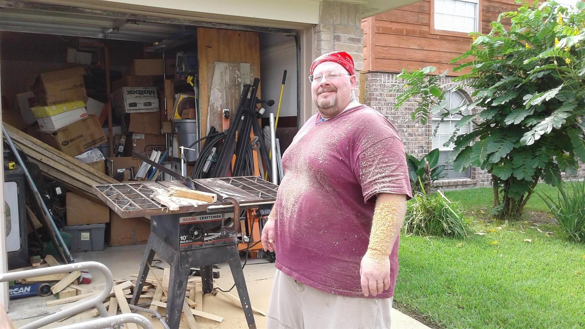
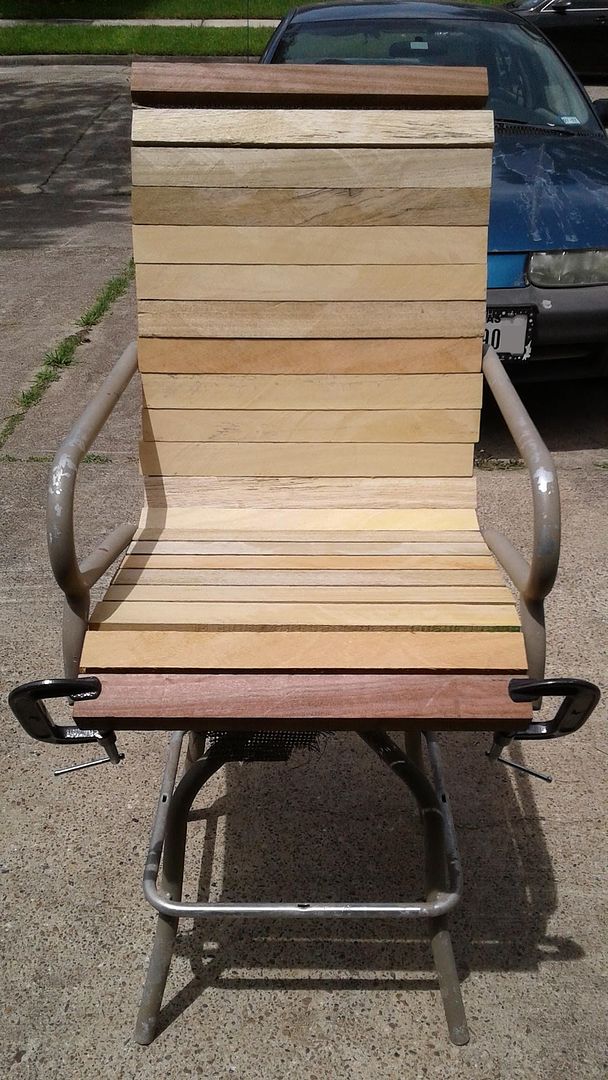


This is my current woodworking project... started last fall after the weather got cool enough for me to breathe, and now stalled for the time being, but still "in the queue". Amusing provenance of this project is that it is literally made entirely of and with "ground score" materiel.

I found the table saw almost complete by the side of the road a few blocks from my house; recognizing the quality I took it home and began restoring it. While I was doing that bit by bit with cheapest possible bits from the internet, I rescued the high chairs, which are actually quite collectible "Space Age" Brown Jordan vintage all aluminum pieces being discarded due to rotted webbing. While researching the "correct" replacement canvas to restore the chairs, I then found several dozen lengths of tropical hardwood 2x2 being discarded from a house renovation/make ready nearby, and decided to put them together into this project.

I have cut all the lumber, including the cedar (?) crown and foot with rollover you see and matching accent slat for the arms and foot rungs. All that remains now is to build a router table so I can finish all the pieces, and I even have a couple of nice Craftsman routers in repairable condition that were given to me by a neighbor who saw me working on the table saw.

I really do need to get back to this and finish it while the nice weather holds out; maybe even bump it up next on my list...


Oh, and to keep this post "TEA-related"; I agree. Simplest solution is to Polish-engineer a separate 5V regulated power supply using an old 12V wall-wart transformer plugged into an extension cord and a 7805 with some filtering, then see how everything behaves running on that; no need to even mod the circuit in the meter until you've done your reality check using that.

Cheers,


mnem
*Morning wood*
« Last Edit: April 16, 2018, 05:11:27 pm by mnementh »
alt-codes work here:  alt-0128 = €  alt-156 = £  alt-0216 = Ø  alt-225 = ß  alt-230 = µ  alt-234 = Ω  alt-236 = ∞  alt-248 = °
 

Offline Cerebus

  • Super Contributor
  • ***
  • Posts: 10576
  • Country: gb
Re: Test Equipment Anonymous (TEA) group therapy thread
« Reply #9387 on: April 16, 2018, 05:14:40 pm »
It seems that for some reason, woodworking is NOT an area where most engineers and e-nerds seem to excel. Or even to be slightly interested, even.

Not all of us, by any means. This is what passes for woodworking in my house:


That was before the final finishing. I got sidetracked by the need to dry-line the living room, which is why you can see the handiwork of Victorian bodgit builders in the background.
« Last Edit: April 16, 2018, 05:18:18 pm by Cerebus »
Anybody got a syringe I can use to squeeze the magic smoke back into this?
 

Offline GreyWoolfe

  • Supporter
  • ****
  • Posts: 3651
  • Country: us
  • NW0LF
Re: Test Equipment Anonymous (TEA) group therapy thread
« Reply #9388 on: April 16, 2018, 05:33:48 pm »
Since med6753 showed off his DIY scope cart, I thought I would show mine.  Mine isn't near as pretty as his was made literally from scraps of wood in the garage.  Only cost was the casters.  To me, it didn't need to be pretty, it just needed to function.  It's also a multitasker as it holds my Ryobi battery chargers.  Yes, those are Chinese take out trays holding my scope probes.  My patch cables are hiding behind them.


« Last Edit: April 16, 2018, 05:46:40 pm by GreyWoolfe »
"Heaven has been described as the place that once you get there all the dogs you ever loved run up to greet you."
 

Offline bd139

  • Super Contributor
  • ***
  • Posts: 23034
  • Country: gb
Re: Test Equipment Anonymous (TEA) group therapy thread
« Reply #9389 on: April 16, 2018, 05:40:59 pm »
Looking at my Ikea crap and shaking my head in shame :)
 

Offline Specmaster

  • Super Contributor
  • ***
  • Posts: 14483
  • Country: gb
Re: Test Equipment Anonymous (TEA) group therapy thread
« Reply #9390 on: April 16, 2018, 09:49:15 pm »
It has all the essentials although if it was mine, I think I'd be tempted to make the rear corners into right angles with 2 more battens just to reinforce the structure as a whole as the scope is a heavy piece of kit to stick on top and I'd sure hate to see anything happen to it. If its only for your eyes, no need to worry about the frills is there?
Who let Murphy in?

Brymen-Fluke-HP-Thurlby-Thander-Tek-Extech-Black Star-GW-Avo-Kyoritsu-Amprobe-ITT-Robin-TTi
 

Offline med6753

  • Super Contributor
  • ***
  • Posts: 11314
  • Country: us
  • Tek nut
Re: Test Equipment Anonymous (TEA) group therapy thread
« Reply #9391 on: April 17, 2018, 01:12:25 am »
Gang, thanks for the compliments on the scope cart (trolley?) but in no way am I a skilled wood worker. My Father had that skill and my Son has that skill. It passed right over me. You would be surprised what a coat of stain and poly will cover up. My wood joinery is simple butt joints which any competent cabinet maker would avoid like the plague. That’s not to say my joints aren’t strong. And overabundance of glue, nails, or screws see to that. I live in an apartment so I don’t have a shop. All my cutting is done outside with hand power tools such as a jig saw. Same with sanding…outside.

I build something out of a specific need because it’s either not available commercially or too expensive. That was the basis for my current bench (1st pix) which I first put together nearly 20 years ago. At that time it was going to be in a living area so it had to be somewhat neat in order to pass the lady of the house test. Today it’s currently in my living room and I try to keep it neat unless I have a project going. But it doesn’t have to answer to the lady because there is none. (Actually there is but she doesn’t live here so has no say).  The laptop stand in that pix was also built by me. To each side are cabinet units from Walmart. Other recent projects were an integration of a media PC with an audio system which resulted in the unit in the 2nd pix. Completely custom to what I wanted.

Finally…TEA content…where do you get those yellow BNC cover plugs? Want! 
An old gray beard with an attitude.
 

Offline Specmaster

  • Super Contributor
  • ***
  • Posts: 14483
  • Country: gb
Re: Test Equipment Anonymous (TEA) group therapy thread
« Reply #9392 on: April 17, 2018, 01:25:12 am »
Well I can't see anything wrong with your woodworking skills looking at those photos, they look every bit as good as factory made cabinets to me.  :-+
Who let Murphy in?

Brymen-Fluke-HP-Thurlby-Thander-Tek-Extech-Black Star-GW-Avo-Kyoritsu-Amprobe-ITT-Robin-TTi
 
The following users thanked this post: med6753

Offline rhb

  • Super Contributor
  • ***
  • Posts: 3483
  • Country: us
Re: Test Equipment Anonymous (TEA) group therapy thread
« Reply #9393 on: April 17, 2018, 03:35:01 am »
It seems that for some reason, woodworking is NOT an area where most engineers and e-nerds seem to excel. Or even to be slightly interested, even.

Not all of us, by any means. This is what passes for woodworking in my house:


That was before the final finishing. I got sidetracked by the need to dry-line the living room, which is why you can see the handiwork of Victorian bodgit builders in the background.

looks as if it gets played quite a lot.  Very nice. Might need a fret job before it gets finished though.
 

Offline Cerebus

  • Super Contributor
  • ***
  • Posts: 10576
  • Country: gb
Re: Test Equipment Anonymous (TEA) group therapy thread
« Reply #9394 on: April 17, 2018, 04:54:57 am »
looks as if it gets played quite a lot.  Very nice. Might need a fret job before it gets finished though.

That was quite a long time ago, I just haven't got around to taking any photos of it truly finished. It got built, a wash coat of shellac just to seal everything and a half hearted french polish and then it got played in a bit before I did the finishing properly - just in case any major adjustments were needed. I was lucky, it settled in nicely and nothing needed doing beyond applying the finishing touches.

It looks well played there just because it hadn't had the full lacquer, fretboard oiled and frets fully levelled at that stage. It's now about 17 years old and now does look well played - I've almost worn the finish off where my right arm rests. In fact it's time to strip the lacquer, reset the neck a tiny fraction and re-do the finish again. I'm still a little amazed that I started with a few bits of flat wood and a reel of fretwire and ended up with a guitar. I had scant woodworking experience when I started, and by the time I'd finished any other woodworking job (short of carving) no longer held any fears for me. I've got some cocobolo back and sides waiting to be turned into a 0000 when I can find the time (and the patience, cocobolo is not an easy wood to work with) and have enough brownie points in hand with SWMBO to permit filling the house with wood shavings.
Anybody got a syringe I can use to squeeze the magic smoke back into this?
 

Offline VK5RC

  • Supporter
  • ****
  • Posts: 2672
  • Country: au
Re: Test Equipment Anonymous (TEA) group therapy thread
« Reply #9395 on: April 17, 2018, 12:16:16 pm »
I don't know if it counts as woodworking, but ship modelling needs a lathe and a 3 inch long plane so I sort of think it does count.
Took me about 2 years - working 1-2 hrs 3-4x/week (while the kids were asleep). Hardest parts are planking the hull (each plank laid individually & boring) and the knot tying (so many knots and fiddly). Completed in about 2003. It is one of the few hobbies where drinking alcohol actually helps (reduces tremor) :-+
Dimensions L~700mm, H~500mm, W~250mm, Wt ~1kg
Apologies for the photo - but it is in a glass case and hard to get out.
Whoah! Watch where that landed we might need it later.
 

Offline Specmaster

  • Super Contributor
  • ***
  • Posts: 14483
  • Country: gb
Re: Test Equipment Anonymous (TEA) group therapy thread
« Reply #9396 on: April 17, 2018, 12:19:51 pm »
I don't know if it counts as woodworking, but ship modelling needs a lathe and a 3 inch long plane so I sort of think it does count.
Took me about 2 years - working 1-2 hrs 3-4x/week (while the kids were asleep). Hardest parts are planking the hull (each plank laid individually & boring) and the knot tying (so many knots and fiddly). Completed in about 2003. It is one of the few hobbies where drinking alcohol actually helps (reduces tremor) :-+
Dimensions L~700mm, H~500mm, W~250mm, Wt ~1kg
Apologies for the photo - but it is in a glass case and hard to get out.
That's beautiful and it more than counts in my opinion [emoji106]

From mobile device so predictive text might have struck again [emoji83]

Who let Murphy in?

Brymen-Fluke-HP-Thurlby-Thander-Tek-Extech-Black Star-GW-Avo-Kyoritsu-Amprobe-ITT-Robin-TTi
 
The following users thanked this post: VK5RC

Offline med6753

  • Super Contributor
  • ***
  • Posts: 11314
  • Country: us
  • Tek nut
Re: Test Equipment Anonymous (TEA) group therapy thread
« Reply #9397 on: April 17, 2018, 12:26:40 pm »
I don't know if it counts as woodworking, but ship modelling needs a lathe and a 3 inch long plane so I sort of think it does count.
Took me about 2 years - working 1-2 hrs 3-4x/week (while the kids were asleep). Hardest parts are planking the hull (each plank laid individually & boring) and the knot tying (so many knots and fiddly). Completed in about 2003. It is one of the few hobbies where drinking alcohol actually helps (reduces tremor) :-+
Dimensions L~700mm, H~500mm, W~250mm, Wt ~1kg
Apologies for the photo - but it is in a glass case and hard to get out.
That's beautiful and it more than counts in my opinion [emoji106]

From mobile device so predictive text might have struck again [emoji83]

Agreed! That is beautiful! Nice work!  :-+
An old gray beard with an attitude.
 

Offline rhb

  • Super Contributor
  • ***
  • Posts: 3483
  • Country: us
Re: Test Equipment Anonymous (TEA) group therapy thread
« Reply #9398 on: April 17, 2018, 01:37:58 pm »
An absolutely spectacular model.  One of the things I find so delightful about eevblog is the wide range of skills and interests.  I play guitar and want to build one.  This has gone on for 40 years.   I bought wooda few years back, but haven't gotten the shop in order to where I can start.  One can have too many toys.  I got sucked in to metalworking for quite a while and acquired a lathe, mill, welder, etc.  I'm only now scratching the test equipment itch again after a 20 year hiatus.

The ship model, like the guitar are made of wood, but the skill level is so much higher that calling it "woodworking" would be somewhat insulting.
 

Offline bd139

  • Super Contributor
  • ***
  • Posts: 23034
  • Country: gb
Re: Test Equipment Anonymous (TEA) group therapy thread
« Reply #9399 on: April 17, 2018, 02:19:16 pm »
I think the thing is that certain subjects attract intelligent, creative people and many of us have different outlets for that creativity. I see very few people sitting there consuming crap from the television by default (the flat sucker of life) and rotting away. So many better things to do. It's good  :-+


Share me

Digg  Facebook  SlashDot  Delicious  Technorati  Twitter  Google  Yahoo
Smf