Author Topic: Quickly, accurately, repeatably measuring xtal/osc frequency  (Read 79109 times)

0 Members and 1 Guest are viewing this topic.

Offline whateverTopic starter

  • Contributor
  • !
  • Posts: 45
  • Country: us
Quickly, accurately, repeatably measuring xtal/osc frequency
« on: January 08, 2024, 05:33:57 am »
Say I have to measure several dozen 2-pin xtal cans, 4.00 Mhz to 80.00 Mhz. They need to be checked for accuracy. All are hot-swappable in a 5v based DIY driver ckt. (see photo). This works very well.
But where I run into weird issues is when the same xtal is in the ckt they are intended to be used. Say an audio D/A, DVD player or CD player. Measurement  in situ , with xtal across an IC's X_in to X_out "driver pins" gives all sorts of distorted or inaccurate readings; perhaps, only the old Tek 465 is most reliable and repeatable for xtals in circuit.
What I have to measure:
I have an old-school but calibrated Tek 465, a modern Siglent 1202x-e dso, NanoVNA, NanaoSA, Owon xdm2041 desktop dmm, and Koolertron DDS sig gen/counter.
Does anyone have preferences?

==================
Test jig:


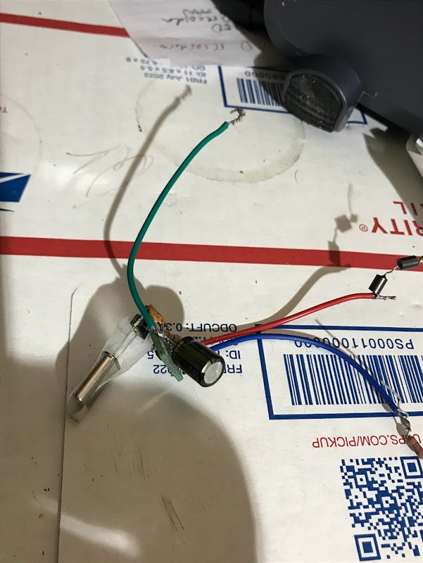
Works well even with simple DDS counter:


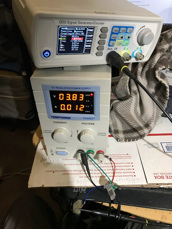
But here's where I run into issues (e.g., measuring in circuit, with xtal driven by microprocessor's X_in/X_out pins. I get no or garbage readings when probing at X_in or X_out -- with dso, dds, dmm, NanoSA, etc):
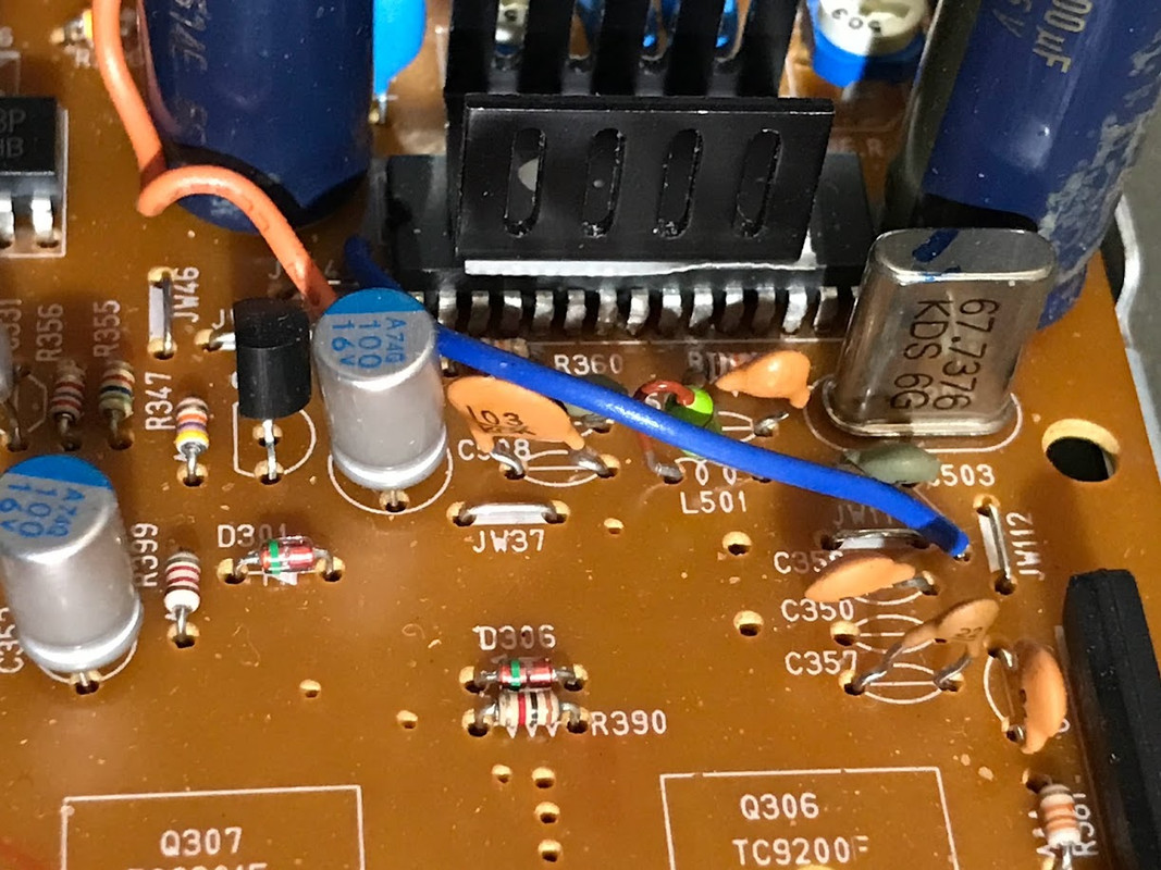
[/url
« Last Edit: January 08, 2024, 05:58:50 am by whatever »
 

Offline Andy Chee

  • Super Contributor
  • ***
  • Posts: 1924
  • Country: au
Re: Quickly, accurately, repeatably measuring xtal/osc frequency
« Reply #1 on: January 08, 2024, 05:59:48 am »
When measuring crystal oscillator circuits in situ, it's extremely easy to disrupt its operation merely by the stray capacitance from directly connecting your probe.

In other words, do not directly connect your probe to the Xtal oscillator, use a small antenna loop (use Dave's trick of connecting the probe alligator back to the probe tip).
 
The following users thanked this post: MathWizard

Offline MathWizard

  • Super Contributor
  • ***
  • Posts: 2483
  • Country: ca
Re: Quickly, accurately, repeatably measuring xtal/osc frequency
« Reply #2 on: January 08, 2024, 07:29:36 am »
So do you mean connect probe GND to probe tip to form a 1 loop inductor, and put it near some oscillator and you will see a little blip on your scope ?

I'm probably mixing that up
« Last Edit: January 08, 2024, 07:33:59 am by MathWizard »
 

Offline Andy Chee

  • Super Contributor
  • ***
  • Posts: 1924
  • Country: au
Re: Quickly, accurately, repeatably measuring xtal/osc frequency
« Reply #3 on: January 08, 2024, 07:50:15 am »
So do you mean connect probe GND to probe tip to form a 1 loop inductor, and put it near some oscillator and you will see a little blip on your scope ?
Pretty much!  Should even be enough length in the ground lead to form a small diameter pickup loop.

Of course, it won't give you any calibrated voltage reading, but it should be enough to sense the operating frequency of a xtal oscillator.
 

Online David Hess

  • Super Contributor
  • ***
  • Posts: 19053
  • Country: us
  • DavidH
Re: Quickly, accurately, repeatably measuring xtal/osc frequency
« Reply #4 on: January 08, 2024, 08:08:46 am »
You should be able to measure the frequency by probing the output of the gate oscillator, but the probe loading still needs to be small, so use a x10 oscilloscope probe.

Get a frequency counter which has a 1 megohm high impedance input like an oscilloscope does, and use a x10 oscilloscope probe with it.  Universal counters usually have these inputs and work up to 100 MHz.  Something like an HP 5314A, HP 5315A, or HP 5316A would be ideal.

Even better, use a low capacitance active probe.  If they are too expensive, then you can make one as shown below.
 

Offline Solder_Junkie

  • Frequent Contributor
  • **
  • Posts: 613
  • Country: gb
Re: Quickly, accurately, repeatably measuring xtal/osc frequency
« Reply #5 on: January 08, 2024, 11:42:02 am »
"Say I have to measure several dozen 2-pin xtal cans, 4.00 Mhz to 80.00 Mhz. They need to be checked for accuracy"

Are you sure? If you are using crystals as basic clock oscillators in equipment the exact frequency doesn't matter. Few of these circuits include a trimmer to set the frequency. Crystals can be "pulled" by up to around 5 KHz by components used in the oscillator circuit.

Old crystals are likely to be slightly off frequency due to ageing. They also might not pull onto frequency. But unless you are using them in filters, transmitters, or frequency counters, just check if they oscillate or not. Even sluggish crystals generally oscillate if the circuit is driving them hard enough.

SJ
 

Offline whateverTopic starter

  • Contributor
  • !
  • Posts: 45
  • Country: us
Re: Quickly, accurately, repeatably measuring xtal/osc frequency
« Reply #6 on: January 08, 2024, 01:39:27 pm »
You should be able to measure the frequency by probing the output of the gate oscillator, but the probe loading still needs to be small, so use a x10 oscilloscope probe.

Get a frequency counter which has a 1 megohm high impedance input like an oscilloscope does, and use a x10 oscilloscope probe with it.  Universal counters usually have these inputs and work up to 100 MHz.  Something like an HP 5314A, HP 5315A, or HP 5316A would be ideal.

Even better, use a low capacitance active probe.  If they are too expensive, then you can make one as shown below.

Just curious: What book is that Figure 2.3 from?

I was wondering if the solution is not as simple as what is shown in Fig. 2. of this document:
https://pdfserv.maximintegrated.com/en/an/AN4949.pdf
 

Offline CaptDon

  • Super Contributor
  • ***
  • Posts: 2571
  • Country: is
Re: Quickly, accurately, repeatably measuring xtal/osc frequency
« Reply #7 on: January 08, 2024, 02:02:25 pm »
It is indeed very true that many L.S.I. integrated circuits have very feeble and easily disturbed Xtal as well as R/C and L/C oscillator circuits. Often these circuits have a CLK output at some divisor of the Xtal frequency and that is where you measure and then multiply the reading if need be. One of the circuits I tested in a QC/QA environment years ago could not be touched by any probe at all. There was a trimmer to set the oscillator at 1MHz exactly + or - 5Hz max. I set a little Sony transistor radio on top of the unit under test tuned to 1MHz and placed some leakage from a very precise 1MHz oscillator nearby. The radio picked up the beat frequency between the two oscillators and allowed me to trim the U.U.T. without probing it. Our best low capacitance probe 'pulled' the oscillator nearly 10KHz. If the circuit was of by 5Hz it could gain or lose about 1 minute in 138 days but I could trim it to within better than 2Hz gaining or losing about 1 minute in a year. It was part of a test instrument which generated tones and had a real time clock for logging. They made wasteful use of the 1MHz oscillator for the R.T.C. as opposed to a simple 32.768KHz arrangement but it was all CMOS so it was still not too harsh on the backup battery.
Collector and repairer of vintage and not so vintage electronic gadgets and test equipment. What's the difference between a pizza and a musician? A pizza can feed a family of four!! Classically trained guitarist. Sound engineer.
 

Offline radiolistener

  • Super Contributor
  • ***
  • Posts: 5618
  • Country: Earth
Re: Quickly, accurately, repeatably measuring xtal/osc frequency
« Reply #8 on: January 08, 2024, 03:09:46 pm »
I think the most easy way is to use some cheap frequency meter from aliexpress and SDR receiver for calibration, you can calibrate your frequency meter with according to standard frequency and time signal radio station available in your region using SDR receiver. Then just put your crystal into simple generator circuit and measure it's frequency with frequency meter...

You can use something like this: https://www.aliexpress.com/item/1005006321816803.html

There is also crystal oscillator frequency meter diy kit: https://www.aliexpress.com/item/32847750953.html
it has less precision, but allows jut to put your oscillator into device and see it's frequency on the display...  :)
 

Online David Hess

  • Super Contributor
  • ***
  • Posts: 19053
  • Country: us
  • DavidH
Re: Quickly, accurately, repeatably measuring xtal/osc frequency
« Reply #9 on: January 08, 2024, 03:58:52 pm »
Quote
Even better, use a low capacitance active probe.  If they are too expensive, then you can make one as shown below.

Just curious: What book is that Figure 2.3 from?

Troubleshooting Analog Circuits by Robert Pease.

Quote
I was wondering if the solution is not as simple as what is shown in Fig. 2. of this document:
https://pdfserv.maximintegrated.com/en/an/AN4949.pdf

I have made the measurement in exactly that way, although without the 200k resistance.  It usually works but as pointed out, may pull the crystal frequency.  In some cases the probe's input capacitance can replace the associated capacitor to ground, or be compensated for.

As CaptDon points out, there may be another spot to probe the divided frequency which will not affect the crystal oscillator.


Offline whateverTopic starter

  • Contributor
  • !
  • Posts: 45
  • Country: us
Re: Quickly, accurately, repeatably measuring xtal/osc frequency
« Reply #10 on: January 08, 2024, 07:13:49 pm »
Yes, probing the X_o / X_in pins of an active device (CD player playing) can cause issues; but those issues are not repeatable.

Below are various diy osc (clock) projects for audiophile experiments. These clocks almost always behave and do not have  aforementioned probing issues while in active (in circuit) use. To replace the OEM xtal with new clock, one simply removes the orig xtal and its caps. Then, the outboard clock is connected to processor (IC) X_in pin; the X_out pin is not used and remains open.


Offline selcuk

  • Frequent Contributor
  • **
  • Posts: 259
  • Country: tr
Re: Quickly, accurately, repeatably measuring xtal/osc frequency
« Reply #11 on: January 08, 2024, 09:24:20 pm »
This is a two-page quick reference about crystal load capacitance. Please check the warning and recommendation about oscilloscope probe on the second page.

https://www.raltron.com/webproducts/technical/technical_notes/RT-DWG-LoadCapConsiderations-1a-final.pdf


Online Wallace Gasiewicz

  • Super Contributor
  • ***
  • Posts: 1571
  • Country: us
Re: Quickly, accurately, repeatably measuring xtal/osc frequency
« Reply #12 on: January 09, 2024, 12:59:28 am »
Capt Don's idea is really cool. And it works.
Your reading of the freq will be only as accurate as the time base of the instrument you are using. Here is a quick way of getting a decent reading. 
Use the most accurate instrument you have,
Put a 10X probe on your Spectrum and put it near the xtal with the ground lead shorted to the tip (Dave's Trick, used by many radio tecks for many years.)Spectrum is more sensitive than the scope almost all the time.For quick checks sometimes I just put the Scope/Spectrum Analyzer probe on the Xtal Case. This works but can disturb the Xtal.
The inputs n a SA will "load" down the circuit more than scope probes if you attach them to the circuit because they are typically 50 ohm inputs rather that thousands of ohms, but they are more sensitive.
As stated "attaching" anything to the osc circuit will probably change the behavior of the xtal even stopping it .There may be a pin on the nearby IC that serves as a "buffer" for the generated xtal freq and would be a good place to actually see the signal. Putting a lead on the Xtal in and out would probably stop the oscillation, since that connects directly to the xtal. Perhaps probe the other leads or find the freq out (clock out) lead of the IC.  That way you are sampling a signal not from the oscillator itself but from an amplifier of that signal.
 

Offline whateverTopic starter

  • Contributor
  • !
  • Posts: 45
  • Country: us
Re: Quickly, accurately, repeatably measuring xtal/osc frequency
« Reply #13 on: January 09, 2024, 02:45:09 am »
Useful feedback to all! Thx!

Yeah, putting a probe on the xtal  pins-- even if those pins have a loaded connection to  IC's X_in and X_out driver pins --is likely the culprit. And why the BCK signal is almost never affected. For CDPs, it's usually a 1.44 Mhz As shown here on my Tek 465:


One of the reasons why audiophile designers like to opt for external clocks - - with a clean, dedicated pwr source of their own -- is so the DAC or digital filter ASICs don't have to multi-task.
« Last Edit: January 09, 2024, 03:07:50 am by whatever »
 

Offline whateverTopic starter

  • Contributor
  • !
  • Posts: 45
  • Country: us
Re: Quickly, accurately, repeatably measuring xtal/osc frequency
« Reply #14 on: January 09, 2024, 08:04:29 am »
One more thing that I should note is that neat little sn74lvc1gx04 shown above,
After tweaking the DS-suggested schematic a little, one gets some very clean waveforms out of this tiny device. It's 'scope performance rivals that of many "audiophile super-clocks". At 5.0 volts, the  sn74lvc1gx04 osc. draws about 20mA. That is not an insignificant current draw. So I can see some advantage in feeding such a clean clock signal into the DAC's X_in pin; hence, taking some pressure off the  DAC's internal pwr ckt.

EDIT: Is the mc12060/61 a better xtal driver?
« Last Edit: January 09, 2024, 09:28:53 pm by whatever »
 

Offline radiolistener

  • Super Contributor
  • ***
  • Posts: 5618
  • Country: Earth
Re: Quickly, accurately, repeatably measuring xtal/osc frequency
« Reply #15 on: January 11, 2024, 12:02:35 am »
One of the reasons why audiophile designers like to opt for external clocks - - with a clean, dedicated pwr source of their own -- is so the DAC or digital filter ASICs don't have to multi-task.

The reason is that DAC SNR depends on it's clock jitter/phase noise and ultra low phase noise oscillator is more expensive. So, they can put more cheap oscillator for economy and option to allow use external oscillator for those who want better dynamic range.
 

Offline whateverTopic starter

  • Contributor
  • !
  • Posts: 45
  • Country: us
Re: Quickly, accurately, repeatably measuring xtal/osc frequency
« Reply #16 on: January 11, 2024, 03:07:13 am »
One of the reasons why audiophile designers like to opt for external clocks - - with a clean, dedicated pwr source of their own -- is so the DAC or digital filter ASICs don't have to multi-task.

The reason is that DAC SNR depends on it's clock jitter/phase noise and ultra low phase noise oscillator is more expensive. So, they can put more cheap oscillator for economy and option to allow use external oscillator for those who want better dynamic range.
Well, theoretically, the XO's that are driven by the ASIC should have the cleanest, shortest path to the circuits in the ASIC that need the XO clock timer.
I consider myself an audiophool. I can (subjectively)  hear the diff. a good, external clock can make. However, when it comes to measurements, I do them. And the simple clocks come up looking as clean as the overbuilt ones. Case in point, the sn74vc1gxo4 driver project I built (see photo).
 

Offline radiolistener

  • Super Contributor
  • ***
  • Posts: 5618
  • Country: Earth
Re: Quickly, accurately, repeatably measuring xtal/osc frequency
« Reply #17 on: January 11, 2024, 03:40:33 am »
Well, theoretically, the XO's that are driven by the ASIC should have the cleanest, shortest path to the circuits in the ASIC that need the XO clock timer.

I don't know about ASIC chips, but FPGA chips have very high phase noise and cannot be used as a low phase noise clock source for high dynamic range ADC/DAC. Usually ADC/DAC is clocked from low phase noise clock source directly, and ASIC/FPGA process the data clocked from the same source through buffer which goal is to isolate clock source from noisy FPGA/ASIC chip.
 

Offline Kim Christensen

  • Super Contributor
  • ***
  • Posts: 1819
  • Country: ca
Re: Quickly, accurately, repeatably measuring xtal/osc frequency
« Reply #18 on: January 11, 2024, 04:56:50 am »
Below are various diy osc (clock) projects for audiophile experiments. These clocks almost always behave and do not have  aforementioned probing issues while in active (in circuit) use. To replace the OEM xtal with new clock, one simply removes the orig xtal and its caps.

The reason for this is because the thing in the can is not just a crystal. It's a TCXO (Temperature compensated crystal oscillator) so you're not probing a crystal at all, but rather the buffered output of an oscillator.


Offline Andy Chee

  • Super Contributor
  • ***
  • Posts: 1924
  • Country: au
Re: Quickly, accurately, repeatably measuring xtal/osc frequency
« Reply #19 on: January 11, 2024, 06:34:21 am »
For reference, Dave also perfomed a teardown of these things

 
The following users thanked this post: whatever

Offline whateverTopic starter

  • Contributor
  • !
  • Posts: 45
  • Country: us
Re: Quickly, accurately, repeatably measuring xtal/osc frequency
« Reply #20 on: January 12, 2024, 07:57:27 am »
BTW ... does anyone have info on how well crystal oscillators tolerate soldering heat?
Seems as if that wafer is in a precise position (gap) ... does it distort with heat? so maybe clipping an alligator heat sink may not be a bad idea? Yes? No?


Offline Andy Chee

  • Super Contributor
  • ***
  • Posts: 1924
  • Country: au
Re: Quickly, accurately, repeatably measuring xtal/osc frequency
« Reply #21 on: January 12, 2024, 10:04:00 am »
Seems as if that wafer is in a precise position (gap)
No.  The crystal frequency is determined by its thickness, not the position of its mounting attachments.

« Last Edit: January 12, 2024, 10:35:07 am by Andy Chee »
 

Offline whateverTopic starter

  • Contributor
  • !
  • Posts: 45
  • Country: us
Re: Quickly, accurately, repeatably measuring xtal/osc frequency
« Reply #22 on: January 12, 2024, 11:02:56 am »
Seems as if that wafer is in a precise position (gap)
No.  The crystal frequency is determined by its thickness, not the position of its mounting attachments.


What does have to do with soldering heat, heat damage/distortion, and temp.effects?

Also: from Wikipedia:
https://en.wikipedia.org/wiki/Crystal_oscillator

" Crystal is the common term used in electronics for the frequency-determining component, a wafer of quartz crystal or ceramic with electrodes connected to it."

"The gap between the electrodes and the resonator act as two small series capacitors, making the crystal less sensitive to circuit influences.


Offline Andy Chee

  • Super Contributor
  • ***
  • Posts: 1924
  • Country: au
Re: Quickly, accurately, repeatably measuring xtal/osc frequency
« Reply #23 on: January 12, 2024, 11:25:25 am »
Seems as if that wafer is in a precise position (gap)
No.  The crystal frequency is determined by its thickness, not the position of its mounting attachments.
What does have to do with soldering heat, heat damage/distortion, and temp.effects?
It tells you that the soldering heat, heat damage/distortion, and temperature effects, must directly affect the crystal wafer to affect frequency.

The physical mounting attachments is not a precision mounting.  It is the thickness of the wafer that is precisely cut and it's the thickness that determines frequency.
 

Offline shapirus

  • Super Contributor
  • ***
  • Posts: 2254
  • Country: ua
Re: Quickly, accurately, repeatably measuring xtal/osc frequency
« Reply #24 on: January 12, 2024, 11:38:10 am »
All are hot-swappable in a 5v based DIY driver ckt. (see photo). This works very well.
Please share schematics, if it's not a secret. I need to build one too :).


Share me

Digg  Facebook  SlashDot  Delicious  Technorati  Twitter  Google  Yahoo
Smf