Author Topic: The LTFLU (aka SZA263) reference zener diode circuit  (Read 199425 times)

0 Members and 3 Guests are viewing this topic.

Offline BU508A

  • Super Contributor
  • ***
  • Posts: 4528
  • Country: de
  • Per aspera ad astra
Re: The LTFLU (aka SZA263) reference zener diode circuit
« Reply #300 on: June 20, 2019, 08:04:19 pm »
Since Frank has mentioned it one or two times that he recommends to use the 732A reference as an example, I've found on KO4BB this nice redrawing of the reference circuit:


The original can be found here:

http://ftb.ko4bb.com/manuals/93.200.148.254/Fluke_732A_Redrafted_schematic_of_reference_circuit_of_voltage_standard.pdf
“Chaos is found in greatest abundance wherever order is being sought. It always defeats order, because it is better organized.”            - Terry Pratchett -
 

Offline Echo88

  • Frequent Contributor
  • **
  • Posts: 826
  • Country: de
Re: The LTFLU (aka SZA263) reference zener diode circuit
« Reply #301 on: June 21, 2019, 10:13:30 am »
Indeed a nicer drawing than the convoluted manual schematic :)

I have a few DH80417B-based refs which are quite old and which i want to TC-adjust. Afaik the reference-collector-resistor needs to be adjusted to get around zero TC. Is that correct or do the other resistors have a significant impact on the TC (Fluke WW, <=1ppm stated)?
I know that Conrad TC-adjusted his 731B, but he didnt recall which resistor/-s he adjusted.
 

Offline Kleinstein

  • Super Contributor
  • ***
  • Posts: 14267
  • Country: de
Re: The LTFLU (aka SZA263) reference zener diode circuit
« Reply #302 on: June 21, 2019, 10:41:53 am »
The collector current is at least the obvious point for adjusting the TC as the effect is predictable.  Doubling the current gives some extra 18 mV BE voltage and some -60 µV/K of additional change or some -10ppm/K.

The main Zener current would also effect the TC, but often one is limited here: to low a current would increase the noise and too much current would make it run hot. How much the zener current changes depends on the details of the zener. Still the current setting resistors need to be stable. The TC of the current setting resistor would have an effect by attenuated by something like 1 K divided by the 10Ohm of zener differential resistance.
The series diodes to the main current path may be useful if the TC is otherwise far off. Expect them to give some +10-20 µV/K for each diode, depending on the output voltage/ current setting resistor.
 

Offline Echo88

  • Frequent Contributor
  • **
  • Posts: 826
  • Country: de
Re: The LTFLU (aka SZA263) reference zener diode circuit
« Reply #303 on: June 21, 2019, 11:00:36 am »
Thanks, was a bit unsure due to the instability of my measurement-setup when substituting the collector-resistor with my resistor-decade. Seems i need it to give more temp-stabilizing time for evenly distributed temp on the pcb. Hope to get it near zero TC without using extra diodes like done in the 3330B-reference
 

Offline TiN

  • Super Contributor
  • ***
  • Posts: 4543
  • Country: ua
    • xDevs.com
Re: The LTFLU (aka SZA263) reference zener diode circuit
« Reply #304 on: June 22, 2019, 01:00:33 am »
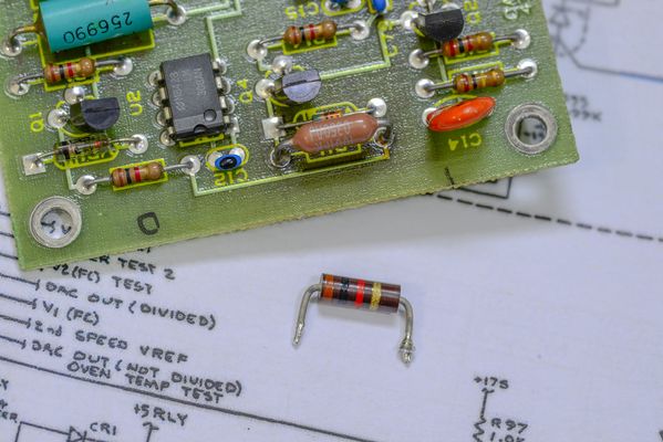
Minor relation, but here are some test results on dual SZA263 reference out of Fluke 5440B board (bought just a board on ebay, to steal a ref).


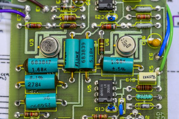
As you can see, board have two Motorola SZA263, year 1982 vintage, some teal epoxy Fluke PWW resistors. There is nothing else to it, no voodoo slots. Ref assembly sits in isothermal oven box on the main DAC/REF PCBA in calibrator. All oven heaters and control circultry is on mainboard, not here.

This module was unexpectedly easy to get working. Just +30 and -15V supply at the input, and +13V DC output, no whackers with external signaling required.
It also maintains output voltage with reduced supply, down to +23V and -1V.


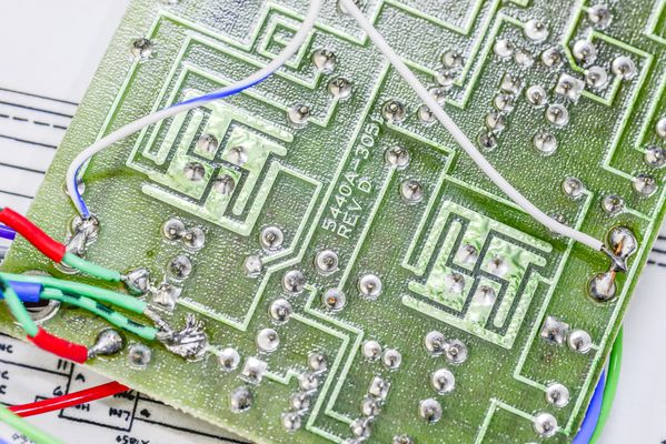
Little trap for young players - Hi sense and Hi force of the output must be connected externally to close the feedback loop.

My love to carbon resistors was rewarded here as well, in shape of R11. Replaced it with 1W metal film 1 Kohm already.  :box:


Magic Fluke shapes around SZA263 chips supposed to keep temperatures uniform among all pins. And it's doing that job just fine.

Colorful picture of the running board as well:


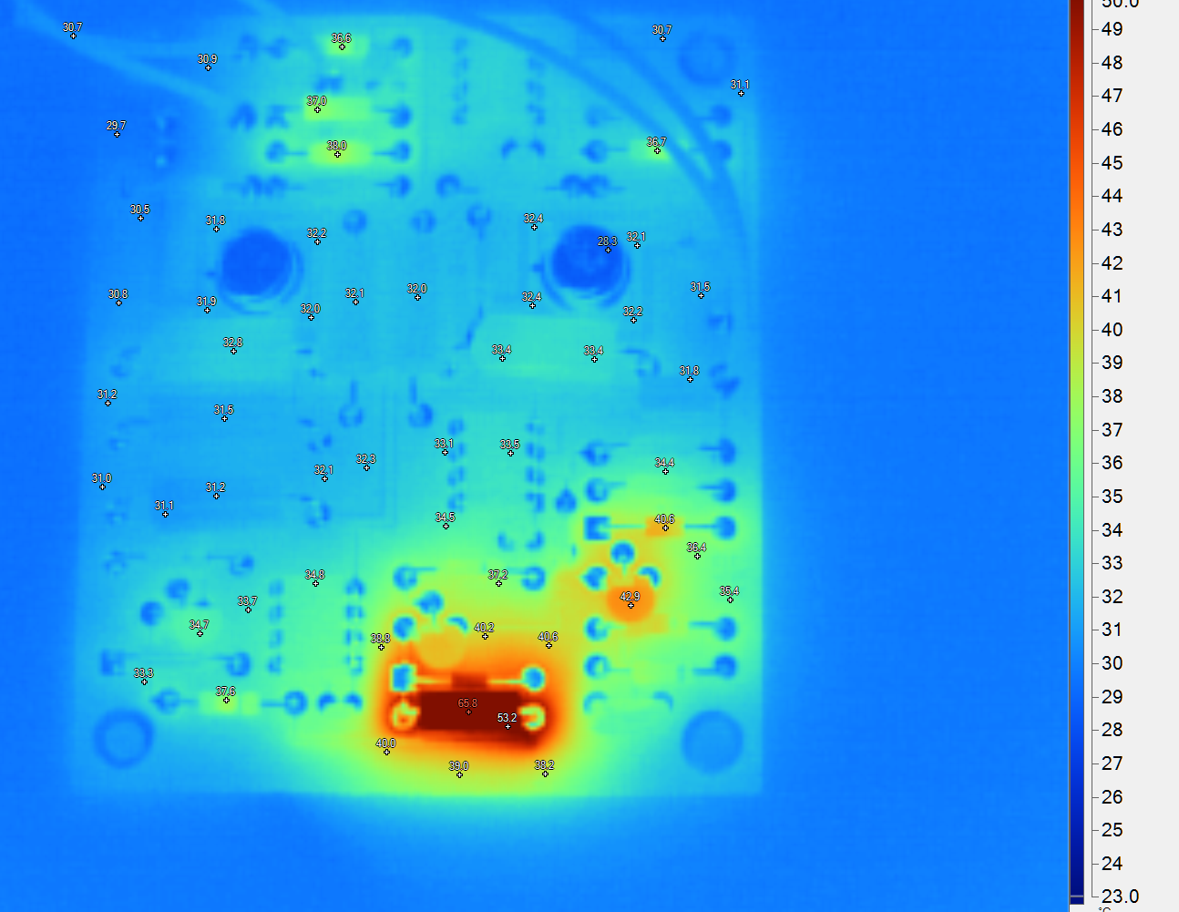
This was taken before replacement of carbon R11 1K resistor.

Results from 8 hour tempco sweep from +18C to +32C:


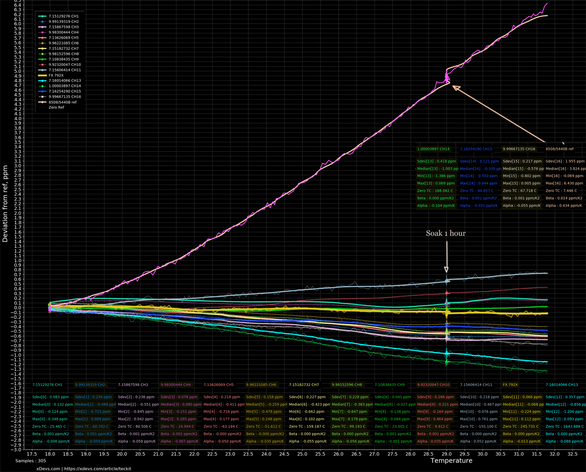
Bunch of lines on other channels are LTZ1000A references.

Overall I'm quite impressed with performance of this cute unheated +13V reference, delivering respectable <0.45 ppm/K. Heck, that is lower than some of LM399's!

Ref was powered by Keysight E36312A benchtop linear PSU, with +25.00 and -12V supply voltages. It took about 24mA for positive rail and ~3mA for negative.

With ovenized assembly, like it is used in Fluke 5440 calibrator there is little to worry about tempco, even if oven temperature kept within easy +/-0.1C.

 RAW-datafile for those who want split ppms.
« Last Edit: June 22, 2019, 01:07:48 am by TiN »
YouTube | Metrology IRC Chat room | Let's share T&M documentation? Upload! No upload limits for firmwares, photos, files.
 
The following users thanked this post: dr.diesel, BU508A, alm

Offline branadic

  • Super Contributor
  • ***
  • Posts: 2393
  • Country: de
  • Sounds like noise
Re: The LTFLU (aka SZA263) reference zener diode circuit
« Reply #305 on: July 01, 2019, 07:00:40 am »
I rearranged LTFLU circuit (RC55Y resistors + LT1006) on my protoboard. I used a NOMCA16035001 resistor network configured to 5k:11k for R7A/R7B. With the current value of 25k343 for R13 I get the following temperature response, with almost zero t.c. at about 32°C. Need to trimm it to 45°C and put it into a 45°C oven. The shape of the curve looks like a typical temperature compensated zener, so no flat temperature response at all. This also explains why Fluke put the reference into an oven, instead of trimming it to zero t.c. over a wide range. Obviously the device I have shows some sort of popcorn noise.

a= -3.077749294582220e-02    b= 1.738680963044457e+00   c= -2.776202459721796e+01

-branadic-
« Last Edit: July 01, 2019, 07:12:49 am by branadic »
Computers exist to solve problems that we wouldn't have without them. AI exists to answer questions, we wouldn't ask without it.
 
The following users thanked this post: Dr. Frank, Sprock

Offline guenthert

  • Frequent Contributor
  • **
  • Posts: 712
  • Country: de
Re: The LTFLU (aka SZA263) reference zener diode circuit
« Reply #306 on: July 01, 2019, 04:28:11 pm »
What happened between 7:30h and 9h in the run?  That's no popcorn noise and doesn't seem temperature related.
 

Offline branadic

  • Super Contributor
  • ***
  • Posts: 2393
  • Country: de
  • Sounds like noise
Re: The LTFLU (aka SZA263) reference zener diode circuit
« Reply #307 on: July 01, 2019, 09:59:38 pm »
I have no idea, I was sleeping during that time :)

-branadic-
Computers exist to solve problems that we wouldn't have without them. AI exists to answer questions, we wouldn't ask without it.
 

Offline branadic

  • Super Contributor
  • ***
  • Posts: 2393
  • Country: de
  • Sounds like noise
Re: The LTFLU (aka SZA263) reference zener diode circuit
« Reply #308 on: July 02, 2019, 07:13:15 am »
So I changed R13 last night by estimating the value required for 45°C (linear correlation expected). I guess I found the correct value, R13 is now 22k. Time to replace the decade resistor box by a proper resistance and repeat the measurement.
Next step is to adjust 10,00000V output and add an LDO, as by now the circuit is powered from a linear lab power supply directly (15V). Afterwards I need to build an oven around the reference.

-branadic-
Computers exist to solve problems that we wouldn't have without them. AI exists to answer questions, we wouldn't ask without it.
 

Offline Dr. Frank

  • Super Contributor
  • ***
  • Posts: 2385
  • Country: de
Re: The LTFLU (aka SZA263) reference zener diode circuit
« Reply #309 on: July 02, 2019, 09:49:46 am »
..
The shape of the curve looks like a typical temperature compensated zener, so no flat temperature response at all. This also explains why Fluke put the reference into an oven, instead of trimming it to zero t.c. over a wide range.

-branadic-

Hello branadic ,

I think you have demonstrated, that the RefAmp can never be trimmed to zero  over a broad temperature range, but only at a single temperature point!
The 731B has a specified T.C. of < 1ppm/K over 10..45°C , and that fits perfectly to your measurement.. so nothing more can be expected, anyhow.

If you put this pre-T.C.-trimmed circuit into an oven, the stability requirements on the oven will be much less demanding compared to that 50ppm/K T.C. of the LTZ1000, I assume.

Could you please provide your calculus, how you estimated the correct R13 value for 45°C from the initial 25k set up?

Maybe it's sufficient to add an oven around the LTFLU, like it's done in the 335D reference assemblies (with the SZA or DH80... chips) ?

THX - Frank
« Last Edit: July 02, 2019, 09:52:49 am by Dr. Frank »
 

Offline branadic

  • Super Contributor
  • ***
  • Posts: 2393
  • Country: de
  • Sounds like noise
Re: The LTFLU (aka SZA263) reference zener diode circuit
« Reply #310 on: July 02, 2019, 10:03:33 am »
Hi Frank,

I simply had two temperature runs with two different resistor values and zero t.c. point close to 30°C (25k343) and 35°C (24k), so I assumed a linear correlation to estimate the resistor value for 45°C (22k) and that seemed to work.
I was planing an oven circuit as used in 732B based on TL062, but with a setup as used in Fluke calibrators, thus a single sided ceramic, with a ceramic thickfilm heater (in my case BPR10101) glued to its back. First successful processed ceramic samples are on my desk.

-branadic-
Computers exist to solve problems that we wouldn't have without them. AI exists to answer questions, we wouldn't ask without it.
 
The following users thanked this post: TiN, Dr. Frank

Offline Echo88

  • Frequent Contributor
  • **
  • Posts: 826
  • Country: de
Re: The LTFLU (aka SZA263) reference zener diode circuit
« Reply #311 on: July 02, 2019, 12:24:49 pm »
Are there still suitable small ovens available like the ones made by Klixon, which only heat the Refamp-Chip?
 

Offline chuckb

  • Frequent Contributor
  • **
  • Posts: 342
  • Country: us
Re: The LTFLU (aka SZA263) reference zener diode circuit
« Reply #312 on: July 02, 2019, 05:29:23 pm »
I simply had two temperature runs with two different resistor values and zero t.c. point close to 30°C (25k343) and 35°C (24k), so I assumed a linear correlation to estimate the resistor value for 45°C (22k) and that seemed to work.
-branadic-

A glass thermistor / precision resistor network that provided 25k343 ohm at 30 deg C and 22k at 45 deg C could flatten the temp co curve of the reference. This would be useful for low power applications.
This is similar to what lymex proposed for flattening the temp co curve of precision resistors. Good quality glass thermistors can have very good stability.

Of course you may want an oven to help stabilize the resistors in the 7V to 10V stage, reduce relative humidity and minimize hysteresis.
 

Online Andreas

  • Super Contributor
  • ***
  • Posts: 3252
  • Country: de
Re: The LTFLU (aka SZA263) reference zener diode circuit
« Reply #313 on: July 02, 2019, 06:54:45 pm »
Next step is to adjust 10,00000V output and add an LDO,

interesting would be determing the PSRR before stabilizing the voltage.

with best regards

Andreas
 

Offline Echo88

  • Frequent Contributor
  • **
  • Posts: 826
  • Country: de
Re: The LTFLU (aka SZA263) reference zener diode circuit
« Reply #314 on: July 04, 2019, 01:29:28 am »
Lymex mentioned the possibility of substituting the R1/2 (main-divider without stability-attenuation)-divider in the usual RefAmp-circuit with a LTC1043.
So i tried to simulate it with the 731B-circuit as the basis and it works.
LTC1043-blocks are used as /3 and *2 to get ~10V.
The calculation is as follows: Ub (6.807V) /2 *3 =  Vout (10.210V).
Outputvoltage ~10.210V, sadly a bit more then the wanted 10V +-100mV to measure references in opposition mode with a DMM in 100mV-range.
Have to read the thread again for info on real measured usual Ub @ 3mA Iz and ~100µA Ic.
Simulation in LTSpice is attached. Also the minimized version which uses only 1 LTC1043 as /3*2-divider from Andreas.

What i still dont get is the exact control loop of the RefAmp-circuit and why it attenuates some resistor-variations. For example i dont know why the resistor-divider (R28/19 in the simulation) doesnt massively influence the outputvoltage. Maybe someone can explain it to me?
« Last Edit: July 06, 2019, 12:31:26 pm by Echo88 »
 

Offline Kleinstein

  • Super Contributor
  • ***
  • Posts: 14267
  • Country: de
Re: The LTFLU (aka SZA263) reference zener diode circuit
« Reply #315 on: July 04, 2019, 03:20:15 pm »
The R28/R19  divider (together with the main divider) sets the emitter-collector voltage for the transistor in the reference. This voltage only has a limited effect on the gain of the transistor stage.  Similar R32 set the current for the transistor stage and this way on a logarithmic scale a small contribution to the V_BE part of the reference voltage.

The transistor stage has a gain of around 100, that is about set by the voltage at R32 (slightly reduced by the Early effect) divided by kT/e.
Changes in R32, R28, R19 are about attenuated by this factor, so that changes of these resistors are less critical. The capacitor C2 reduces the gain of the transistor stage towards higher frequencies to ensure stability of the OPs FB loop. So the low frequency range (up to a few 10-100 Hz) is dominated by the transistor in the reference, while the higher frequency part is mainly controlled by the OP and C2 acts as low pass filter for the reference part.

For reducing the output voltage, one could modify the FB divider to also use a small resistive contribution (e.g. have the divider from V_out to the the buffer LT1012 output) to go to the transistor. As the part effected by these transistors is only small (e.g. 200 mV instead of some 3.5 V), stability of these transistors would be less critical than a full divider by about a factor of 20. This is still a little more critical than the other resistors (R32, R28,R19), but not that much.

There may be a better version for the LTC1043 divider that directly gives 2/3 in a single stage, a little like the 1/3 stage.
 

Online Andreas

  • Super Contributor
  • ***
  • Posts: 3252
  • Country: de
Re: The LTFLU (aka SZA263) reference zener diode circuit
« Reply #316 on: July 04, 2019, 07:36:08 pm »
LTC1043-blocks are used as /3 and *2 to get ~10V.

Hello,

there is also a possibility to do this with one single LTC1043: (and without extra measures to synchronize the clocks).
https://www.eevblog.com/forum/projects/building-a-7-decade-voltage-calibrator/msg298350/#msg298350

With best regards

Andreas
 

Offline Echo88

  • Frequent Contributor
  • **
  • Posts: 826
  • Country: de
Re: The LTFLU (aka SZA263) reference zener diode circuit
« Reply #317 on: July 04, 2019, 09:37:18 pm »
I can only find the /2*3 and *3/4-implementation in the thread. Do you have the /3*2, so i can implement it in the simulation?
 

Online Andreas

  • Super Contributor
  • ***
  • Posts: 3252
  • Country: de
« Last Edit: July 05, 2019, 06:39:06 pm by Andreas »
 

Offline Echo88

  • Frequent Contributor
  • **
  • Posts: 826
  • Country: de
Re: The LTFLU (aka SZA263) reference zener diode circuit
« Reply #319 on: July 06, 2019, 01:07:09 am »
Thanks, RefAmp-circuit with minimalized /3*2-circuit added to the post from me above.
 
The following users thanked this post: Andreas

Offline branadic

  • Super Contributor
  • ***
  • Posts: 2393
  • Country: de
  • Sounds like noise
Re: The LTFLU (aka SZA263) reference zener diode circuit
« Reply #320 on: July 06, 2019, 10:31:20 am »
So here is a picture of my current LTFLU protoboard. I can hear them voices "Don't use sockets, sockets are bad!", but I did since it's only for verification and not the final board. More to come soon, hopefully.

-branadic-
« Last Edit: July 06, 2019, 01:34:18 pm by branadic »
Computers exist to solve problems that we wouldn't have without them. AI exists to answer questions, we wouldn't ask without it.
 
The following users thanked this post: TiN

Offline TiN

  • Super Contributor
  • ***
  • Posts: 4543
  • Country: ua
    • xDevs.com
Re: The LTFLU (aka SZA263) reference zener diode circuit
« Reply #321 on: July 08, 2019, 04:05:39 am »
The sockets are fine, the leads with gator clips are however...  :popcorn:
I usually just solder twinax wire or shielded UTP cable during test, so i can mangle with the board without worry about value changing because of connection to DUT.
YouTube | Metrology IRC Chat room | Let's share T&M documentation? Upload! No upload limits for firmwares, photos, files.
 

Offline branadic

  • Super Contributor
  • ***
  • Posts: 2393
  • Country: de
  • Sounds like noise
Re: The LTFLU (aka SZA263) reference zener diode circuit
« Reply #322 on: July 13, 2019, 07:31:04 pm »
Modified circuit today, LTFLU is know running from single 12V supply and decade resistor box was replaced by fixed resistors. Though the output is not proper adjusted to 10,00000V yet readings are now stable.
So I'm on track with the idea to power reference and oven from battery (12x NiMh) with LT1763 LDO set to 12V. Propably I use BMON designed by Andreas or parts of the circuit for a stand-alone reference. The oven circuit will be a copy of Fluke 732B, but with AD822 instead of TL062.

-branadic-
« Last Edit: July 13, 2019, 08:20:53 pm by branadic »
Computers exist to solve problems that we wouldn't have without them. AI exists to answer questions, we wouldn't ask without it.
 
The following users thanked this post: Andreas, chuckb

Online dietert1

  • Super Contributor
  • ***
  • Posts: 2091
  • Country: br
    • CADT Homepage
Re: The LTFLU (aka SZA263) reference zener diode circuit
« Reply #323 on: July 25, 2019, 07:26:59 am »
After i made a LTFLU reference circuit i got a first TC determination. The result is way off, needs adjustment first. This made me think a little.

This type of reference (also the LTZ1000) includes a voltage sensing transistor on chip. If i assume about -2 mV/K as the Ube contribution of that transistor, this amounts to -0.002 V / 7 V * 1E-6 = -286 ppm/K. Is that correct? This terrible TC is there even after compensation by a positive TC of the zener of similar size. So to get the reference down to TC < 0.1 ppm/K, one needs a factor 3000. If the TC compensation is adjusted to 1 %, the oven still needs an ambient temperature regulation of 1/30, that is  < 30 mK/K(ambient) or so.

I know the LTZ1000 thermostat is very fast and oscillates at about 50 Hz if you have enough gain. So speed may be important. On the other hand i remember reading in this forum someone was using water to attach "thermal mass", with very interesting results. Arroyo TEC controllers appear to reach stability levels of some mK, too. What is a practical solution for the LTFLU?

Regards, Dieter
 

Offline Kleinstein

  • Super Contributor
  • ***
  • Posts: 14267
  • Country: de
Re: The LTFLU (aka SZA263) reference zener diode circuit
« Reply #324 on: July 25, 2019, 09:12:21 am »
The TC adjustment can be quite good, better than 1% if needed. It just takes times and effort to find the right transistor current.
Even with a crude oven this would be needed only for the linear TC at the set temperature, no longer over a larger range including square parts.

A temperature regulation to 30 mK/K is not that demanding. A fast loop makes things a little easier, but is not absolutely needed. Extra thermal mass is a two sided thing and may help if the regulator is slow - I prefer good thermal conduction, so that one has only 1 temperature to worry about and not also gradients.

I would start with the oven and than adjust the TC of the reference to the required level for given oven quality. So a better TC adjustment could compensate for a not so well done oven. So the 30 mK/K would be a staring target. 


Share me

Digg  Facebook  SlashDot  Delicious  Technorati  Twitter  Google  Yahoo
Smf