-
I am pretty sure the polarity shown here decodes high voltage as a 1 and low voltage as a 0 - which I'm betting is the predominant convention for RS232.
Likewise, I'm pretty confident that the Decimal decoder gets it right with a LSB sequence - which happens to be what was orginally specified for ASCII.
So, I'm thinking that when Rigol made the Binary decoder for RS232 they should have made the 1s and 0s align with the waveform (as they clearly did and can) but by using LSB instead of MSB. This would create consistency (and possibly correctness.)
Again, I could be wrong and probably am - let me know, and why. Thx, EF
-
In my experience with RS-232, on the wire, a logical low is usually represented as high voltage and logical high as low voltage.
This is always true, for RS232.QuoteIn the screendump below, you can see almost 3 cycles where I captured 0x55, 0x00, 0xFF (being repeated) at 8N1.
I don't think so. Looks like <0x55, 0xFF, 0x00> to me. -
Bummer, I can sort of explain the 21, but I am having a hard time with the 121. This stuff can make your head hurt.


-
So, without further ado I hooked up a PC with up my favorite HyperTerminal ASCII file consisting of all upper case Us so that I could observe some 1s and 0s. (Thanks again to ALM for turning me on to the extra nice square wave pattern generated with the capital Us.)
Yeah, IMO that's the worst possible test value you could have chosen. Why? Because if you manage to generate a stream of back-to-back U's with no timing gaps, what you get is really a square wave! You literally cannot detect where one character frame ends and the next one starts. It's clever, but why would you want to use that to test your understanding of a serial data stream?
Start with something simplistic, like a 0x01 value. That way, the Start and End bits will be more visible, the character frame will be obvious, and you will immediately see that: a) the bit polarity of RS232 data is inverted, and b) the bits are sent out in LSB order. I.e., it's "upside down, and ass-backwards". -
Bummer, I can sort of explain the 21, but I am having a hard time with the 121. This stuff can make your head hurt.
A big part of your problem is that you're trying to figure out a dozen different things at the same time (IMO). Focus on one at a time, then cross that off your list and move on to the next.
E.g., you're going through convolutions to try and get the decoded frame boxes to line up exactly with the data stream. But who knows what algorithm Rigol is using there? Left-alignment, centering, what? Based on your mish-mash of config settings (some most certainly wrong) trying to make things look the way you think they should, I'm not ready to form any conclusions on Rigol alignment yet.
[And yes, I agree that the decode boxes should line up with the start and end of the frame for the bit stream. When they can fit on screen at least.] -
I wrote:
Start with something simplistic, like a 0x01 value. That way, the Start and End bits will be more visible, the character frame will be obvious, and you will immediately see that: a) the bit polarity of RS232 data is inverted, and b) the bits are sent out in LSB order. I.e., it's "upside down, and ass-backwards".
In a bit more detail, what you'll see on screen then will be a leading negative voltage, in the Idle state. The Start bit will go positive for one bit cell. Since the data bits are clocked out backwards (0b10000000), next will be the 1-bit, which will be negative. The remaining seven 0-bits will go positive. And the frame will be terminated with the Stop bit going negative again. It will stay negative (Idle) unless/until additional characters are sent.
Until you get your Config settings on the Rigol set properly to reflect that reality, you're going to be confused and spinning your wheels. -
I appreciate the support from a no doubt considerable distance, really
Let's regroup on a few basics. My HyperTermnal program specifies 8 data bits, 1 stop, no parity, and there is no mention of a start bit. (Earlier in my career I saw examples of 7 or 8 data bits sandwiched between a start bit and a stop bit, plus a parity bit, so I get that it is possible.) In my current setup it isn't clear there is a start bit.
Nonetheless, are you pretty sure I have a start bit in front of each byte? Either way, as far as I can tell, there is no way on the 1000Z to designate a start bit (or any number of start bits). So it's either automatically assumed and inserted or there is no start bit. Only stop bits and parity bits and data bits can be set on the 1000Z.
Frankly, the only thing that I have really focused hard on is finding any combination of the variables that I have to work with that gets the waveform to synchronize with the 1s and 0s - which I have accomplished and which only seems to work with one combination of settings. (I'm pretty/very sure that I have 8 data bits, 1 stop bit and no parity. So mostly what is left is polarity and MSB/LSB settings.
Take a look at the last image I posted - it really isn't very far off from what is expected and to be square we've heard from users here who bailed out on Rigol scopes because they found errors in the decoder.
So I think you can assume that while there is a good chance I haven't got all the setting right, there is also a chance (until you get your hands on a 1000Z) that there might be something in need of a firmware adjustment.
I agree, we don't know what Rigol intended, but again, look at the last image and you will see that the image shows what strikingly looks like a high degree of symmetry and alignment between the binary code and the waveform. Obviously the viewing is limited by what practically fits on the screen, but the last image has what looks like five full bytes.
Also, while the U isn't everyone's favorite, if you notice there were a few other characters in the mix - and again, the waveform spacing and the various strings of 1s and 0s appeared to line up. Plus the three Us decoded as 85s. Additionally, check out spacing directly above the 3 consecutive 0's and the 4 consecutive 1's - I don't think it's all that far off. In fact, I can't see any discrepancies between the waveform and the 1s and 0s.
I'll see if I can get some other characters going - or feel free to post a specific repeating string you like and I'll give it a try. (The capital Us were something that was picked because they make uniform waveforms and earlier on with my analog scope I was just trying to find the signal to trigger on - I think my problem at that stage was that I had flow control on; when that came off the signal was easier to find/trigger. So it's just a project legacy thing.) So far, I've been more focused on ASCII, binary, and decimal than hex.
Net, net: it might look like I was trying a lot of different stuff - I was - but it was with more than just trial and error, it was with a process of elimnation by isolating variables one at a time. There really aren't all that many here and they can all be tested in one or more ways. The main hypothesis that I've held onto that I can't prove is that the 1's and 0's should line up consistently with the the waveform. If that isn't correct I'm inclined to be less interested in the whole thing. If it is correct, then I think it should be a relatively small step to get the ASCII, Hex, and Decimal values to decode properly - and if one green box with Binary can line up with the waveforms, they all can. The process of not only decoding but also aligning the various attributes is both elegant and doable in my book.
Thx again for the help.
-
My HyperTermnal program specifies 8 data bits, 1 stop, no parity, and there is no mention of a start bit. (Earlier in my career I saw examples of 7 or 8 data bits sandwiched between a start bit and a stop bit, plus a parity bit, so I get that it is possible.) In my current setup it isn't clear there is a start bit.
No, I'm not pretty sure. I'm absolutely and unequivocally positive.
Nonetheless, are you pretty sure I have a start bit in front of each byte?
Think about it a sec. You're sitting there Idling, with no characters being transmitted. Your voltage level is at, say, -5V. Then you send out a byte, let's say it's FF, which will also have all bits negative voltages. With no start bit, nothing happens. Then you have the Stop bit, which also goes negative. So nothing at all happened when you sent out an FF? Illogical.
RS232 isn't self-clocking, so you need to have a framework around the data-frame in the bitstream. The Start and Stop bit provide that framework. (And the reason you paid attention to the Stop bits is because there could be 1 or 2. And parity could be Even, Odd, or None. So you had to pick, and get those options right. But there's never anything to decide with the Start bit. It's always there, and always 1 bit long.)QuoteFrankly, the only thing that I have really focused hard on is finding any combination of the variables that I have to work with that gets the waveform to synchronize with the 1s and 0s - which I have accomplished and which only seems to work with one combination of settings. (I'm pretty/very sure that I have 8 data bits, 1 stop bit and no parity. So mostly what is left is polarity and MSB/LSB settings.
Yes, I understand. Part of the reason that an 0x55 is a bad choice is it's symmetry. What happens if you mis-set the polarity, AND the endianism in your Config? Uh, it winds up being still an 0x55, sort of, due to the double inversion.Quote...to be square we've heard from users here who bailed out on Rigol scopes because they found errors in the decoder.
I never suggested otherwise. I wasn't attempting to defend the Rigol... there could be numerous issues. I'm just saying that until you get your ducks in a row that the oddities you're seeing cannot be sorted out. If you do something wrong, the results are going to be wrong, even if the Rigol is right. If you do everything right, then things could still be wrong... but in that case you then know it's an issue with the Rigol. Comprendo?
So I think you can assume that while there is a good chance I haven't got all the setting right, there is also a chance (until you get your hands on a 1000Z) that there might be something in need of a firmware adjustment.Quote...but again, look at the last image and you will see that the image shows what strikingly looks like a high degree of symmetry and alignment between the binary code and the waveform. Obviously the viewing is limited by what practically fits on the screen, but the last image has what looks like 3 full bytes.
Yes, but what I was trying to point out is that you achieved that by mis-setting the Config options.QuoteI'll see if I can get some other characters going - or feel free to post a specific repeating string you like and I'll give it a try.
As I mentioned above, just a string of simple 0x01's (decimal 1's, binary 0b00000001's) would provide a distinctive and unambiguous pattern. There are certainly others, but that's one where I described the exact on screen voltage pattern that corresponded to it.QuoteThx again for the help.
No problemo. I'm glad to see you digging into it. Just sorry to see you getting hung up on RS232, which seems a lot simpler (at the logical level) than it really is (at the physical level). E.g., while TX and Rx are inverted, the Control lines (RTS, CTS, DTR, DSR, etc.) are not. Once you get on the other side of the line-driver, your levels aren't shifted any more, and the bit polarities aren't inverted. They're still LSB though.
Someone else suggested you read up on a reference book on RS232, but you may get enough from Wikipedia to clarify a few things. Jump down to the section on Voltage Levels, and check out the picture there...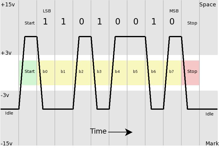
-
Mark_O,
Cool post above, thanks again.
I think we are going to get there. Thanks for the patience and persistence. I appreciate it.
Small correction - while you were posting I edited my previous post to say there were 5 rather than 3 bytes visible in the last image.
Ok, I'll buy in that there is always a start bit, but to reconfirm regarding the 1000Z it must be hard coded in some covnentional manner because there isn't anyway in the menu to specifiy anything regarding the start bit. Perhaps we are seeing the start bit and the stop bit in between each green data bit box?
I need to get my head around this:
"E.g., while TX and Rx are inverted, the Control lines (RTS, CTS, DTR, DSR, etc.) are not. Once you get on the other side of the line-driver, your levels aren't shifted any more, and the bit polarities aren't inverted. They're still LSB though"
Are you saying that some of the 1s and 0s in my image might be RTS, CTS, DSR, etc.? If so, where would they be relative to the data bits and their corresponding waveforms? Is it possible that the decoder ignores the Control Lines and/or drops those bits on the floor? (Or perhaps since what I have caught on the scope is just a text file full of mostly Us rather than an actual one-way or two-way transmission between computers there were no Control Line bits at all?)
Thanks, EF
-
I need to get my head around this:
"E.g., while TX and Rx are inverted, the Control lines (RTS, CTS, DTR, DSR, etc.) are not. Once you get on the other side of the line-driver, your levels aren't shifted any more, and the bit polarities aren't inverted. They're still LSB though"
Are you saying that some of the 1s and 0s in my image might be RTS, CTS, DSR, etc.? If so, where would they be relative to the data bits and their corresponding waveforms? Is it possible that the decoder ignores the Control Lines and/or drops those bits on the floor? (Or perhaps since what I have caught on the scope is just a text file full of mostly Us rather than an actual one-way or two-way transmission between computers there were no Control Line bits at all?)
No, no. Those are separate Control lines. I tried to distinguish them from the Rx and Tx signal lines, but apparently I just confused things further. Sorry about that.
[But being able to see those signals (on Channel 3 or 4 of your shiny new scope) can be really handy when tracking down communications handshaking issues, e.g. I.e., a 2-channel scope can't see more than Rx and Tx. Or one direction, plus one control line. A PITA to fudge around.] -
A small update - if you change data bits, start bits, or parity bit to anything other than the correct value the scope displays very distinctive purple question marks along the green decoder boxes - so I'm thinking those are set correctly.
-
I need to get my head around this:
"E.g., while TX and Rx are inverted, the Control lines (RTS, CTS, DTR, DSR, etc.) are not. Once you get on the other side of the line-driver, your levels aren't shifted any more, and the bit polarities aren't inverted. They're still LSB though"
Are you saying that some of the 1s and 0s in my image might be RTS, CTS, DSR, etc.? If so, where would they be relative to the data bits and their corresponding waveforms? Is it possible that the decoder ignores the Control Lines and/or drops those bits on the floor? (Or perhaps since what I have caught on the scope is just a text file full of mostly Us rather than an actual one-way or two-way transmission between computers there were no Control Line bits at all?)
No, no. Those are separate Control lines. I tried to distinguish them from the Rx and Tx signal lines, but apparently I just confused things further. Sorry about that.
[But being able to see those signals (on Channel 3 or 4 of your shiny new scope) can be really handy when tracking down communications handshaking issues, e.g. I.e., a 2-channel scope can't see more than Rx and Tx. Or one direction, plus one control line. A PITA to fudge around.]
No worries. So we have the Control Lines off the table for now. And yes, I'm very glad to discover every possible use of channels 3 and 4 since I passed on the famous DS2000 (did I mention it would be nice to have the larger screen, nicer nav features, and overall better performance ). Seriously, we are eliminating possiblities here, which is good.
Something I'd like to figure out is why do the three Us deocode to 1s and 0s and to 85s - yet the other two bytes seem confused in their decoding. One hypothesis is that since this is just a one way system with no error detection and correction maybe something in the 1s and 0s is getting scrambled on the way to the scope. Another possiblity is that the 1s and 0s are getting to the scope properly but the decoder is confused for some reason. If the decoder is confused it's either because I set something wrong (and there really aren't many variables other than parity and LSB/MSB), or ..... drum roll, Rigol's decoder has an issue.
If you are up for it, I'd like to focus on the bytes that don't decode nicely into 10101010 and their companion 85.
Thanks, EF
Hey, small discovery: My ASCII table lists U as 1010101, not 10101010; which is fair/understandable since ASCII is generally considered to have 7 bits (vs. EBCDIC's 8 bits). So maybe although my HyperTerminal setting specifies 8 bits and the 1000Z is set for 8 bits we are seeing some "padding" with the extra 0 that is adding some confusion. I think I'll try again setting both HyperTerminal and the 1000Z to 7 data bits. -
Record, yes. Playback, sure. Analyze, not available on the 1000Z, AFAICT. (Assuming the documentation is correct. An owner can confirm or refute that.) This may be the biggest downside to this unit, since the ability to scan and set markers in a large capture, based on a set of conditions, is a powerful capability on the DS2000 series. Navigate... just simple step fwd/rev, and fast scroll through the frames (or play back at various speeds).
I'm not sure where you got your info from, Mark, but the DS2000 can't set markers or search through captures (deep memory or individual segments) based on conditions. I wish it could do BOTH of those things - since they (along with an improved EXTERNAL trigger usage) are, IMHO, the main features lacking from the DSO.
What it can do is analyze the difference between segments based on a template and provide a histogramatic result. Is this feature lacking in the DS1000Z series (assuming you have the REC option)? -
Ok, I'll buy in that there is always a start bit, but to reconfirm regarding the 1000Z it must be hard coded in some covnentional manner because there isn't anyway in the menu to specifiy anything regarding the start bit. Perhaps we are seeing the start bit and the stop bit in between each green data bit box?
You are. Sort of. Look at the flat green line between each decoded symbol box. Then look above the the waveform during that interval. In every case, it appears to be a High, followed by a Low. Two bit-times. That's a Stop-bit, followed by a Start-bit, but the polarity is inverted! (In reality, it should be a Low=Stop and High=Start. Look at the earlier diagram.) That suggests a 1-bit skew, since the bits are always toggling during those intervals. -
I'm not sure where you got your info from, Mark, but the DS2000 can't set markers or search through captures (deep memory or individual segments) based on conditions. I wish it could do BOTH of those things - since they (along with an improved EXTERNAL trigger usage) are, IMHO, the main features lacking from the DSO.
I'm not sure either! I suppose I could go looking (to find what I read that confused me), but since you have a DS2000 (and are an expert on the subject), there's really not much point. I do know I was studying details on several different scopes around the same time, and may have gotten one feature from the DS4000, or even an Agilent, confused with the DS2000.Quote
What it can do is analyze the difference between segments based on a template and provide a histogramatic result. Is this feature lacking in the DS1000Z series (assuming you have the REC option)?
That's a very powerful capability. Can't you also step between the "error" frames directly (skipping the others)? That would then essentially be a form of Marker function.
I'll defer to EF, or someone who actually has a DS1000Z to confirm for sure, but as far as the docs are concerned, it has no such capability. Record, Play, Step, Jump. That's about it. -
If you are up for it, I'd like to focus on the bytes that don't decode nicely into 10101010 and their companion 85.
Sounds like a good plan.QuoteHey, small discovery: My ASCII table lists U as 1010101, not 10101010; which is fair/understandable since ASCII is generally considered to have 7 bits (vs. EBCDIC's 8 bits).
It lists it that way because it's sloppy, and is leaving off the leading 0-bit. It doesn't list it as 10101010, because that would be 0xAA, not 0x55. And it would NOT be "U". And ASCII isn't considered to be 7-bits. It's just that the low 128 entries are defined as standard, and the upper 128 tend to be variable. It depends on character sets and code pages, and lots of other complex stuff. But you really should stick with 8-bits.QuoteSo maybe although my HyperTerminal setting specifies 8 bits and the 1000Z is set for 8 bits we are seeing some "padding" with the extra 0 that is adding some confusion. I think I'll try again setting both HyperTerminal and the 1000Z to 7 data bits.
Nah, don't waste your time with that. You're just injecting another variable. -
A small update - if you change data bits, start bits, or parity bit to anything other than the correct value the scope displays very distinctive purple question marks along the green decoder boxes - so I'm thinking those are set correctly.
Yes, and that confirms it does flag error bytes. You do have those set properly, but I think you meant Stop bits, not Start bits, since there's no setting for the later. Parity, Stop, and Data bits are good. It's just the MSB and polarity you have screwed up.

-
That's a very powerful capability. Can't you also step between the "error" frames directly (skipping the others)? That would then essentially be a form of Marker function.
Yes, absolutely - and that is indeed handy. But the main lack of the Marker feature is when moving around a single-shot, deep-memory waveform (although my RUU add-on software provides some of that capability).QuoteI'll defer to EF, or someone who actually has a DS1000Z to confirm for sure, but as far as the docs are concerned, it has no such capability. Record, Play, Step, Jump. That's about it.
Good to know - although strange they wouldn't have included the Analyze feature as part of the REC package. Perhaps it's a firmware space issue (or maybe just marketing differentiation)? -
...the main lack of the Marker feature is when moving around a single-shot, deep-memory waveform (although my RUU add-on software provides some of that capability).
Yes, I see what you mean. Two different contexts. Having an enormous amount of unsegmented data can become a liability, when you have no method to effectively move around in it, post acquisition. QuoteQuote
I'll defer to EF, or someone who actually has a DS1000Z to confirm for sure, but as far as the docs are concerned, it has no such capability. Record, Play, Step, Jump. That's about it.
Good to know - although strange they wouldn't have included the Analyze feature as part of the REC package. Perhaps it's a firmware space issue (or maybe just marketing differentiation)?
I suspect product differentiation. Just like they left out USB triggering on the 1000Z, but included it on the DS2000. If the cheaper scope had all the same features, that's one less reason to step up. Not too surprising, really. -
Electro Fan
I've just grabbed a screen shot of a correctly set up rs232 decode and trigger on my DS4K.
H time base is set at 104 µs to have exactly one bit per div (1/9600), it helps to isolate each bit when you have a long burst of 0 or 1's.
RS-232 trigger is set to the start bit to be sure to have the start of the frame at the left of the screen.
This is important as the decoders are starting to decode on what they "see" on the screen, so if for instance you have half a frame cut out of the screen, the decoder will start to try to decode from the first high bit (start bit) it thinks it sees, leading to evident decoding errors for the rest of what is on screen.
This is why it is uttermost important that the rs232 trigger is set correctly.
The accuracy of the decoding is tied to proper triggering and positioning of the frames on screen.
You can also note that the data display is correctly aligned with the "data" content of the frame, it starts at the first bit (LSB), after the start bit, and stops at the end of the last bit (MSB), just before the stop bit (which is MARK, just as the idle time between frames)
And the binary value displayed is perfectly consistent with the bit states of the frame (in reverse reading order of course as the frame is transmitted LSB first (left) and a binary value is read MSB first from left to right)
The data btw is a capital "U" as you seem to be fond of.
It's on a DS4K so the display may look a bit different, but still close enough.
The settings of both trigger and decoder are on "Normal" polarity here because I used a real rs-232 signal +12V for a 0 and -12V for a 1.
The polarity inversion is necessary when you are in the TTL domain, after a MAX232 for instance.
And both are on LSB as RS-232 normally transmits the LSB first.
Hope this helps.
-
A small update - if you change data bits, start bits, or parity bit to anything other than the correct value the scope displays very distinctive purple question marks along the green decoder boxes - so I'm thinking those are set correctly.
Yes, and that confirms it does flag error bytes. You do have those set properly, but I think you meant Stop bits, not Start bits, since there's no setting for the later. Parity, Stop, and Data bits are good. It's just the MSB and polarity you have screwed up.
Right - and with just 2 x 2 (MSB and polarity) there are only 4 combinations - and trust me I've been through those 4 a dozen times or more. So, I think there is something else besides the settings that is at work; maybe signal noise or a Rigol opportunity for a feature enhancement. I will keep at it until something become more apparent. -
Ok, I'll buy in that there is always a start bit, but to reconfirm regarding the 1000Z it must be hard coded in some covnentional manner because there isn't anyway in the menu to specifiy anything regarding the start bit. Perhaps we are seeing the start bit and the stop bit in between each green data bit box?
You are. Sort of. Look at the flat green line between each decoded symbol box. Then look above the the waveform during that interval. In every case, it appears to be a High, followed by a Low. Two bit-times. That's a Stop-bit, followed by a Start-bit, but the polarity is inverted! (In reality, it should be a Low=Stop and High=Start. Look at the earlier diagram.) That suggests a 1-bit skew, since the bits are always toggling during those intervals.
I can buy into a 1 bit skew; I have been getting some Decimal decodes for my favorite character (capital U) that say 84 instead of 85; leads me to think that the system is just one binary count off somehow. -
Electro Fan
I've just grabbed a screen shot of a correctly set up rs232 decode and trigger on my DS4K.
H time base is set at 104 µs to have exactly one bit per div (1/9600), it helps to isolate each bit when you have a long burst of 0 or 1's.
RS-232 trigger is set to the start bit to be sure to have the start of the frame at the left of the screen.
This is important as the decoders are starting to decode on what they "see" on the screen, so if for instance you have half a frame cut out of the screen, the decoder will start to try to decode from the first high bit (start bit) it thinks it sees, leading to evident decoding errors for the rest of what is on screen.
This is why it is uttermost important that the rs232 trigger is set correctly.
The accuracy of the decoding is tied to proper triggering and positioning of the frames on screen.
You can also note that the data display is correctly aligned with the "data" content of the frame, it starts at the first bit (LSB), after the start bit, and stops at the end of the last bit (MSB), just before the stop bit (which is MARK, just as the idle time between frames)
And the binary value displayed is perfectly consistent with the bit states of the frame (in reverse reading order of course as the frame is transmitted LSB first (left) and a binary value is read MSB first from left to right)
The data btw is a capital "U" as you seem to be fond of.
It's on a DS4K so the display may look a bit different, but still close enough.
The settings of both trigger and decoder are on "Normal" polarity here because I used a real rs-232 signal +12V for a 0 and -12V for a 1.
The polarity inversion is necessary when you are in the TTL domain, after a MAX232 for instance.
And both are on LSB as RS-232 normally transmits the LSB first.
Hope this helps.
iDevice, Excellent! I will revisit each of your suggestions when I get back in front of the scope. I'm off by just enough that I can believe it is related to triggering. Also, I've been operating at 2400 bps but I can easily crank it up to 9600 bps. I might be off the air for a while (the rest of life is calling), but I'll let you know what I figure out. Thanks, EF -
Electro Fan.
If you set the Decode Polarity to match the data being monitored and select LSB, it should all work for you.
I would also suggest that you have the trigger position at the left of the screen and in Normal mode.
You can use either Edge or RS232 triggering.
See attached screen print.
-
Hello EEVers,
First, thanks to all of you who have put up with my learning curve and helped to speed up the process.
It's one small step rather than one giant leap but check out the attached photo.
All done with LSB and overall consistent decoder settings on Decode1 and Decode2.
I think the decoder pads the front of the ASCII code with a 0; the ASCII table says a capital U is 1010101
Likewise the ASCII table specifies that a capital U is 85 in Decimal and 55 in HEX.
Stay tuned for more decoding