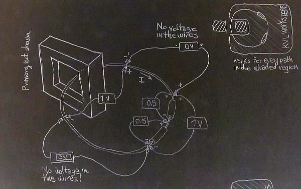
Why does the wall have to be there? How about I put my wall here, in the very center of the toroid just to keep idiots from dropping their volt meter leads through there, as shown in the diagram below - it's functionally identical to your wall, yes? And its a lot less bricks!
https://i.postimg.cc/qqG0vgRV/20211124-213839.jpg
Above: See the crosshatched wall inside of the core.
Good, it seems that the top right corner of this image I posted nearly a week ago
has finally reached your brain. A little slow, but better late than never.
Sadly, my understanding hasn't changed. It's just taken you this long to get a clue about what I'm trying to say.
Of course, you still don't understand it even though I remade both images using the very same circuit. Voltage is path-dependent in both situations: with or without a wall.
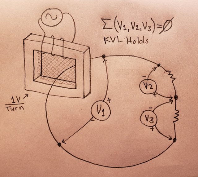
What we choose to do in order to be able to apply KVL in our circuit is limit our circuit path to the region of space where voltage between any two points is the same for all paths within that region of space. In short, we PRETEND voltage is single-valued because we willingly ignore the paths along which it will give multiple values.
So to clarify, if I put up a wall inside my core as seen in my diagram directly below, and this wall keeps all the idiots from dropping their volt meters in the hole, then the secondary winding measures and models as exactly a single turn secondary, right? And as long as no other elements of my loop breach that wall, then I'm golden, right?
https://i.postimg.cc/qqG0vgRV/20211124-213839.jpgAnd since your own trusted source says that KVL holds as long as the current_in = current_out and the voltage is unambiguously physically measurable, I guess we have to agree, with my boundary wall KVL then holds for the exact same reason I've been droning on about for a year now - because you have to model reality or your math isn't going to match reality. The wall just keeps the idiots from dropping their volt meters through the forbidden stargate hahahaha

(And NO NO NO, I'm not saying it IS a stargate, I'm saying it MODELS AND MEASURES AS IF it is.)
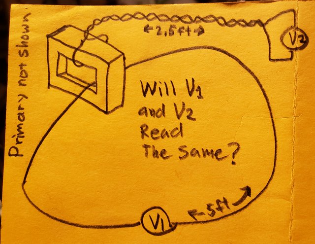
You already agreed that KVL would hold for "V2" in the below diagram, and you also already agreed that "V1" and "V2" would unambiguously read the same with a physical measurement:
 https://i.postimg.cc/fTgyDNp0/20211119-030105.jpg
So I really don't know why you can't agree that the 2 terminal output of a toroidal transformer can work fine as an element in a KVL loop.
The bag of nails in my basement is nodding. It seems to be able to understand this.
Do you?
This box of left-handed six-faced lug nuts in my basement is shaking its head at you. It cannot believe you've had this explained so clearly to you and you still don't get it!
Does it help you when I talk about the box of lug nuts in my basement?
Actually, your ring above is COMPLETELY lumpable as a 1 turn transformer output in series with two resistors.
Prove it.
Yipes you're insufferable when it comes to quoting out of context!
You quote me saying "your ring above..." and you put a different picture there. It's similar, but dude, put out an effort to quote in context! All you got to do is include the picture I'm talking about in the quoted text so we can all see what I'm really referring to!
I'll put it here for you:
 https://i.postimg.cc/5NyZDPVS/Unlumpable-circuit.jpg
Now, as you were saying:
Actually, your ring above is COMPLETELY lumpable as a 1 turn transformer output in series with two resistors.
Prove it.
Prove what?
You already agreed that "V1" and "V2" read the same in the following diagram - and you also already agreed that "V2" is suitable for use in a KVL loop.
Furthermore, your trusted sources say that if Iout=Iin and the voltage across the terminals is unambiguously physically measurable, then KVL holds.
And because you already agreed that V1 and V2 in diagram below read the same, that tells me they read UNAMBIGUOUSLY so how can you not agree that KVL would hold in V1 as well?
https://i.postimg.cc/fTgyDNp0/20211119-030105.jpgDraw the resistors in that exact position around the shaded dB/dt region, with that shape and size (the one where I write "Example where there is no room to twist it"), and then draw a green dashed line that is your circuit's path. It has to join the resistors' terminals with one another and with the lumped transformer. Note that the shaded disk should all be contained into your lumped transformer, and your green dashed circuit path must NOT INCLUDE the shaded disk.
Go ahead, I'll wait for your picture.
What're you blathering on about?
You've already agreed that V1 and V2 will read the same in the above yellow diagram, and you've also agreed that V2 is suitable to be an element in a KVL loop.
AAAAaaand you've also agreed that KVL will hold if we put an imaginary brick wall inside the core that prevents all idiot volt meters from falling through the hole as shown in the diagram directly below:
You full well know that if I measure the voltage across that inner section of winding it will read 1 turn of voltage. Of course the voltage isn't actually all induced just inside there, but because the rest of our loop is not inside there, IT MODELS AND MEASURES AS IF IT IS ENTIRELY INDUCED INSIDE THE CORE and as such ONE TURN MODELS AND MEASURES AS EXACTLY A SINGLE TURN, which is what my claim is.
Are you actually denying that the voltage measured by V1 in diagram below will be something other than one turns worth of voltage?
https://i.postimg.cc/qqG0vgRV/20211124-213839.jpg
Just like shown with my Lewin Clock, there are planes along which probe leads may be run where there is no non-conservative field which allows unambiguous physical measurements to be made of the two half-turns.
I am not even sure this sentence makes any sense. But I will post the fields for your clock, and you will see that what you are measuring is the path integral of the conservative part of the electric field along the hands of the clock. So much for your good probing...
But let's put this aside for a while, you will comment when I have posted the pictures.
Huh? What the tarzan are you talking about?
For the moment, let's see that picture where you lump Lewin's rings by enclosing the shaded disk inside your transformer but NOT inside the circuit path that connects it to the resistors.
Remember, the resistor and the disk must remain in the same position, you cannot move them nor split it.
I am waiting.
What exactly are you asking?
You're not very good at describing it. Maybe you should draw something if you want something drawd
Ultimately, I'm not sure what your point is. You've already agreed with enough things it's time you step back and re-assess your angle of attack.
And the way you refuse to answer questions tells me you know you're wrong and you're just not about to admit it.
Why not just admit that a secondary winding on a toroidal transformer can be unambiguously measured and therefore KVL will hold fine with such an element?
Then we can move onto where the real dragons be, like aircore transformers and partial turns and all sorts of wonderful stuff!
The fact that you repeatedly refuse to answer that question tells me you don't know what you're talking about.
You're going off a script, hoping it makes more sense to me than to you. Dude, the reason your script looks like it stinks to you is because it stinks!


