-
Lumpable (lumped and not lumped) and unlumpable for Dummies
What makes a circuit lumpable? First of all its physical dimension have to be negligible compared to the wavelength of the electrical oscillations, and then voltages and currents 'offered' at the terminals must be well defined at any time. You want your circuit to be independent on how you measure voltage between two points or current along the same branch.
Here is a snapshot from page 2 of "Basic Circuit Theory", by Desoer and Kuh (don't let the title deceive you: this is the Bentley of circuit theory books).
Source: Desoer, Kuh "Basic Circuit Theory"
https://i.postimg.cc/sf4j3HbF/Desoer-Kuh.jpg
Most excellent! The Bentley of circuit theory books is very clear:
As long as the current entering one terminal equals the current exiting the other terminal and the voltage difference between the two terminals can be UNAMBIGUOUSLY defined by PHYSICAL measurements, then KVL holds!
That's what I've been saying!
So I guess then that both V1 and V2 in the below diagram would hold for KVL since you already admitted V2 will hold for KVL and that both V1 and V2 will measure the same with my volt meter, that's an unambiguous physical measurement, right?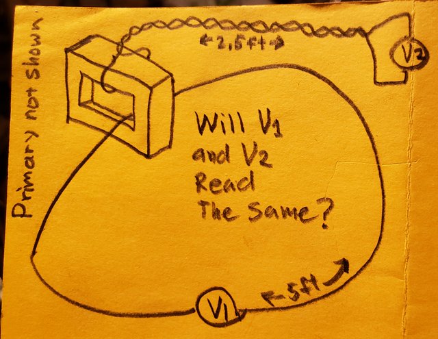
https://i.postimg.cc/fTgyDNp0/20211119-030105.jpgQuote
Note: in the case of Lewin's ring we know that the frequency is so low that retardation effects play no role; the condition that voltages and current be well defined is what we must be careful about. In particular, it's voltage the variable in discussion.
If we can interact with the component only through its terminals and we are not allowed to get inside, the only paths along which we can evaluate voltage (which is a path integral) are those 'outside' the component. And we require that the voltage be the same no matter how we choose the path joining the terminals.
In the case of magnetic components, we know that voltage along the path joining two points depends on the path, when we can go from one side of the magnetic flux region to the other. This is a direct consequence of one of Maxwell's equations (Faraday's law: curl E = -dB/dt) and basic vector integral calculus (Stokes theorem, the definitions of circulation and the definition of flux).
In order for voltage to be well defined, we must avoid paths that go through or 'on the other side' of the variable magnetic flux. The reason is simple: if the same starting and ending points admit two paths that are on opposite sides of the magnetic region, then the closed path formed by joining these two paths will enclose a variable flux and they must necessarily sum up to a nonzero value
Fig. two paths and the area enclosed (to be added later)
Now we know how to make voltage unique: allow only paths that cannot get into the forbidden zone. We enclose the component inside a black box (or an impenetrable wall) and we do not question what is inside. We must also ensure that our circuit path - the orange dashed line - does not contain variable magnetic flux itself.
Here is a lumpable circuit. The same circuit can be considered- lumpED, when we avoid the forbidden paths by erecting an impenetrable wall and we only access the magnetic component through its terminals (note the circuit path that does not go into the forbidden zone, but instead jumps at the terminals). KVL works inside the green circuit path.
- NOT lumped, when we consider a circuit path (for the same physical system that we usually address with the name 'circuit') that encloses part or all of the variable magnetic flux region. In this case any path inside the orange dashed line that represent the circuit's premises is allowed. Some of these paths - not all, but only one would suffice - can 'go on the other side' of the magnetic region, making voltage between two points NOT WELL DEFINED.

Fig. the same lumpable circuit can be considered either lumped or not lumped
https://i.postimg.cc/8kFQxNqc/Lumpable-can-be-lumped-or-not.jpg
Why does the wall have to be there? How about I put my wall here, in the very center of the toroid just to keep idiots from dropping their volt meter leads through there, as shown in the diagram below - it's functionally identical to your wall, yes? And its a lot less bricks!
https://i.postimg.cc/qqG0vgRV/20211124-213839.jpg
Above: See the crosshatched wall inside of the core.
The real answer is "Don't add undocumented turns to your transformer and expect physics to work."Quote
So far, so good: it looks like we have freedom to choose when we can make KVL works.
NO. There are circuits that are not lumpABLE. There are circuits where the circuit path is REQUIRED by definition or physical constraint to include the variable flux region. In this case it is not possible to find a green circuit path that connects the lumped components AND does not contain the variable flux region at its interior. Only orange paths are available.
Lewin's ring is an example of such a circuit. The resistors R1 and R2 are required to be on the opposite sides of the solenoid, i.e. the variable flux region. And you cannot find a circuit path that connects them without enclosing such forbidden zone. Voltages for points on your circuit will be path dependent.
Fig. an unlumpable circuit: you cannot exclude dB/dt region from the circuit path
https://i.postimg.cc/5NyZDPVS/Unlumpable-circuit.jpg
Actually, your ring above is COMPLETELY lumpable as a 1 turn transformer output in series with two resistors.
Theres NO REASON WHAT SOEVER that you cannot lump the transformer secondary as a one turn winding. The volt meter will give you an unambiguous physical measurement of that voltage, as you already admitted regarding my above yellow V1 and V2 diagram.Quote
And, no. You cannot model it with several tiny little transformer secondaries distributed along the perimeter, because you would forfeit the constraint that the two resistors be on the opposite sides of the variable magnetic region. It's exactly that constrain - your circuit path containing the dB/dt region - that makes Lewin's ring so special.
If you change the magnetic field region you are considering a different problem
There's nothing special about Lewin's ring. It's still two half-turns and two resistors all in series.
Just like shown with my Lewin Clock, there are planes along which probe leads may be run where there is no non-conservative field which allows unambiguous physical measurements to be made of the two half-turns.
I know Lewin pretended his bright red solenoid was infinitely long - that is a mistake many men make but it's never true - but even if his solenoid was infinitely long, a volt meter lead could still be run through the center of the solenoid along that plane which is free of non-conservative fields, and thus the voltage on a half-turn could still be unambiguously physically measured.
And the same thing is true for a toroid, if you drill a small hole through the center of the cross-section you can again run a wire along a plane of no non-conservative fields, so even with a toroid, the voltage across a half-turn can still be physically unambiguously measured.Quote
Fig. an unlumpable circuit: you cannot exclude dB/dt region from the circuit path
https://i.postimg.cc/x1KgZHcP/Spot-the-differences.png
In order to model it with two or four lumped coils, the magnetic field region must be split to accommodate a circuit path that does not include any of it. I used the same 'stellated' path style used by Feynman in figure 22-9 on page 22-7 of his second volume of lectures.
I'm beginning to think that your whole premise depends on the idea that you consider some core typologies to be impossible to probe half turns on, and I think you're entire argument is if it can't be probed, then KVL fails by definition, even though the voltages are all summing to zero as KVL states, it's just that you think you can't measure it.
But lets say for the sake of discussion that we have a transformer where we cannot actually physically unambiguously measure the voltage across the half-turns, we can still add up the voltage across the resistors and use KVL to solve for induced EMF -- AND WE WOULD BE RIGHT -- so did KVL really fail?
Can we all agree yet that integer turn secondaries on toroidal transformers are suitable as elements in KVL loops so long as we keep the bloody volt meters out of the core?
I don't see how you can disagree.
You already admitted that V1 and V2 will physically unambiguously read the same in my above yellow diagram, and you also admitted that V2 (the twisted pair instance) would hold as an element in a KVL loop.
And your very opening source says that KVL holds as long as the input and output current are the same and the voltage across the terminals is unambiguously physically measurable.
How can you deny it? -
You have nothing else but to resort to the "Moral High Ground Fallacy". On the other hand, the KVL side has provided theoretical results and experimental results that perfectly agree with each other. What have you provide? Just a big pile of steaming BS.
If both your theory and experiments depend on each other, that'll do you no good.
Because the experimental data presented here was obtained by more or less blindly poking around circuits with a volt meter, and without any understanding of what is actually going on. So the measurements taken do not support in any form the claim that "KVL holds".
Talk for yourself! Don't reflect your ignorance into other people. When I saw Lewin's experiment for the first time I thought immediately: he is ignoring the induced voltage in the scope probes! The other day I showed Lewin's circuit to a friend of mine and almost instantaneously he also said "he is measuring the voltages incorrectly". I bet that is the case with the vast majority of people that know how to use an oscilloscope.
As for "If both your theory and experiments depend on each other, that'll do you no good", well, last time I checked that is how science works. That is exactly how Maxwell equations were derived.
That's an engineers knee-jerk reflex, I know. That's how we're trained and conditioned by test equipment salesmen. I thought so as well, it must be some error in probing. It's not possible to measure two different voltages in the same spot. There must be an identifiable "transformer" in there. The "wires" must have a voltage across. That was until I understood some critical bits of Faradays Law and Maxwells equation concerning it. I watched some MIT video, asked a friend of mine who is really knowledgeable about this stuff (not a physicist but an electrical engineer) and made my conclusions. This new understanding immediately explained the results Mehdi was getting and some other peoples experiments as well.
About the "experiments". It should be abundantly clear by now what is wrong with Jesses EI-core measurements and why they are no proof for "KVL holds". What more than "the solution is in the fields" (plural) can I say. One cannot consider only the magnetic flux and simply ignore the electric field that is inevitably present as well. -
It's not possible to measure two different voltages in the same spot.
But you aren't measuring the voltages in the same spot, are you? The two voltmeters are in two different spots. -
Why does the wall have to be there? How about I put my wall here, in the very center of the toroid just to keep idiots from dropping their volt meter leads through there, as shown in the diagram below - it's functionally identical to your wall, yes? And its a lot less bricks!
https://i.postimg.cc/qqG0vgRV/20211124-213839.jpg
Above: See the crosshatched wall inside of the core.
Good, it seems that the top right corner of this image I posted nearly a week ago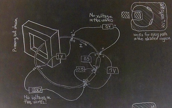
has finally reached your brain. A little slow, but better late than never.
Of course, you still don't understand it even though I remade both images using the very same circuit. Voltage is path-dependent in both situations: with or without a wall.
What we choose to do in order to be able to apply KVL in our circuit is limit our circuit path to the region of space where voltage between any two points is the same for all paths within that region of space. In short, we PRETEND voltage is single-valued because we willingly ignore the paths along which it will give multiple values.
The bag of nails in my basement is nodding. It seems to be able to understand this.
Do you?QuoteActually, your ring above is COMPLETELY lumpable as a 1 turn transformer output in series with two resistors.
Prove it.
Draw the resistors in that exact position around the shaded dB/dt region, with that shape and size (the one where I write "Example where there is no room to twist it"), and then draw a green dashed line that is your circuit's path. It has to join the resistors' terminals with one another and with the lumped transformer. Note that the shaded disk should all be contained into your lumped transformer, and your green dashed circuit path must NOT INCLUDE the shaded disk.
Go ahead, I'll wait for your picture.Quote
I am not even sure this sentence makes any sense. But I will post the fields for your clock, and you will see that what you are measuring is the path integral of the conservative part of the electric field along the hands of the clock. So much for your good probing...
Just like shown with my Lewin Clock, there are planes along which probe leads may be run where there is no non-conservative field which allows unambiguous physical measurements to be made of the two half-turns.
But let's put this aside for a while, you will comment when I have posted the pictures.
For the moment, let's see that picture where you lump Lewin's rings by enclosing the shaded disk inside your transformer but NOT inside the circuit path that connects it to the resistors.
Remember, the resistor and the disk must remain in the same position, you cannot move them nor split it.
I am waiting.
-
No, it all boils down to certain people being unable to understand what they read, and being incapable of assimilating new concepts that go beyond their limited knowledge. Like trying to explain the orbit of planets with epicycloids: it works numerically, but it betrays a fundamental ignorance of the actual physical phenomena behind the motion.
Do you really think that by now these guys haven't already figured out that their rhetoric is pointless? They know darn well that Lewin is right, Mehdi is wrong, KVL doesn't hold under a varying magnetic field, static wires are just low ohm resistors that can't generate voltages, you can measure two different voltages across the same two points in a circuit, etc., etc., etc.
So, if they are not intellectually impaired, why do they keep producing assertions that deny the evidence and reject facts and logic? Even when repeatedly debunked left and right?
As I said in an early post, stupidity is a moral issue. Even when you give them the answer they expect, they'll say you're wrong. This is because they determined arbitrarily that you're wrong. No matter what.
Although discussing with them may sometimes produce an interesting socratic-like dialog, it also may give the occasional reader the impression that their questioning is legitimate.
You have nothing else but to resort to the "Moral High Ground Fallacy". On the other hand, the KVL side has provided theoretical results and experimental results that perfectly agree with each other. What have you provide? Just a big pile of steaming BS.
It really is their religion, isn't it? I hate to say it, but that seems to be what it comes down to.
Yet the only thing you managed to prove is that Lewin is right and you are wrong. Keep on trying. Who knows you manage to win converts to the cause of stubborn ignorance. -
Not by my calculations!No, it all boils down to certain people being unable to understand what they read, and being incapable of assimilating new concepts that go beyond their limited knowledge. Like trying to explain the orbit of planets with epicycloids: it works numerically, but it betrays a fundamental ignorance of the actual physical phenomena behind the motion.
Do you really think that by now these guys haven't already figured out that their rhetoric is pointless? They know darn well that Lewin is right, Mehdi is wrong, KVL doesn't hold under a varying magnetic field, static wires are just low ohm resistors that can't generate voltages, you can measure two different voltages across the same two points in a circuit, etc., etc., etc.
So, if they are not intellectually impaired, why do they keep producing assertions that deny the evidence and reject facts and logic? Even when repeatedly debunked left and right?
As I said in an early post, stupidity is a moral issue. Even when you give them the answer they expect, they'll say you're wrong. This is because they determined arbitrarily that you're wrong. No matter what.
Although discussing with them may sometimes produce an interesting socratic-like dialog, it also may give the occasional reader the impression that their questioning is legitimate.
You have nothing else but to resort to the "Moral High Ground Fallacy". On the other hand, the KVL side has provided theoretical results and experimental results that perfectly agree with each other. What have you provide? Just a big pile of steaming BS.
It really is their religion, isn't it? I hate to say it, but that seems to be what it comes down to.
Yet the only thing you managed to prove is that Lewin is right and you are wrong.QuoteKeep on trying.
Thank you!QuoteWho knows you manage to win converts to the cause of stubborn ignorance.
You realize of course both sides feel the same way about the other side, right?
And besides, if your technique works for you, it should work for me, right? HEHE
But seriously, why not address the topic? Why not at the very least will you agree that a TWO TERMINAL transformer secondary on a toroidal transformer works fine as an element in a KVL loop?
PS: Happy Thanksgiving if you're in USA.
-
Why does the wall have to be there? How about I put my wall here, in the very center of the toroid just to keep idiots from dropping their volt meter leads through there, as shown in the diagram below - it's functionally identical to your wall, yes? And its a lot less bricks!
https://i.postimg.cc/qqG0vgRV/20211124-213839.jpg
Above: See the crosshatched wall inside of the core.
Good, it seems that the top right corner of this image I posted nearly a week ago
has finally reached your brain. A little slow, but better late than never.
Sadly, my understanding hasn't changed. It's just taken you this long to get a clue about what I'm trying to say.QuoteOf course, you still don't understand it even though I remade both images using the very same circuit. Voltage is path-dependent in both situations: with or without a wall.
What we choose to do in order to be able to apply KVL in our circuit is limit our circuit path to the region of space where voltage between any two points is the same for all paths within that region of space. In short, we PRETEND voltage is single-valued because we willingly ignore the paths along which it will give multiple values.
So to clarify, if I put up a wall inside my core as seen in my diagram directly below, and this wall keeps all the idiots from dropping their volt meters in the hole, then the secondary winding measures and models as exactly a single turn secondary, right? And as long as no other elements of my loop breach that wall, then I'm golden, right?
https://i.postimg.cc/qqG0vgRV/20211124-213839.jpg
And since your own trusted source says that KVL holds as long as the current_in = current_out and the voltage is unambiguously physically measurable, I guess we have to agree, with my boundary wall KVL then holds for the exact same reason I've been droning on about for a year now - because you have to model reality or your math isn't going to match reality. The wall just keeps the idiots from dropping their volt meters through the forbidden stargate hahahaha
(And NO NO NO, I'm not saying it IS a stargate, I'm saying it MODELS AND MEASURES AS IF it is.)
You already agreed that KVL would hold for "V2" in the below diagram, and you also already agreed that "V1" and "V2" would unambiguously read the same with a physical measurement:
https://i.postimg.cc/fTgyDNp0/20211119-030105.jpg
So I really don't know why you can't agree that the 2 terminal output of a toroidal transformer can work fine as an element in a KVL loop.QuoteThe bag of nails in my basement is nodding. It seems to be able to understand this.
Do you?
This box of left-handed six-faced lug nuts in my basement is shaking its head at you. It cannot believe you've had this explained so clearly to you and you still don't get it!
Does it help you when I talk about the box of lug nuts in my basement?QuoteQuoteActually, your ring above is COMPLETELY lumpable as a 1 turn transformer output in series with two resistors.
Prove it.
Yipes you're insufferable when it comes to quoting out of context!
You quote me saying "your ring above..." and you put a different picture there. It's similar, but dude, put out an effort to quote in context! All you got to do is include the picture I'm talking about in the quoted text so we can all see what I'm really referring to!
I'll put it here for you:
https://i.postimg.cc/5NyZDPVS/Unlumpable-circuit.jpg
Now, as you were saying:QuoteQuoteActually, your ring above is COMPLETELY lumpable as a 1 turn transformer output in series with two resistors.
Prove it.
Prove what?
You already agreed that "V1" and "V2" read the same in the following diagram - and you also already agreed that "V2" is suitable for use in a KVL loop.
Furthermore, your trusted sources say that if Iout=Iin and the voltage across the terminals is unambiguously physically measurable, then KVL holds.
And because you already agreed that V1 and V2 in diagram below read the same, that tells me they read UNAMBIGUOUSLY so how can you not agree that KVL would hold in V1 as well?
https://i.postimg.cc/fTgyDNp0/20211119-030105.jpgQuoteDraw the resistors in that exact position around the shaded dB/dt region, with that shape and size (the one where I write "Example where there is no room to twist it"), and then draw a green dashed line that is your circuit's path. It has to join the resistors' terminals with one another and with the lumped transformer. Note that the shaded disk should all be contained into your lumped transformer, and your green dashed circuit path must NOT INCLUDE the shaded disk.
Go ahead, I'll wait for your picture.
What're you blathering on about?
You've already agreed that V1 and V2 will read the same in the above yellow diagram, and you've also agreed that V2 is suitable to be an element in a KVL loop.
AAAAaaand you've also agreed that KVL will hold if we put an imaginary brick wall inside the core that prevents all idiot volt meters from falling through the hole as shown in the diagram directly below:
You full well know that if I measure the voltage across that inner section of winding it will read 1 turn of voltage. Of course the voltage isn't actually all induced just inside there, but because the rest of our loop is not inside there, IT MODELS AND MEASURES AS IF IT IS ENTIRELY INDUCED INSIDE THE CORE and as such ONE TURN MODELS AND MEASURES AS EXACTLY A SINGLE TURN, which is what my claim is.
Are you actually denying that the voltage measured by V1 in diagram below will be something other than one turns worth of voltage?
https://i.postimg.cc/qqG0vgRV/20211124-213839.jpgQuoteQuote
I am not even sure this sentence makes any sense. But I will post the fields for your clock, and you will see that what you are measuring is the path integral of the conservative part of the electric field along the hands of the clock. So much for your good probing...
Just like shown with my Lewin Clock, there are planes along which probe leads may be run where there is no non-conservative field which allows unambiguous physical measurements to be made of the two half-turns.
But let's put this aside for a while, you will comment when I have posted the pictures.
Huh? What the tarzan are you talking about?QuoteFor the moment, let's see that picture where you lump Lewin's rings by enclosing the shaded disk inside your transformer but NOT inside the circuit path that connects it to the resistors.
Remember, the resistor and the disk must remain in the same position, you cannot move them nor split it.
I am waiting.
What exactly are you asking?
You're not very good at describing it. Maybe you should draw something if you want something drawd
Ultimately, I'm not sure what your point is. You've already agreed with enough things it's time you step back and re-assess your angle of attack.
And the way you refuse to answer questions tells me you know you're wrong and you're just not about to admit it.
Why not just admit that a secondary winding on a toroidal transformer can be unambiguously measured and therefore KVL will hold fine with such an element?
Then we can move onto where the real dragons be, like aircore transformers and partial turns and all sorts of wonderful stuff!
The fact that you repeatedly refuse to answer that question tells me you don't know what you're talking about.
You're going off a script, hoping it makes more sense to me than to you. Dude, the reason your script looks like it stinks to you is because it stinks! -
About the "experiments". It should be abundantly clear by now what is wrong with Jesses EI-core measurements and why they are no proof for "KVL holds". What more than "the solution is in the fields" (plural) can I say.
What do you think of Snedri's trusted source:
Isn't it pretty clear that if the voltage across the terminals can be unambiguously physically measured that KVL will hold?
(Please read the whole page, not just what he highlighted.)
Snedri already admitted that V1 and V2 in the following diagram will physically measure the same voltage, and that V2 will hold as an element in a KVL loop:
He also admitted that if we put up an imaginary wall to keep other stuff from going through the core, then the winding becomes suitable for being an element in a KVL loop:
Do you really think that the voltage reading is ambiguous on my EI-Core loop so long as I don't add or remove secondary turns without documenting them?QuoteOne cannot consider only the magnetic flux and simply ignore the electric field that is inevitably present as well.
You keep mentioning that but you won't explain more.
What does this electric field permeate? What if the transformer is inside a Faraday Shield?
Or what if it is enclosed in a superconducting Faraday Shield?
Does this magic field extend deep into the briny ocean? Deep into the earth?
Is it conservative or non-conservative?
Can it be measured without passing a wire through the hole in the core?
Just how well shielded would a transformer need to be before you would expect it to play nicely as an element in a KVL loop?
I really don't see how you can think that there is a non-conservative field for other elements that do not pass through the toroid or EI-Core.
Seriously man, you're smart enough to get this. The others aren't. That's probably why they carry on as if they could never be wrong, but you realize that your position is difficult to support. And now you're on to talking about an "inevitable electric field." I would much rather you tell me about a measurable E-Field, rather than one that you believe deep in your heart must be there for things to work the way you think.
Yeah I watched some MIT youtube videos too. I talked to people too. Does that make me right?
What makes an understanding right is when it accurately predicts and models reality.
And my EI-Core transformer test showed that both half-turns measured exactly as KVL predicts. -
[...]
Sorry man, it's all been explained and shown in pictures and equations. But you just ignore them. Instead you make up incomplete analogies, like the "wall inside the transformer". Go back and look at the diagram I made about the ring core transformer. It's all there in red, blue and green. If you don't understand how this transfers to your EI core, sorry, not going to spoonfeed you.
The electric field is there. It cannot be ignored. It cannot be discussed away if you don't want to neglect everything discovered in physics since 1861. -
It's not possible to measure two different voltages in the same spot.
But you aren't measuring the voltages in the same spot, are you? The two voltmeters are in two different spots.
Assuming we're talking about this:
Electrically it's the same spot. The piece of wire between the resistors has 0V across it, so obviously there's no potential. You could move the probe points of the volt meters (those across "R" and "2R") until they touch, they would still show the same value, provided the wires have negligible resistance.
PS: edited for clarity. -
Why does the wall have to be there? How about I put my wall here, in the very center of the toroid just to keep idiots from dropping their volt meter leads through there, as shown in the diagram below - it's functionally identical to your wall, yes? And its a lot less bricks!
https://i.postimg.cc/qqG0vgRV/20211124-213839.jpg
Above: See the crosshatched wall inside of the core.
The real answer is "Don't add undocumented turns to your transformer and expect physics to work."
This "wall inside the transformer" is not equivalent. It makes people believe they'll be safe if their probe leads do not cross it and so they stop looking at the complete paths and instead concentrate on "forbidden planes". It has certainly not stopped you from adding "undocumented turns" in your EI core experiment.
-
Your probing method inherently subtracts induced voltage from your reading, leaving you with only the ohmic losses.
[...]
You are, buy definition, only measuring ohmic losses, because you are using a method of measuring which specifically subtracts all induced voltage differences.
But there's no choice, really. Your voltmeter will only show you the sum of the electric fields along the path formed by its probe leads and whatever is between the tips. This path can either be conservative ("blue") or non-conservative ("red"). But you must treat each path as independent from all other paths. For example in my diagram, the RED path containing the rightmost voltmeter only sums up fields along its path, i.o.w the electric field across "2R" and all external electric field components around the core (green arrows) it encloses! It doesn't matter if the probe leads penetrate your "wall inside the transformer" because "2R" is also on that path, closing the loop. Do you still not see what happened with your EI core?QuoteNow the big question is of course, can KVL be somehow made to work in this arrangement, and for that we need to find an equivalent circuit with lumped elements. That will prove to be difficult, because one cannot find a place where to stick a lumped transformer winding or voltage source and still satisfy all the measurements taken in the various places. We can obviously not put it in the wires between the resistors, because we measure 0V across them. It can also not be in "R" and/or in "2R". If we put a 2/3V source "inside" 2R, that would violate the "-1/3V" reading on the rightmost volt meter.
So, where is it? Apparently it is there, but we cannot pinpoint it and measurements between two identical points show different results depending on how we instrument the circuit (1/3V, 2/3V, -1/3V). For circuit theory and KVL this is a nightmare. That's why there are "equivalent circuits" e.g. for transformers which try to model physics with lumped elements full of imaginary numbers and "magic items" like ideal transformers because they relieve engineers of having to think about physics. And to make KVL work. But now and then, when Sir James Clerk Maxwell makes an appearance, everyone is baffled why their circuits don't work.
The only reason we cannot pinpoint it is because it is all the way around. Sure, it MODELS and MEASURES as if it's at the center, but if you look at Faraday, and Maxwell, it's dB/dt inside an area, and measuring it on a solid core of effective infinite length is difficult because the active element of the transformer is no different than our volt meter leads, and they too, suffer from that same effect of induced voltage.
Now wait a second. "We cannot pinpoint it because it is all the way around" does not rhyme with treating the red wires in your EI core experiment as lumped voltage sources, right? Because there you claim (incorrectly) that, since your volt meter leads don't "go through the core" they don't have any voltage induced, right? So the only voltage source must be the red wire, right? So which way will you have it? It cannot be both.QuoteAnd then we end up with this crazyness where you claim there is 0 volts across all the wires, but 1 volt across the resistors, where exactly is the voltage coming from?
Oh? It's induced? So it is there. It's just difficult to measure in certain specific situations which have been designed for it to be difficult to measure.
So what you're saying is that Nature is treating poor engineers badly and making it difficult for them on purpose. Bad, bad Nature! I shall put you on my naughty list! No presents for you this Christmas!
SCNR
PS: the induced potential is not difficult to measure. Just sum up all electric fields along the "R+2R" loop and there you have it: 1V. Just be careful not to accidentally add another non-conservative external electric field to your measurements and forget to account for it.
-
[...]
Sorry man, it's all been explained and shown in pictures and equations. But you just ignore them.
And you're ignoring observable reality, and refusing to answer questions which would allow you to see how wrong you are, so what good are your so called "explanations?"
You used to be willing to put your beliefs about reality to the test. Now you're getting like the other more experienced lewinites who like to wax eloquent but refuse to actually answer questions because they know they'll fail reality checks.QuoteInstead you make up incomplete analogies, like the "wall inside the transformer".
Snedri came up with the virtual wall analogy. He had his outside the transformer as an infinite plane, but putting it inside like I did has the exact same effect on measurable reality.QuoteGo back and look at the diagram I made about the ring core transformer. It's all there in red, blue and green. If you don't understand how this transfers to your EI core, sorry, not going to spoonfeed you.
The thing is, I do understand how transformers model and measure. You don't. That's why you've made like 5 wrong predictions now, because you just don't understand observable reality when it comes to transformers. But hang in here, if you don't slip off into never-never land like the others, you'll get to where you understand it.QuoteThe electric field is there. It cannot be ignored. It cannot be discussed away if you don't want to neglect everything discovered in physics since 1861.
That sounds like an argument from personal conviction, no? That's incredibly weak.
You say "The electric field is there, extending to infinity." But you haven't told me how I can measure it.
Nor have you said whether it is blocked by Faraday shielding, or earth or water or whether there is any way to detect it.
How can I measure this electric field extending to infinity as you first described it?
Speaking of making things up... I think you made that one up.
You also keep refusing to answer whether the electric field from the following transformer also extends into infinity:
Seriously though, how can I measure this electric field extending into infinity from a toroidal transformer?
I can see if you had an infinitely long solenoid, then you could argue that you had both magnetic and electric fields extending to infinity since the solenoid itself extends to infinity.
But the beauty of a toroid is that it wraps up infinity to the area the size of a wallnut, or however big the toroid is.
As I said, seriously, what's the deal with this electric field around a toroid that extends to infinity? An unmeasurable unstoppable field?
You made it up, and that's like the 5th major misunderstanding you've demonstrated. -
Why does the wall have to be there? How about I put my wall here, in the very center of the toroid just to keep idiots from dropping their volt meter leads through there, as shown in the diagram below - it's functionally identical to your wall, yes? And its a lot less bricks!
https://i.postimg.cc/qqG0vgRV/20211124-213839.jpg
Above: See the crosshatched wall inside of the core.
The real answer is "Don't add undocumented turns to your transformer and expect physics to work."
This "wall inside the transformer" is not equivalent.
Please explain. Do you mean that assuming no probe wires breach the wall in the above diagram, there is still path dependence effecting the probes wires?
Are you saying somehow my volt meter can possibly read anything other than the unambiguous voltage of 1 turns worth of induced voltage, assuming my volt meter leads don't breach the wall?QuoteIt makes people believe they'll be safe if their probe leads do not cross it and so they stop looking at the complete paths and instead concentrate on "forbidden planes". It has certainly not stopped you from adding "undocumented turns" in your EI core experiment.
Whaddya mean? Each of my half turns were exactly a half turn. And all four voltages summed to zero.
Your pipe dream about this magic E-Field that extends to infinity has got you all confused. Please find a way to measure that or give up the idea. -
Your probing method inherently subtracts induced voltage from your reading, leaving you with only the ohmic losses.
[...]
You are, buy definition, only measuring ohmic losses, because you are using a method of measuring which specifically subtracts all induced voltage differences.
But there's no choice, really.Your voltmeter will only show you the sum of the electric fields along the path formed by its probe leads and whatever is between the tips.
As I said before, that's why we MODEL and MEASURE a toroidal transformer in an integer number of turns.
If we have an EI core, then we can use half-turns.QuoteThis path can either be conservative ("blue") or non-conservative ("red"). But you must treat each path as independent from all other paths. For example in my diagram, the RED path containing the rightmost voltmeter only sums up fields along its path, i.o.w the electric field across "2R" and all external electric field components around the core (green arrows) it encloses! It doesn't matter if the probe leads penetrate your "wall inside the transformer" because "2R" is also on that path, closing the loop. Do you still not see what happened with your EI core?
So far as you continue to shield yourself from reality, it's not going to make sense. I have asked you multiple times and I ask again: In the diagram directly below, will V1 and V2 read the same voltage? Will either V1 and/or V2 be suitable for use as an element in a KVL loop?
If you were to answer that truthfully, you'd have to say that yes they both read the same and yes a KVL loop would measure to be holding with either V1 or V2. (Heh, or both, as two different elements, which is what my EI-Core was.)
At the end of the day, how can you not see that KVL gives every appearance of holding in this case?Quote
Wrong.QuoteNow the big question is of course, can KVL be somehow made to work in this arrangement, and for that we need to find an equivalent circuit with lumped elements. That will prove to be difficult, because one cannot find a place where to stick a lumped transformer winding or voltage source and still satisfy all the measurements taken in the various places. We can obviously not put it in the wires between the resistors, because we measure 0V across them. It can also not be in "R" and/or in "2R". If we put a 2/3V source "inside" 2R, that would violate the "-1/3V" reading on the rightmost volt meter.
So, where is it? Apparently it is there, but we cannot pinpoint it and measurements between two identical points show different results depending on how we instrument the circuit (1/3V, 2/3V, -1/3V). For circuit theory and KVL this is a nightmare. That's why there are "equivalent circuits" e.g. for transformers which try to model physics with lumped elements full of imaginary numbers and "magic items" like ideal transformers because they relieve engineers of having to think about physics. And to make KVL work. But now and then, when Sir James Clerk Maxwell makes an appearance, everyone is baffled why their circuits don't work.
The only reason we cannot pinpoint it is because it is all the way around. Sure, it MODELS and MEASURES as if it's at the center, but if you look at Faraday, and Maxwell, it's dB/dt inside an area, and measuring it on a solid core of effective infinite length is difficult because the active element of the transformer is no different than our volt meter leads, and they too, suffer from that same effect of induced voltage.
Now wait a second. "We cannot pinpoint it because it is all the way around" does not rhyme with treating the red wires in your EI core experiment as lumped voltage sources, right?
I know this is hard for you to understand, but bear with me.
It is completely possible for the induced voltage to be induced all the way around while modeling it for the sake of KVL as a lumped voltage source BECAUSE none of the rest of the mesh passes through the core, and thus none of the rest of the mesh resides in any non-conservative field, because all paths that do not cross through the core are path-independent.QuoteBecause there you claim (incorrectly) that, since your volt meter leads don't "go through the core" they don't have any voltage induced, right?
NOOOOO! I am claiming that they MODEL AND MEASURE as if they have no voltage induced when they don't go through the core. There is no non-conservative field OUTSIDE an (ideal) toroidal transformer core.QuoteSo the only voltage source must be the red wire, right? So which way will you have it? It cannot be both.
How can you not see that I'm talking about HOW IT MODELS AND MEASURES?
KVL works on how it models and measures.QuoteQuoteAnd then we end up with this crazyness where you claim there is 0 volts across all the wires, but 1 volt across the resistors, where exactly is the voltage coming from?
Oh? It's induced? So it is there. It's just difficult to measure in certain specific situations which have been designed for it to be difficult to measure.
So what you're saying is that Nature is treating poor engineers badly and making it difficult for them on purpose. Bad, bad Nature! I shall put you on my naughty list! No presents for you this Christmas!
SCNR
ha ha very good!
But in all seriousness, I have clearly demonstrated that when we run our volt meter leads along planes where there are no fields, we can in fact measure induced voltages on even many topologies of air-core and open ended transformers.QuotePS: the induced potential is not difficult to measure. Just sum up all electric fields along the "R+2R" loop and there you have it: 1V. Just be careful not to accidentally add another non-conservative external electric field to your measurements and forget to account for it.
So can we just add up the ohmic losses, calculate the induced voltage, and sum that all up and find it to be zero, and then deduce that KVL holds, even for Lewin's loop?
After all, if he had summed up his ohmic losses he could have then flipped the sign and calculated the induced voltage, and if he had them added that all up, it would have summed to exactly zero! ha ha ha
-
Sadly, my understanding hasn't changed.
...
...
...
Dude, the reason your script looks like it stinks to you is because it stinks!
Oh, goodness me. What a wondrous, copious and melliflously superfluous word salad. All to hide the fact that you cannot lump Lewin's ring. Here, let me repeat the question you are so eloquently avoiding to answer.
This is Lewin's ring: two resistors in a single loop that goes around a circular region (let's consider it of the same size as the loop, so you can see there is no 'room to twist' the wires) of variable magnetic field. The resistors are required to be on the opposite sides of the variable magnetic field region.
https://i.postimg.cc/pLmfyHxZ/Lewin-ring-is-unlumpable.jpg
Please, show everybody you can draw a circuit path (make it green, meaning it's 'flux-free') that joins the resistors' terminals to the "lumped transformer secondary" terminals and DOES NOT INCLUDE the variable magnetic field region in its interior. Like I did for the lumpABLE circuit I decided to see as lumpED (in my post "Lumpable (lumped and not lumped) and not lumpable circuits for dummies").
In addition, you can also show everybody you can draw the path inside your "lumped transformer secondary" that DOES INCLUDE the variable magnetic field region (make it orange) but IS NOT part of the green circuit path.
I will show you that if you can do that you will run into contradiction.
Too bad my armchair is at the quantum mechanic's shop for repairs and I cannot fly away to another galaxy. -
Oh boy, where to even begin...
Okay, first of all: I'm not in denial of observable reality. In fact, I took the reality YOU observed, turned it into a nice, colorful diagram and explained each measurement YOU did using only Ohm, Maxwell and Faraday. I showed in which loops voltage is induced and why not in others, explained every number you obtained.
Here it is again:
Second: I did not "dream up" any "magic electric field". It's existence was found and explained by James Maxwell. It's his second field equation.Quote from: WikipediaThe Maxwell–Faraday version of Faraday's law of induction describes how a time varying magnetic field creates ("induces") an electric field
Third: It is very obvious how to measure it: create a wire loop around any area with changing magnetic flux, create some discontinuity (make a cut, put a resistor in the loop), measure the electric field across it. The probe is just some wire coiled up. It senses non-conservative electric fields. Just the same, each turn around a transformer core "measures" this electric field.
I hope this is not too much to stomach.
You mentioned repeatedly how the magnetic flux is fully contained inside a transformers core (which is not exact but, eh, good enough). Then explain how a conductor (charge particles) outside of the core and thus outside of the magnetic flux, can interact with it. "Spooky action at a distance"? The answer "Dude, because Faraday" is not enough. What is the mechanism behind it?
Btw how's that lumped circuit coming along @Sredni asked you to come up with?
-
Oh, goodness me. What a wondrous, copious and melliflously superfluous word salad. All to hide the fact that you cannot lump Lewin's ring. Here, let me repeat the question you are so eloquently avoiding to answer.
Says the guy that when solving Lewin's ring, the first thing he does is to lump the EMF, and then he follows up by using KVL to find the voltages in the resistors! -
Sadly, my understanding hasn't changed.
...
...
...
Dude, the reason your script looks like it stinks to you is because it stinks!
Oh, goodness me. What a wondrous, copious and melliflously superfluous word salad. All to hide the fact that you cannot lump Lewin's ring. Here, let me repeat the question you are so eloquently avoiding to answer.
This is Lewin's ring: two resistors in a single loop that goes around a circular region (let's consider it of the same size as the loop, so you can see there is no 'room to twist' the wires) of variable magnetic field. The resistors are required to be on the opposite sides of the variable magnetic field region.
https://i.postimg.cc/pLmfyHxZ/Lewin-ring-is-unlumpable.jpg
Please, show everybody you can draw a circuit path (make it green, meaning it's 'flux-free') that joins the resistors' terminals to the "lumped transformer secondary" terminals and DOES NOT INCLUDE the variable magnetic field region in its interior. Like I did for the lumpABLE circuit I decided to see as lumpED (in my post "Lumpable (lumped and not lumped) and not lumpable circuits for dummies").
In addition, you can also show everybody you can draw the path inside your "lumped transformer secondary" that DOES INCLUDE the variable magnetic field region (make it orange) but IS NOT part of the green circuit path.
I will show you that if you can do that you will run into contradiction.
Too bad my armchair is at the quantum mechanic's shop for repairs and I cannot fly away to another galaxy.
That's not exactly Lewin's ring, the resistors are too big, but I think I understand what you're asking - and I'll draw a better representation of the Lewin Ring and respond to that after you answer some questions.
It seems you're way behind on answering questions -- all you do is ask ask ask ask, but you never answer in the last few days. It's about time you warmed up your crystal ball to get some answers!
Here's some questions I've been asking for days and you're refusing to answer:
You have admitted that in the V1 and V2 voltages in the diagram directly below will both read the same voltage, and you have also admitted that V2 will be suitable as an element in a KVL loop:
Question One:
How can V1 not also be suitable since they both measure the same voltage? Your own trusted source says that if an unambiguous physical measurement of the voltage across the two terminals can be obtained, then KVL holds! How can V1 not work for KVL?
https://i.postimg.cc/fTgyDNp0/20211119-030105.jpg
Question Two:
Considering your own trusted source, if a ONE TURN TRANSFORMER SECONDARY on a toroidal transformer has a voltage that is unambiguously physically measurable, then it should qualify as an element for a KVL loop, Correct?
For example, in the following transformer diagram with a safety wall in the center, why would the output winding not be suitable as an element in a KVL loop?
https://i.postimg.cc/qqG0vgRV/20211124-213839.jpg
If you think the above secondary winding is not suitable in an element in a KVL loop, then why? It is possible to unambiguously measure the voltage, right? So then according to the following textbook, which you yourself cite, KVL should hold, right?
https://i.postimg.cc/sf4j3HbF/Desoer-Kuh.jpg
If you honestly answer the above questions and I'll do my best to draw up Lewin's loop and show how I would measure the voltage across the half turns. -
Oh, goodness me. What a wondrous, copious and melliflously superfluous word salad. All to hide the fact that you cannot lump Lewin's ring. Here, let me repeat the question you are so eloquently avoiding to answer.
Says the guy that when solving Lewin's ring, the first thing he does is to lump the EMF, and then he follows up by using KVL to find the voltages in the resistors!
No, says the guy who uses Faraday's law and not KVL, but you can't tell the difference.
Ok, this had to be just an appendix to my post "What about the other forms of EMF? Uh, what about 'em(f)?", but since you are impatient, I will anticipate it.
Lewin's ring with a localized EMF: adding a battery
The following example shows that the localized EMFs are part of the path integral on the left of Faraday's equation (in its integral form), while the delocalized inductive EMF is the surface integral on the right. By not being part of the PATH integral, the delocalized inductive EMF is at all effects invisible in the closed circuit represented by the ring.
So, let's solve for the voltages and current in a Lewin ring with the addition of the localized EMF from a battery (shown in the following drawing as a 9V battery)
page 1 https://i.postimg.cc/D0mW70jF/screenshot-4.png
Now, pay attention at how the full closed path is partitioned, because it's that exhaustive partitioning that show established that "the inductive EMF is NOT on the path". Or, as Kirchhoff would have said it: "die induktive elektromotorische Krafte ist NICHT auf dem Wege".
page 2 https://i.postimg.cc/zBGvk31W/screenshot-5.png
Oh, look. I have started with Faraday's law, in its local, differential form. Used Stokes theorem to obtain the integral form of Faraday's law, then applied Faraday's law to obtain an equation that involves, the nonlocalized EMF that I call EMF(t), the localized EMF Vbatt(t) and the current I(t).
Then I solve this Faraday equation to find the current I(t).
No sign of KVL, at all. Because KVL is DEAD.
But the most interesting part is that the source of EMF that is not delocalised, the very localized and lumped EMF battery, shows up as a piece of the path integral on the left hand side. That is the nest where the localised EMF Kirchhoff was arguing about, are born. You know, the "electromotorischen Krafte" he writes about in his formulation.
(This will be more clear when I post the next message)
-
No, says the guy who uses Faraday's law and not KVL, but you can't tell the difference.Oh, goodness me. What a wondrous, copious and melliflously superfluous word salad. All to hide the fact that you cannot lump Lewin's ring. Here, let me repeat the question you are so eloquently avoiding to answer.
Says the guy that when solving Lewin's ring, the first thing he does is to lump the EMF, and then he follows up by using KVL to find the voltages in the resistors!
A rose by any other name is still a rose! You are the one that can not tell they are the same...
-
It seems you're way behind on answering questions -- all you do is ask ask ask ask, but you never answer in the last few days. It's about time you warmed up your crystal ball to get some answers!
Here's some questions I've been asking for days and you're refusing to answer:
No, I have answered the questions that made some sense. But you have such big holes in your knowledge that you end up asking questions that have little to no sense. I was going to make a post about the misconceptions your posts are full of, but there are way too many. For example, I have written many many times that KVL applies in all regions of space that do not contain/cut a variable magnetic flux. So, in the lumpable circuit with the twisted wire it goes without saying that, since there is no changing flux in the small loop formed by V2, the wires and the jump at the first twist, KVL works.
But you keep asking questions that contain nonsense in themQuoteYou have admitted that in the V1 and V2 voltages in the diagram directly below will both read the same voltage, and you have also admitted that V2 will be suitable as an element in a KVL loop:
What the heck does "V2 (or V1) is suitable as an element in a KVL loop" even mean???
V2 is a voltmeter, to begin with, but let's consider it a branch. A branch alone can be part of a loop to which KVL applies (works) and AT THE SAME TIME be part of a loop to which KVL does NOT apply.
Case in point: Lewin's ring with the two 'external' voltmeters. V1 forms a loop with R1 that you can apply KVL to, but forms with R2 (and V2) loop(s) to which you cannot apply KVL to, you need Faraday.
Therefore:QuoteQuestion One:
How can V1 not also be suitable since they both measure the same voltage? Your own trusted source says that if an unambiguous physical measurement of the voltage across the two terminals can be obtained, then KVL holds! How can V1 not work for KVL?
This question betrays your confusion. I cannot answer this question because you are showing not to possess the prerequisite to formulate a rational question. V2 in the twisted circuit can be though as part of a circuit that stops at the first twist. If you limit yourself to paths that are inside that little loop, V2 will always be part of loops to which KVL can be applied (because in the universe that is the area enclosed by your circuit path there is no dB/dt).
Yes, you can define your circuit path to follow all the twists and go around the core, but that betrays your ignorance of the purpose of making the transformer's terminal so close together: it's to treat the circuit with V2 as lumpED.
V1, on the other hand, is part of a circuit whose circuit path you can immediately see going around the core. Anyway, being a lumpABLE circuit you can choose both ways. If you choose the copper as the trail of your circuit path, you include the dB/dt region inside it. There are paths that when part of a loop along with V1 will go around the core, hence KVL will not apply. Faraday's will.QuoteQuestion Two:
Considering your own trusted source, if a ONE TURN TRANSFORMER SECONDARY on a toroidal transformer has a voltage that is unambiguously physically measurable, then it should qualify as an element for a KVL loop, Correct?
For example, in the following transformer diagram with a safety wall in the center, why would the output winding not be suitable as an element in a KVL loop?
Again, the question betrays your ignorance. That is a lumpABLE circuit. You can treat it either as NOT LUMPED, by allowing paths that go around the core by considering an orange circuit path that follows the conductor around the core, or lumpED by denying this possibility by considering a green circuit path that jumps at the terminals, excluding this possibility. The wall is just a way to represent the fact that you are denying this possibility and your circuit path skips the innards of the transformer. (EDIT: to clarify: what really counts is how you define your circuit path: is it the green path that does not include the dB/dt region? Or is it the orange path that includes the dB/dt region?)
If you deny this possibility, then your voltages will be well defined (as Desoer and Kuh require for KVL to hold).
If you allow this possibility, then your voltage can be multivalued (and Desoer Kuh will say that KVL ceases to work for those loops with a part 'going the other side').
(To tell it all, we should make the terminals close together so that the circuit itself can be shrinked to a point, but I decided not to push this. ) -
Oh boy, where to even begin...
Okay, first of all: I'm not in denial of observable reality. In fact, I took the reality YOU observed, turned it into a nice, colorful diagram and explained each measurement YOU did using only Ohm, Maxwell and Faraday. I showed in which loops voltage is induced and why not in others, explained every number you obtained.
Here it is again:
Excellent, so if you don't deny observable reality, then please tell me that you agree that the two terminals of a single turn transformer secondary on a toroidal core will MEASURE AND MODEL just fine as a lumped element in a KVL loop, like this:
If not, why do you think the V1,V2,V3 would not sum up to zero?QuoteSecond: I did not "dream up" any "magic electric field". It's existence was found and explained by James Maxwell. It's his second field equation.
Ahhh, you have to add in a secondary winding measure this electric field you talk about extending to infinity. Why'd I have to ask 3 times to get an answer?Quote from: WikipediaThe Maxwell–Faraday version of Faraday's law of induction describes how a time varying magnetic field creates ("induces") an electric field
Third: It is very obvious how to measure it: create a wire loop around any area with changing magnetic flux, create some discontinuity (make a cut, put a resistor in the loop), measure the electric field across it. The probe is just some wire coiled up. It senses non-conservative electric fields. Just the same, each turn around a transformer core "measures" this electric field.
You may extend your secondary transformer load wires off into infinity and say "Ahah! An E-Field at Infinity!" But I could sneak in and replace your toroidal transformer with a non-inductive DDS waveform generator and you'd still be out there at infinity gloating about your E-Field which you presumed was made by your toroidal transformer, because the signal from my DDS would be indistinguishable.
And when you do form a loop, you get v. Then you add another loop, and you get 2v. and so on. Is that like stacking 10 plates and being able to pile 10 times the food on the top plate before it spills over the sides?
Obviously it's the dB field that induces the E-Field, and obviously there's "no" dB field outside the toroid core, so where exactly is the E-Field induced? In a conductor enclosing the dB region.
But let's say you take a toroidal transformer, and you have it shielded in the thickest bestest Faraday and magnetic shielding known to mankind, and yet you have a tiny hole going through the shielding so that a wire can pass through the hole in the toroid and come out the other side. You still have a full turn's induced voltage even though only a fraction of the turn is actually inside the Faraday and magnetic shielding.
So what do you have, a super powerful field that blasts through the best known shielding known to mankind, which is completely undetectable unless you get INSIDE the shielding?
As others have said, nature does what nature does. We do our best to model it with physics, but physics are concepts and they don't always exactly describe the fullness of what nature is doing.
But anyway, so what does this have to do with KVL not holding when one of the elements is the secondary winding on a toroidal transformer?
Are you saying that the E-Field surrounding a toroidal transformer will cause unexpected readings if it is near a KVL loop?
If so, what do you expect? How would I observe this in real life?
When I measured EI-Core secondary widings in a loop, I found that KVL holds just fine.QuoteI hope this is not too much to stomach.
You mentioned repeatedly how the magnetic flux is fully contained inside a transformers core (which is not exact but, eh, good enough). Then explain how a conductor (charge particles) outside of the core and thus outside of the magnetic flux, can interact with it. "Spooky action at a distance"? The answer "Dude, because Faraday" is not enough. What is the mechanism behind it?
Nature.
We've figured out a number of different very clever ways to model nature in a number of different settings, but you tell me what the ACTUAL mechanism is behind it. What REALLY IS magnetism? You tell me.
At the end of the day, we can encase a toroidal transformer in the best shielding known to man, and it's output winding still has induced upon it a full turn's worth of voltage even though only a fraction of the turn is actually inside the shielding. So you argue that the remainder of the voltage is induced outside the shielding, even though there is no measurable magnetic or electric fields outside of the shield.
Ultimately, our models aren't always pretty for certain situations. Nature does what nature does, and we come up with models which sometimes create apparent paradoxes.
And what has this got to do with whether KVL holds in a particular setting?
Are you saying that a KVL loop will not sum to zero if one of the elements is a 2 terminal toroidal transformer secondary winding?QuoteBtw how's that lumped circuit coming along @Sredni asked you to come up with?
I'm trying to use that as bargaining currency to get him to answer some questions he's been refusing, but I doubt it'll work, he knows better than to allow his belief to be tested against reality.
By the way, you've been refusing to answer questions too. But at least you talked to me! Thank you!
Do you really think that the two-terminal secondary winding on a toroidal transformer would not work as an element in a KVL loop?
If I summed up the voltages around the loop shown in the diagram above, would they not sum to zero for some reason?
-
If you honestly answer the above questions and I'll do my best to draw up Lewin's loop and show how I would measure the voltage across the half turns.
Oh, no. Now you answer MY question, not a question of your choice.
And my question is:
This is Lewin's ring: two resistors in a single loop that goes around a circular region (let's consider it of the same size as the loop, so you can see there is no 'room to twist' the wires) of variable magnetic field. The resistors are required to be on the opposite sides of the variable magnetic field region.
https://i.postimg.cc/pLmfyHxZ/Lewin-ring-is-unlumpable.jpg
Please, show everybody you can draw a circuit path (make it green, meaning it's 'flux-free') that joins the resistors' terminals to the "lumped transformer secondary" terminals and DOES NOT INCLUDE the variable magnetic field region in its interior. Like I did for the lumpABLE circuit I decided to see as lumpED (in my post "Lumpable (lumped and not lumped) and not lumpable circuits for dummies").
In addition, you can also show everybody you can draw the path inside your "lumped transformer secondary" that DOES INCLUDE the variable magnetic field region (make it orange) but IS NOT part of the green circuit path.
I will show you that if you can do that you will run into contradiction.
-
1: Thank you.
2: It's bedtime for me so I'll draw your diagram for you tomorrow or the next day.
3: Your answers seem like you could have done a lot better, my critique inserted below. I'm hoping you'll approach them a little more honestly, and update them. Up to you of course.It seems you're way behind on answering questions -- all you do is ask ask ask ask, but you never answer in the last few days. It's about time you warmed up your crystal ball to get some answers!
Here's some questions I've been asking for days and you're refusing to answer:
No, I have answered the questions that made some sense. But you have such big holes in your knowledge that you end up asking questions that have little to no sense. I was going to make a post about the misconceptions your posts are full of, but there are way too many. For example, I have written many many times that KVL applies in all regions of space that do not contain/cut a variable magnetic flux. So, in the lumpable circuit with the twisted wire it goes without saying that, since there is no changing flux in the small loop formed by V2, the wires and the jump at the first twist, KVL works.
But you keep asking questions that contain nonsense in themQuoteYou have admitted that in the V1 and V2 voltages in the diagram directly below will both read the same voltage, and you have also admitted that V2 will be suitable as an element in a KVL loop:
What the heck does "V2 (or V1) is suitable as an element in a KVL loop"
V2 is a voltmeter, to begin with, but ....
Dude, really? How many times have we talked about the secondary winding on a transformer being a 2-terminal element in a KVL loop?
Did you really not figure out that I was referring to the two secondary windings by the Vx number by each of them?
Did you think I was talking about a volt meter as an element in a KVL loop?
Do I literally need to write like a lawyer and cover every possible path by which you might try to escape from the question? Do you really want my replies to be 10 times size they need to be?
(Heh, besides, a volt meter in parallel with a secondary winding still makes a 2-terminal element, so what the tarzan, leave them connected and put the volt meter in the loop!)
'By "V1" and "V2," I am referring to the two-terminal toroidal transformer secondary windings depicted by "V1" and "V2" in the indicated diagram.'
' a. In paragraph above, "V1" and "V2" are not referring to any volt meters, oscilloscopes, frequency counters, phase meters, or other measurement instruments not herein specifically mentioned.'
' b. By "toroidal" I mean to describe a transformer who's core is in the shape of a torus.'
' c. blah blah blah.'
Please, if you know what I'm asking, why beat around the bush and act like I just might be asking something else?
If you know what I'm asking, why try to take it to mean something else just to make me look stupid?
Bad faith antics dude.Quote... let's consider it a branch. A branch alone can be part of a loop to which KVL applies (works) and AT THE SAME TIME be part of a loop to which KVL does NOT apply.
Case in point: Lewin's ring with the two 'external' voltmeters. V1 forms a loop with R1 that you can apply KVL to, but forms with R2 (and V2) loop(s) to which you cannot apply KVL to, you need Faraday.
Therefore:QuoteQuestion One:
How can V1 not also be suitable since they both measure the same voltage? Your own trusted source says that if an unambiguous physical measurement of the voltage across the two terminals can be obtained, then KVL holds! How can V1 not work for KVL?
This question betray your confusion. I cannot answer this question because you are showing not to possess the prerequisite to formulate a rational question. V2 in the twisted circuit can be though as part of a circuit that stops at the first twist.
I don't care how you think of it I want to know how it will MEASURE.QuoteIf you limit yourself to paths that are inside that little loop, V2 will always be part of loops to which KVL can be applied (because in the universe that is the area enclosed by your circuit path there is no dB/dt).
Yes, you can define your circuit path to follow all the twists and go around the core, but that betrays your ignorance of the purpose of making the transformer's terminal so close together: it's to treat the circuit with V2 as lumpED.
V1, on the other hand, is part of a circuit whose circuit path you can immediately see going around the core. Anyway, being a lumpABLE circuit you can choose both ways. If you choose the copper as the trail of your circuit path, you include the dB/dt region inside it. There are paths that when part of a loop along with V1 will go around the core, hence KVL will not apply. Faraday's will.
You're not really answering my question.
How can V1 not work?
Consider explaining whether THE "V1" (Untwisted) SECONDARY WINDING would actually cause KVL to fail MEASURABLY -- in other words, as I already asked numerous times, if I made a loop out of "THE V1 SECONDARY WINDING" and two resistors, would the voltages around the loop as measured with a volt meter STILL sum to zero even though you say KVL is failing?QuoteQuoteQuestion Two:
Considering your own trusted source, if a ONE TURN TRANSFORMER SECONDARY on a toroidal transformer has a voltage that is unambiguously physically measurable, then it should qualify as an element for a KVL loop, Correct?
For example, in the following transformer diagram with a safety wall in the center, why would the output winding not be suitable as an element in a KVL loop?
Again, the question betrays your ignorance. That is a lumpABLE circuit. You can treat it either as NOT LUMPED, by allowing paths that go around the core by considering an orange circuit path that follows the conductor around the core, or lumpED by denying this possibility by considering a green circuit path that jumps at the terminals, excluding this possibility. The wall is just a way to represent the fact that you are denying this possibility and your circuit path skips the innards of the transformer.
If you deny this possibility, then your voltages will be well defined (as Desoer and Kuh require for KVL to hold).
If you allow this possiblity, then your voltage can be multivalued (and Desoer Kuh will say that KVL ceases to work for those loops with a part 'going the other side').
Ahhh, so on question 1 above, you said that if I use the V1 winding in a loop, KVL will fail.
But here you say so long as I deny the possibility that any other wires pass through the core, then KVL will hold.
So this begs the question, if I simply denied that other turns can be added in the Question 1 diagram, then both windings labeled V1 and V2 would work as 2-terminal elements in a loop and KVL would hold?
Isn't that exactly what I've been saying all along "AS LONG AS WE DON"T ADD OR REMOVE TURNS WITHOUT DOCUMENTING THEM?"Quote(To tell it all, we should make the terminals close together so that the circuit itself can be shrinked to a point, but I decided not to push this. )
I don't know if you're referring to your trusted source, but here's what it says:Quote from: textbookThe key property associated with lumped elements is their small size
(compared to the wavelength corresponding to their normal frequency of operation.)
From the more general electromagnetic field point of view, lumped elements
are point singularities; that is, they have negligible physical dimensions.
It doesn't say the terminals have to be close together.
It just says that the elements need to be small enough compared to the wavelength that their size is negligible.
Negligible means that you can NEGLECT it. In other words, the elements just need to be small enough compared to the wavelength that their size can be neglected since it makes no significant difference.
I think we both agreed already that our wavelength is so much bigger than our elements and loop that we don't have to worry about that. Not sure why you bring it up.
As I said, I'll work on your diagram. I hope you can edit your answers to more directly answer my questions. It's up to you of course.