-
Thanks Guys!
@TiN: First LT1013 works in typical application scheme, the second LT1013 buffers direct LTZ1000 output and buffers a divider giving ca. 7V* similarly to DrFrank's project.
P.S.1 TiN, on xdevs.com there is a "LTZ1000 calculator". Is it finished and working?
P.S.2 Question to the people who did their boards/ experiments with LTZ1000: what is the output voltage in Your case (R1=120R, typical LT app note) ?
*I'm considering using not 7,00000V but 7,10000V as divided output, because the TC of divider's resistors would have ca. 3x lower dependency on divided output voltage TC. The divided output would be then a good point for inter-comparisions of many boards using a null voltmeter (because my K2001 is not stable enough on the 20V range). Any Comments? -
Let me fix calc tonight. I did not expect anyone notice it
 I don't think that it works currently.
Five modules I had built have around 7.15V (120R, 1K, 12 or 13K for low temp, 70K resistors).
Here is old log, taken by K2002 with scan card.
Logged data.
I almost finished tempco testing for three modules, last one today.
I'll have one more built soon, with socket for LTZ. Will see how bad is the socket idea for such a design.
Nullmeter tests will follow too, when my Fluke 845AB arrives. -
First T.C. measurement:
I decided to make a preliminary T.C. measurement on #5 (before shortening the legs to have "before" data).
I evaluated with 3 ADCs and 2 6,5 Digit Multimeters in 10 V range connected in parallel.
Room temperature changed about 3 deg C during measurement so the Multimeters (not shown in diagram) both drifted around 4.5 ppm.
The ADCs which are temperature compensated behaved much more stable. (below 1.2 ppm)
ADC16 shows best stability. Which is due additional temperature controller to 27 deg C environment.
The other 2 ADCs drifted around 4-5uV during measurement.
Picture over time:
the ADCs are additionally filtered with a 21 sample moving average filter additionally to the 1 minute integration time.
red ADC16 (around 2.5uV change)
pink ADC13 (5.4 uV change)
light blue ADC15 (4.2 uV change)
due to the large thermal mass I have difficulties to get the intended -0.1K/minute slope below 20 deg C.
And also minimum temperature reached was only 14 deg C instead of around 10 deg C.
there are 3 temperature sensors involved:
pink: heat spreader below the LTZ aluminium case (sensor of temperature controller).
green: NTC on top of the aluminium case of the LTZ#5
blue: NTC on PCB inside aluminium case (near zener) of LTZ#5
Picture ADC16 shows the noisy raw values together with the moving average filtered values
over LTZ#5 "environment" temperature (NTC on top of aluminium case).
The output voltage shows no dependancy from temperature.
The shift is more or less contributed by the ramp direction.
Negative temperature ramp gives a somewhat higher output voltage than
positive temperature ramp.
T.C. calculation is a bit useless in this case.
If I take the 2.5 uV filtered value as box T.C. together with the
14-37.8 deg C outside temperature. (23.8 K difference).
I get a "box TC" of 0.015 ppm/K.
With best regards
Andreas
-
Hello,
now I wanted to know it if all LTZ are with "zero T.C."
so yesterday I measured LTZ#3 (with LT1013A in CERDIP8 package instead of LTC2057).
This time I used the 6.5 digit DMMs not as absolute voltage measurement but as difference voltage in 100mV range between the known good LTZ#5 and the DUT = LTZ#3.
The ADCs remained as absolute volt measurement after 2:1 capacitive divider.
The shocking results:
ADC16 shows 15.4 uV change with moving average filter over a 23.7 deg C environment temperature range
(measured on top of the aluminium case). So a 0.091 ppm/K "box T.C"
Or -87 ppb/K as regression curve.
The 6.5 digit multimeters show 14.5 / 14.6 uV change under same condition. (0.086 ppm/K "box T.C.")
The regression coefficient is -80 ppb/K. (against 50 ppb/K in data sheet).
The PSRR (due to voltage regulator heating) was also worse on LTZ#3 than on LTZ#5.
... will have to do further testing on this.
with best regards
Andreas
-
It could have been worse I thought yesterday.
and it came worse
Today I measured LTZ#4 (with LT1013A)
around 36 uV or 5 ppm over 22 deg C environment change.
Edit: exact evaluation
ADC16: 35.7 uV over 22.1 deg C measured on top of aluminium case
giving box T.C. of -0.224 ppm/K
regression curve also gives -0.224 ppm/K
Both 6.5 digit DMMs show 36.3 / 36.4 uV change in 100mV Range as difference between LTZ4-LTZ5 = 0.229 ppm/K box T.C.
regression curve gives -0.228/-0.229 ppm/K
with best regards
Andreas
-
And now the last of my 4 new references:
LTZ#6 this time again with LTC2057 as OP-Amp.
ADC13 measured 6.5 uV shift absolute over 22.7 deg C change.
The 2 DMMs both measured 6.3 uV shift.
So a box T.C. of below 0.9 ppm/22.7 deg = 0.04 ppm/K.
So with the 2 LTC2057 based references I cannot complain.
Was the LT1013A with hermetically package and KOVAR leads the wrong decision?
But in Datron reference there is also a hermetically package (Metal case) for the LT1013.
And Datasheet of LTZ states a maximum error of 2 uV over 50 deg C for the LT1013.
With best regards
Andreas
-
Hello,
measured LTZ#4 on some temperature points together with different values of R9 (the 400K resistor for LTZ1000)
Result is attached as diagram.
Without the resistor I have around -0.26 ppm/K
A 1 Meg resistor changes this to around -0.22 ppm/K
The 402K resistor gives around -0.18 ppm/K
A 100K resistor gives between +0 and +0.14 ppm/K depending on temperature range.
(so a large T.C. trimming gives a non-linear behaviour).
So the truth for LTZ#4 would lie somewhere in between 100K and 402K.
with best regards
Andreas
-
Finished 2x KX boards with Edwin resistors. Setpoint is 45°C (12k/1k). Additional two boards waiting for resistors - few 100k ones were out (5ppm/K).
All 120R were about 2,5 ppm/K and the rest were <1ppm/K, which is quite good.
Both are now up and running connected to null meter to compare them directly.
-
Hello Plesa,

waiting for your measurement results (especially T.C. where I had only 50% luck).
Also waiting for T.C. results of TIN.
Today I removed the LT1013A from LTZ#4 and replaced it by 2*LTC2057. (also removed C14+C15).
First quick test indicates 22.5 uV change over 13.7 deg C temperature giving the already known -0.228 ppm/K
So the KOVAR leads of the hermetically LT1013A are definitively not the reason for the large T.C.
(should have known this as Kleinstein always explains that the critical amplification is already on the LTZ chip).
So it seems that not all LTZ1000A reach the typical 0.05ppm/K.
with best regards
Andreas
Edit: @Plesa: are the resistors the standard size 805? (6.3 * 13 mm) For me they look somewhat smaller.
-
Hello,
update: T.C. of LTZ#4 with R9 = 220K
The box output voltage variation is reduced from around 5 ppm to 1.8 ppm. (So still too high value).
So a negative T.C. of LTZ can be (more or less) cured by the appropriate value for R9.
I will have to check the influence on output noise when I have found the correct R9 value.
(the heater voltage drifts in the mV range).
With best regards
Andreas
-
The TC of the final reference module has more factors than just the TC of the Chip itself:
The first part is the TC of the zener/transistor that might be at somewhere in the 50 ppm/K range.. Here the thermal regulation reduces the temperature change by a certain factor. How good the thermal regulation works depends mainly on the internal positions of the heater / sensor and sensitive part. Looking at the gain of the thermal loop, the OPs open loop gain should not jet be the limiting factor - a gain or more than about 1000 should be enough. So not much advantage of the LTC2057 here either.
Other factors are to a much smaller part the TC of the divider for the temperature setpoint. Attenuated by a factor of about 100 from the circuit this should not give a big deal. Still to get 0.05 ppm/K one needs a better than 5 ppm TC matching for these resistors.
Another factor is thermal EMF from the leads of the LTC1000 chip itself. Here a change in temperature causes a change in power to the internal heater and thus in the heat flow from the chips trough the covar leads. So a rather symmetric thermal setup is needed to prevent temperature differences between the pins. My rough estimate gives about 1/5 of the temperature difference to appear in the board. So to get the 0.05 ppm/K goal, the symmetry must be so good that the temperature rise of the pins is within about 2% - so a not so perfect thermal design can be an issue too. So in principle one might be able to tune the TC by adjusting the thermal cut-outs around the reference. -
Can someone explain the first graph on page 3 of the data sheet, 'Zener voltage v current,' please? 'Zener voltage alone' is obvious enough but what exactly is being measured in the 'Zener with Kelvin sensed Q1' case and what is its significance? I'm sure it's obvious to most but I can't see it.
Is it the change in Vz + Vbe (Q1) versus Iz, as R1 is varied (in the usual cct)? -
Can someone explain the first graph on page 3 of the data sheet, 'Zener voltage v current,' please? 'Zener voltage alone' is obvious enough but what exactly is being measured in the 'Zener with Kelvin sensed Q1' case and what is its significance? I'm sure it's obvious to most but I can't see it.
Is it the change in Vz + Vbe (Q1) versus Iz, as R1 is varied (in the usual cct)?
The zener alone has around 20 Ohms dynamic resistance (20mV/mA)
Together with Q1 you are getting around 5 Ohms (5mV/mA).
With best regards
Andreas
-
Hello,
today I shortened the legs of LTZ#4. (After removing R9 again).
So first results:
Current consumption increased by 12% (22.6 mA -> 25.2 mA) (more heater power necessary).
Zener output voltage decreased by around 130-140uV (around -20ppm)
Of course the heating up time increased also. (Termal mass of PCB).
Will check PSRR and tilting on week end.
With best regards
Andreas
-
Someone remind me to post my experiences with the LTZ1000 in about 10 month. I had a design, few hundred of these were built into some equipments, and my NDA will be over by then.
-
Can someone explain the first graph on page 3 of the data sheet, 'Zener voltage v current,' please? 'Zener voltage alone' is obvious enough but what exactly is being measured in the 'Zener with Kelvin sensed Q1' case and what is its significance? I'm sure it's obvious to most but I can't see it.
Is it the change in Vz + Vbe (Q1) versus Iz, as R1 is varied (in the usual cct)?
The zener alone has around 20 Ohms dynamic resistance (20mV/mA)
Together with Q1 you are getting around 5 Ohms (5mV/mA).
With best regards
Andreas
Thanks Andreas, so you mean the load regulation which makes sense. That's not exactly obvious from the graph showing the change in zener voltage with zener current - in the kelvin sensed case they really mean the current in the *virtual zener* comprised of the zener, Q1 and the LT1013. -
Since I've got known measured LTZ ref in my lab, I'm running DCV/DCV Ratio measurements last days using 3458A.
Here's setup and ratio on first module.
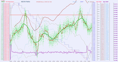
Reference unit (A9 PCB from HP3458A) is in DIY TEC thermostat, at +23.4°C +/-0.01°C.
Unit under test - my KX LTZ reference design is at ambient temp, battery powered.
Second module comparison
A9 Reference measurements, with various temperatures (constant +23.4, temp at which it was measured by calibrated last summer 3458A, ramp +23.4 to +46C in 0.1C/10 minute speed, constant +50C). Measured value is +7.184609VDC, so after a day of warmup calibrated my 3458A to CAL 7.184609VDC.
I could not figure out what is tempco of A9 Ref. It's stock module, no tweaks/mods. Originally I wanted to use K2002 in parallel to measure A9 ref value as well, but impedance of meter not high enough and cause ratio to change ~4ppm.
-
Anyone got working LTZ1000 board PCBs to sell?
-
Originally I wanted to use K2002 in parallel to measure A9 ref value as well, but impedance of meter not high enough and cause ratio to change ~4ppm.
Hello,
the K2002 has > 10 G input impedance in 20V range.
So even with worst case calculation of 5 Ohms for the zener you should get something in the ppb range and not PPM.
I think that one of your references picks up some RFI noise when connecting additionally antennas.
See the problem with my buffered output without 100nF capacitor where I have a "offset" of +3ppm without the capacitor.
https://www.eevblog.com/forum/metrology/ultra-precision-reference-ltz1000/msg846835/#msg846835
Unfortunately you have to be very carefully with capacitors on the output with the original datasheet cirquit.
(the current regulator may oscillate).
with best regards
Andreas
Edit: just measured the change between 10Meg and >10G on HP34401A (10V range LTZ#4) with the K2000 (100mV range) in differential mode (LTZ#4-LTZ#5).
it is around 0.3-0.4 uV for the 10 Meg input resistance.
A 1Meg Resistor across LTZ#4 gives 3.4uV change. (so less than 0.5ppm).
So we have less than 0.5 Ohms for the unbuffered zener voltage.
-
Likely you are right, as I used not shielded twisted cable wire to connect. I'll have to redo it better next try, to be sure.
-
Am I misunderstanding the schematic in https://www.eevblog.com/forum/metrology/t-c-measurements-on-precision-resistors/msg902577/#msg902577 or did CERN go with proportional-only temperature control? Any idea why? That would seem to me to add more temperature sensitivity.
-
Hello,
C80 gives some I-part to the controller.
But this is limited by the 330K resistor.
On the other side you have additional current amplification by the
power stage transistor T2 against the datasheet cirquit (A = 1).
Anyway: Without a capacitor from base to emitter of the sensing transistor Q2
the temperature controller is very noisy.
With best regards
Andreas
-
Not having a capacitor at the base of the sensing transistor should not be such a big problem with noise, at the low impedance there you can't effectively filter the LF noise from the zener reference anyway. Here the capacitor at the 7 V level might be more effective than at the sensing transistor. Still a capacitor there might be a good idea for EMI reasons.
The 330 K resistor in feedback makes this a proportional type controller - no more integral part left. The gain is rather high so it may not be a problem after all. Still it is well possible that the quality if temperature control is simply limited on how well the heater and sensor are placed inside the LTZ1000. You can't do better than that.
Still I don't think this modified version of temperature control is an improvement, more like a poor example. For example short time fluctuations on the temperature of the driving transistor and the diode would require the controller to react - so this may be a reason why a real integral part is not helping with that type of output stage. Also the 2.2 K resistor from the divider to the OP will slightly shift the temperature setpoint and in this sense makes the whole circuit sensitive to the temperature of the diode and transistor.
If I were to improve on the regulator part, I would try to compensate the square law of the heater, not to reduce regulator gain when the power goes down - this might give improvements at low heater power and should allow for twice the gain in the normal case, as there is no need for extra stability reserve at high power. With improved performance at low power one might consider a second level of regulation if really needed. With the often rather high temperature inside instruments this might be well something like a temperature controlled fan and suitable shielding against direct air flow of the sensitive parts.
-
Not having a capacitor at the base of the sensing transistor should not be such a big problem with noise, at the low impedance there you can't effectively filter the LF noise from the zener reference anyway.
Hello,
my measurements tell something other for the LF noise.
I get a reduction from 6mVpp to 0.6mVpp with the capacitor.
And also the sporadic dips of -40mVp are gone on the heater voltage.
with best regards
Andreas
-
Hello,
summary of my measurements with shortened legs on LTZ#4:
power supply current
edit: increased from 22.6mA to 24.0 mA (+6%) for LT1013Aincreased from 22.6mA to 25.2 mA (+12%)when changeing from LT1013A to LTC2057
PSRR 14-18.5V battery voltage
no significant change: from 0.076 ppm/V to 0.084ppm/V
Tilting LTZ#4
no significant change: from 0.25-0.31ppm to 0.26-0.29 ppm
Noise LTZ#4 unbuffered output:
from 1.19 uVpp to 1.05 uVpp in average (15 measurements over 100 secs)
T.C. of reference (without R9).
decreased from -5.1 ppm over 22 deg C (-0.23 ppm/K) to -2.1 ppm (-0.095 ppm/K)
so all in all:
higher power consumption, slightly lower noise (could be within statistics) and large reduced amount of T.C.
so I will try wether R9 = 402K will give near zero T.C.
attached the T.C. before shortening the legs and T.C. after shortening the legs.
Also attached the FFT of a noise measurement.
nothing unexpected here.
Above 10Hz the edge of the filter amplifier is seen. And of course some 50Hz mains hum.
with best regards
Andreas