
Author Topic: Transistors - die pictures  (Read 224888 times)

0 Members and 1 Guest are viewing this topic.

Offline mawyatt

  • Super Contributor
  • ***
  • Posts: 3566
  • Country: us
Re: Transistors - die pictures
« Reply #775 on: December 06, 2023, 02:05:13 pm »
Nice images and storyline Noopy :clap:

Thanks for the continual efforts in showing these great semiconductor images, along with the excellent storylines & analysis :-+

Best,
Curiosity killed the cat, also depleted my wallet!
~Wyatt Labs by Mike~
 
The following users thanked this post: SeanB, Noopy

Offline AnalogTodd

  • Regular Contributor
  • *
  • Posts: 100
  • Country: us
Re: Transistors - die pictures
« Reply #776 on: December 06, 2023, 02:08:31 pm »
Interesting story, beautiful pics, thanks!  :-+

Just out of curiosity, estimating R of a tin whisker:
R = \$\rho\$*L/S
\$\rho_{\mathrm{Sn}}\$ = 10.9E-8\$\Omega\$*m
L = 0.1mm
d = 5um

R = 10.9E-8 * 0.1E-3 / (3.14 * 25E-12 / 4) = 1.09/(3.14*1.25) = roughly 1/4 = 0.25\$\Omega\$  ???

I was expecting a much bigger R from such a thin wire.
When you're talking short distances, resistances turn out to be fairly low value. A gold bond wire that is 1mil diameter ends up at about 4.5 milliohm. What is the big deal on it isn't so much the resistance, but instead the fusing current. That's dependent on a number of variables from mass/cross sectional area to power dissipation and time. Sitting in open air like those will also lower the fusing current (over-molded bond wires can handle higher currents).
Lived in the home of the gurus for many years.
 
The following users thanked this post: RoGeorge, Noopy

Offline NoopyTopic starter

  • Super Contributor
  • ***
  • Posts: 1831
  • Country: de
    • Richis-Lab
Re: Transistors - die pictures
« Reply #777 on: December 06, 2023, 05:28:49 pm »
Thank you all for your input and positiv feedback!  :)

I had a small mistake in the name: It was called OC846A not OC864A.  :-+
 
The following users thanked this post: SeanB

Offline floobydust

  • Super Contributor
  • ***
  • Posts: 7225
  • Country: ca
Re: Transistors - die pictures
« Reply #778 on: December 06, 2023, 10:39:53 pm »

Here you can see the germanium power transistor OC864A, which was developed in the Funkwerk Erfurt but never went into series production. Only a few sample exist in the Thuringian Museum of Electrical Engineering (https://www.elektromuseum.de). The following background information also comes from this museum.

In 1959, the VEB Funkwerk Erfurt (FWE) ceased production of transmitter tubes. The capacities freed up were used to start developing germanium power transistors in the so-called Zentrallabor für Empfängerröhren (ZLE). An important basis for this work was a Soviet documentation. In addition to the necessary dimensions of the germanium crystal, it described how to etch the material, which alloy materials to use and which geometries to aim for. Alloying was carried out in a graphite mould under vacuum. The design of the alloying furnace was also taken from the Soviet documentation. However, the optimum temperatures and times for the alloying process were missing and had to be determined from tests. At the end of 1962, after the development had been completed, the results were transferred to the Halbleiterwerk Frankfurt Oder (HFO). [...]

"An important basis for this work was a Soviet documentation. "

High purity germanium crystal growing tech was a big deal back then. I'm curious who really had it or was it simply stolen IP?
Bell Labs 1953 William Pfann developed "zone refining" and I saw Japan using it to make transistors in the early 1950's.
 

Offline NoopyTopic starter

  • Super Contributor
  • ***
  • Posts: 1831
  • Country: de
    • Richis-Lab
Re: Transistors - die pictures
« Reply #779 on: December 07, 2023, 12:25:42 pm »
"An important basis for this work was a Soviet documentation. "

High purity germanium crystal growing tech was a big deal back then. I'm curious who really had it or was it simply stolen IP?
Bell Labs 1953 William Pfann developed "zone refining" and I saw Japan using it to make transistors in the early 1950's.


Well I don´t know. Would definitely be interesting...

Offline NoopyTopic starter

  • Super Contributor
  • ***
  • Posts: 1831
  • Country: de
    • Richis-Lab
Re: Transistors - die pictures
« Reply #780 on: January 26, 2024, 04:20:39 am »


This Siemens 2N3055 has two character sequences that could be a date code: 5E and S8. According to DIN EN 60062, the E would stand for the year 1974, S would refer to the year 1984. The Siemens 2N3055H from 1983 (https://www.richis-lab.de/2N3055_14.htm) is already printed with the modern four digit date code. This indicates that the 2N3055 shown here was manufactured in May 1974.


As in the Siemens 2N3055 from 1975 (https://www.richis-lab.de/2N3055_01.htm), there is a white powder in the package, which presumably is a drying agent.


The die is located on a base, which can also be seen on the back of the housing. The connection between the pins and the die is made with ordinary wires, not with bondwires. The wires are soldered on both sides.


The die shows the typical irregular surface of a hometaxial transistor. The wires were soldered directly to the metal layer.


The die is coated with a kind of protective varnish that peels off in some places.


A piece of the metal layer is missing at one point. There you can see what the openings in the passivation layer look like, through which the semiconductor is contacted.


The base-emitter junction only breaks down at -50V. High values are typical for hometaxial transistors. However, such high values have so far only occurred with 2N3055 transistors from Siemens.

A large part of the current flows in the upper range of the die (50mA, 100mA, 200mA).


https://www.richis-lab.de/2N3055_18.htm

 :-/O
 
The following users thanked this post: SeanB, Muxr, RoGeorge, ch_scr

Offline RoGeorge

  • Super Contributor
  • ***
  • Posts: 6483
  • Country: ro
Re: Transistors - die pictures
« Reply #781 on: January 26, 2024, 08:27:17 am »
As in the Siemens 2N3055 from 1975 (https://www.richis-lab.de/2N3055_01.htm), there is a white powder in the package, which presumably is a drying agent.

When we were kids, we were never discarding broken power transistors.  We were keeping them for their thermal paste inside.  They were easy to open by squeezing the cap a little, in a vice.  Smaller transistors were also having some thermal paste inside (e.g. the Ge type AC180/AC181), but way little than a TO-3 capsule.  The thermal paste was matte white, and slightly less thick than toothpaste, about the same as the white thermal paste available now for CPU radiators.  Though, I'm not sure is any of those power transistors I've opened were 2N3055.  Maybe they were Ge power transistors.  :-//

Could that white powder be, in fact, thermal paste solidified with time?
« Last Edit: January 26, 2024, 08:29:26 am by RoGeorge »
 
The following users thanked this post: exe

Offline NoopyTopic starter

  • Super Contributor
  • ***
  • Posts: 1831
  • Country: de
    • Richis-Lab
Re: Transistors - die pictures
« Reply #782 on: January 26, 2024, 02:53:15 pm »
I know that there is often thermal paste in smaller packages. Up to now I just have seen it in Ge transistors:


It makes sense to enhance the power dissipation from the die to the housing.

In TO3 packages I have never seen thermal paste. Just this one had a strange potting:


I´m not sure if thermal paste makes sense in a TO3 package. The thermal resistance through the base plate is quite low. I don´t think thermal paste would enchance that very much. On the other hand the upper part of the TO3 has a very high thermal resistance compared to the base plate and the heatsink. I don´t think you can dissipate a lot more thermal power if you enhance this path.
Are you sure you found the thermal paste in TO3 transistors?

On the other hand corrosion was quite a problem, so a drying agent absolutely makes sense. Often we saw something like a pill.
 
The following users thanked this post: SeanB, Muxr, RoGeorge

Online iMo

  • Super Contributor
  • ***
  • Posts: 4924
  • Country: vc
Re: Transistors - die pictures
« Reply #783 on: January 26, 2024, 04:24:50 pm »
Are you sure you found the thermal paste in TO3 transistors?
It is not a thermal paste.. It is an expressionistic vision of the late twentieth's century technology progress ("Controlled Currents in a Pot")..
 

Offline SeanB

  • Super Contributor
  • ***
  • Posts: 16349
  • Country: za
Re: Transistors - die pictures
« Reply #784 on: January 26, 2024, 06:10:38 pm »
GE transistors in TO3 and TO66 packages had the thermal paste, simply because the junction is lifted off the actual die attach, and the low temperature limit for Ge means any improved contact is desperately needed. Thus the compound, while a silicon planar transistor could get away with just having a soldered connection, and a drying agent to keep it dry and oxygen free, with the large silicon area providing enough thermal transfer, plus the max junction temperature of 150C as opposed to 70C helps a lot.

Got some genuine Newmarket transistors, courtesy of Sir Clive, in an unused and old amplifier kit, the infamous ones that were rather notorious because they were made from all reject transistors from the scrap test pile at Newmarket, bought by the ton by Sinclair, and binned into dead, sort of dead, sort of working and works good enough, at least at 15V. Might dig them up, though there are some Ge transistors in older packaging I also have around, OC36, unmarked as to manufacturer or date. Might have to open one and see what is inside.
 
The following users thanked this post: RoGeorge

Offline RoGeorge

  • Super Contributor
  • ***
  • Posts: 6483
  • Country: ro
Re: Transistors - die pictures
« Reply #785 on: January 26, 2024, 07:18:47 pm »
Are you sure you found the thermal paste in TO3 transistors?

It was very long time ago, maybe not TO-3, but certainly the same kind of capsule with a thick diamond shaped metal plate, like TO-3 use to have.  Could have been Ge power transistors, can't say for sure.  We were kids in the 5th grade or so, maybe it was some other goo inside, and we believed it to be thermal paste just like in the AC180/181K.  :-//

Offline SeanB

  • Super Contributor
  • ***
  • Posts: 16349
  • Country: za
Re: Transistors - die pictures
« Reply #786 on: January 26, 2024, 07:51:35 pm »
Well, took one and not so gently asked it to open up. Inside a clear sticky gel fill, not white, but still both a heat transfer compound and a protective blob. Rather interesting smell on opening, a faint smell that is similar to old oil, and showing the nice clean copper of the mounting and the copper top. Interesting is the wires in the package are made of a ferrous alloy, tinned outside.
 
The following users thanked this post: RoGeorge

Offline NoopyTopic starter

  • Super Contributor
  • ***
  • Posts: 1831
  • Country: de
    • Richis-Lab
Re: Transistors - die pictures
« Reply #787 on: January 26, 2024, 08:03:35 pm »
It seems I have to open some more transistors!  ;D
 
The following users thanked this post: SeanB

Offline Zoli

  • Frequent Contributor
  • **
  • Posts: 511
  • Country: ca
  • Grumpy old men
Re: Transistors - die pictures
« Reply #788 on: January 27, 2024, 08:19:47 am »
I vaguely recall seeing white silicone heat compound in ASZ15(Tunsgram); but that was around '79...
 

Offline NoopyTopic starter

  • Super Contributor
  • ***
  • Posts: 1831
  • Country: de
    • Richis-Lab
Re: Transistors - die pictures
« Reply #789 on: February 01, 2024, 07:41:16 pm »


The darlington transistor shown here was marked by Motorola with an application-specific label. The transistor came from a power supply of a CDC magnetic disk station. It was obviously manufactured in 1978.


The schematic of the power supply shows that it is a Darlington transistor.


The die is located on a round heatspreader and is protected by a transparent potting. The design is similar to the Motorola MJ3001 from 1979 (https://www.richis-lab.de/Bipolar60.htm), but the die is significantly smaller.


There is a dark line on the side of the heatspreader. The color appears unusual. Perhaps it is the remains of a flux which was applied before the die was soldered onto the heatspreader.


The potting is transparent, but distorts the view of the structures.


The potting can be removed very easily with the help of a silicone remover. In the bottom left corner, however, the potting adheres surprisingly strongly. Perhaps the material in this area has changed. The transistor had failed, so high temperatures may well have occurred locally.

The structures are typical of a medium-power Darlington transistor. The driver transistor is isolated to some extent in the top right-hand corner. In contrast to a normal transistor, the emitter contact is arranged in a U-shape around the base contact. From this emitter, the metal layer leads to the base area of the power transistor, which takes up the rest of the die. There, the base contact runs around the emitter as usual.

The size and design differ significantly from the Motorola MJ3001. This could be due to a different blocking voltage. The MJ3001 is specified with a blocking voltage of 80V. The transistor shown here only has to generate a 5V power supply from a 9V power supply.


The outer edges are etched down to create the familiar MESA structure, which ensures a clean base-collector interface. An edge can be seen on the surface of the MESA structure. This could be the passivation layer that protects the active areas of the transistor.


The driver transistor is surrounded by insulation trenches created with the MESA structure. The geometry extends the line between the driver and power transistor. As described in MJ3001, the base-emitter resistor of the driver transistor is located underneath this metal line.


The metallization of the power transistor is damaged in one corner. According to the visual impression, this is a manufacturing error and not a damage caused by an overload.


https://www.richis-lab.de/BipolarA49.htm

 :-/O
 
The following users thanked this post: SeanB, doktor pyta, exe, Muxr, RoGeorge, ch_scr

Offline NoopyTopic starter

  • Super Contributor
  • ***
  • Posts: 1831
  • Country: de
    • Richis-Lab
Re: Transistors - die pictures
« Reply #790 on: February 04, 2024, 07:47:42 am »


With the AT-32011, Hewlett Packard had a fast bipolar transistor in its portfolio. The AT-32011 is optimized for applications with low supply voltages in the frequency ranges 900MHz, 1,8GHz or 2,4GHz. According to the datasheet, the transistor is based on a self-aligned transistor process with a cut-off frequency of 10GHz. The maximum reverse voltage is 11V. The collector current must not exceed 32mA. In order to achieve a high cut-off frequency, a very high doping was selected, which is reflected in the low base-emitter breakdown voltage of -1,5V.


The edge length of the die is only 230µm. The labeling shows that Hewlett Packard developed the design in 1994. 320 appears to be the designation of the basic project, from which at least two bins emerge. In addition to the AT-32011, the datasheet also lists an AT-32033. The AT-32011 offers a slightly higher amplification factor than the AT-32033. The emitter connection is marked with an E, which is covered here by remnants of the bondwire.

The transistor structures themselves are too small to be resolved. They are located under the dark strip in the center, which is approximately 70µm x 15µm in size. The datasheet reveals that there are 20 emitters with a pitch of 3,2µm. The base connections are located between the emitter connections and both must maintain a certain distance from each other. This means that a resolution of less than 1µm is required in order to be able to image the structures to some extent. The comb-shaped contacts can just be guessed.


https://www.richis-lab.de/BipolarA50.htm

 :-/O
 
The following users thanked this post: SeanB, Muxr, RoGeorge, Miyuki, ch_scr

Offline NoopyTopic starter

  • Super Contributor
  • ***
  • Posts: 1831
  • Country: de
    • Richis-Lab
Re: Transistors - die pictures
« Reply #791 on: February 12, 2024, 05:10:20 am »


The Philips BLX15 is a RF power transistor in a SOT-55/3 package. In North America, it was distributed by Amperex, which belonged to Philips. The advertisement above is from Electronic Design 18 magazine from September 1973 and shows which transistors are optimised for which power and frequency classes. The BLX15 is the most powerful transistor in the 30 MHz frequency range.

The blocking voltage of the BLX15 is specified as 53V. The large gap to the maximum collector-base voltage is striking, it is specified as 110V. The datasheet allows a continuous collector current of 6,5A and a peak current of 20A. The cut-off frequency is 275MHz. The housing can continuously dissipate up to 195W power loss.
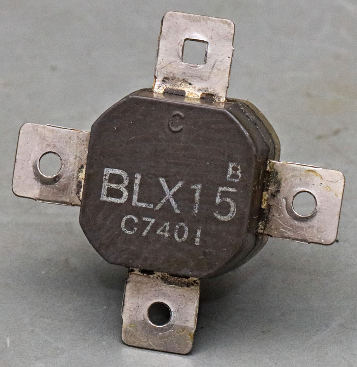


The BLX15 has four large contacts. The collector contact has a rectangular opening and is labelled with a C on the package. The emitter potential is led out to the right and left. The base potential is applied to the lower contact.
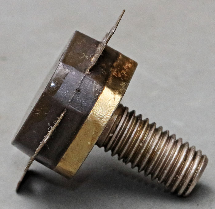


The transistor can be screwed into a heatsink with a thread. The thread merges into a thick metal plate. The upper part of the housing consists of two plastic elements, between which the connections are led out.
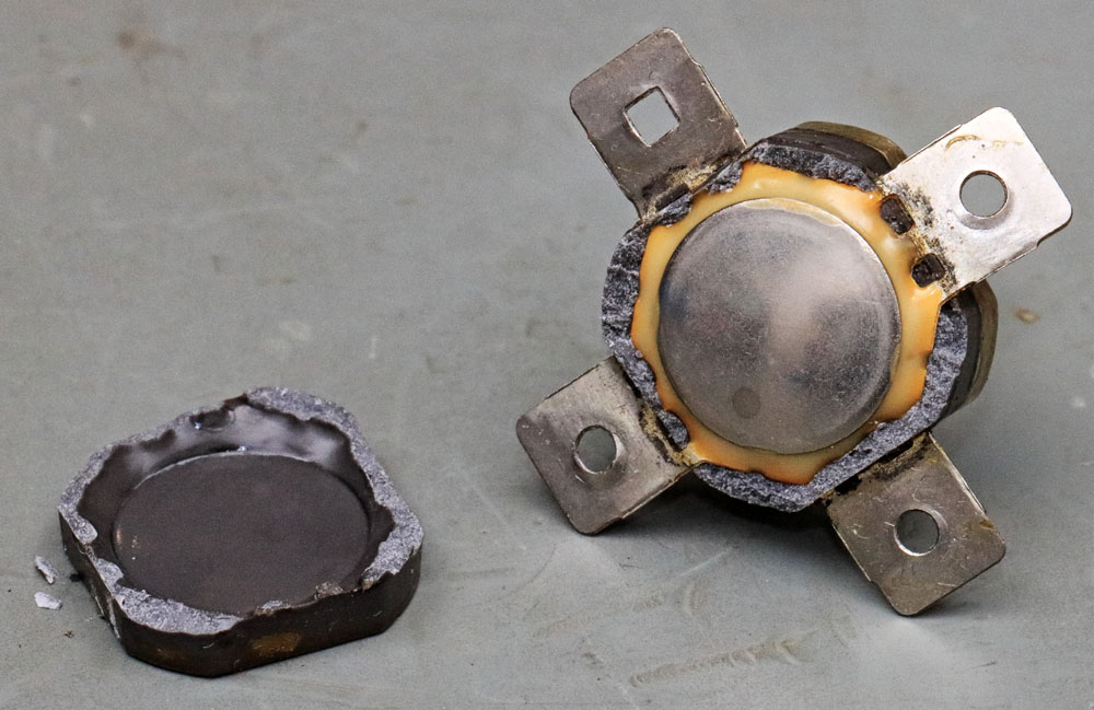


The upper plastic element can be broken off. Underneath is a metal cover that is glued to the package. This bond protects the semiconductor from the environment. The plastic housing itself is obviously not sufficiently sealed.
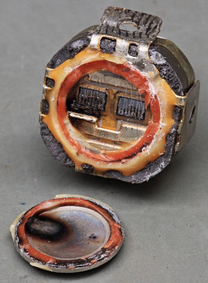


The cover can be removed from the housing with a knife. The transistor was declared defective. The damage is already obvious here. The left side of the cover and the corresponding area in the housing are heavily blackened. But there is also clear damage on the right-hand side.
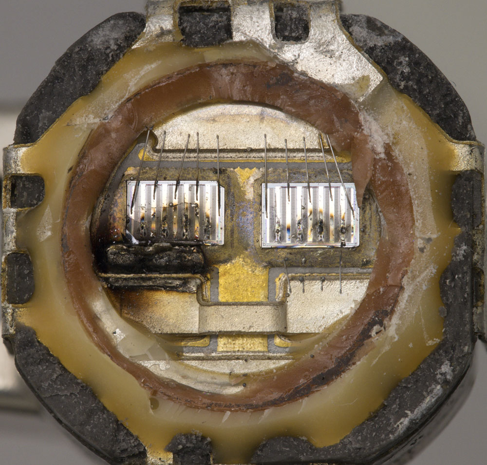


With a little more magnification, the structure of the BLX15 becomes clearly recognisable.
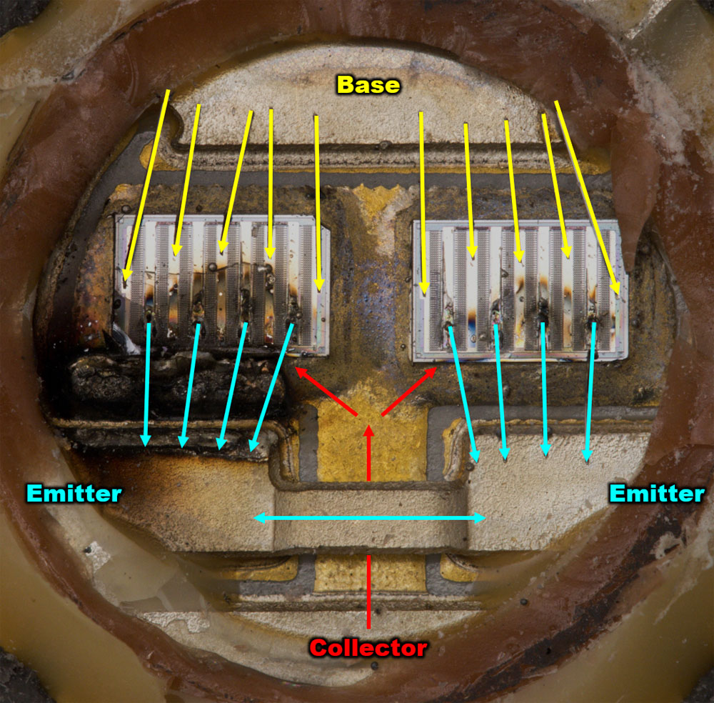


From below, the collector potential is fed to the transistors and led through the substrate into their active area. A metal bracket connects the emitter potentials supplied from the left and right. Four bondwires are available per transistor for the emitter current. The base current, which arrives from above, is even transmitted with five bondwires each.

The transistors are located on a ceramic carrier. This means that the BLX15 can be screwed into a heat sink without additional insulation. However, the ceramic slightly impairs heat conduction. It is remarkable that the datasheet nevertheless specifies a continuous power dissipation of 195W.
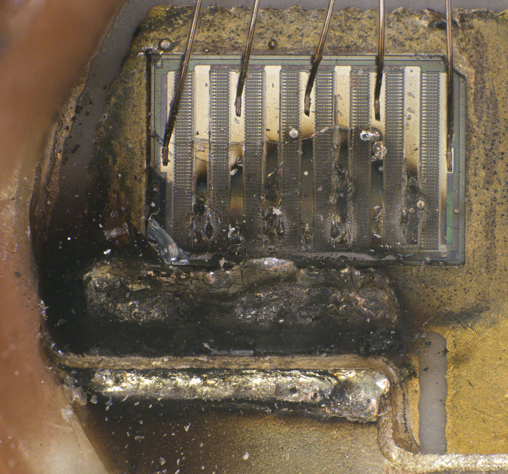


The bondwires on the emitter side of the left die have completely melted. An arc must have been burning for some time, as the edge of the metal rail also was melted considerably.
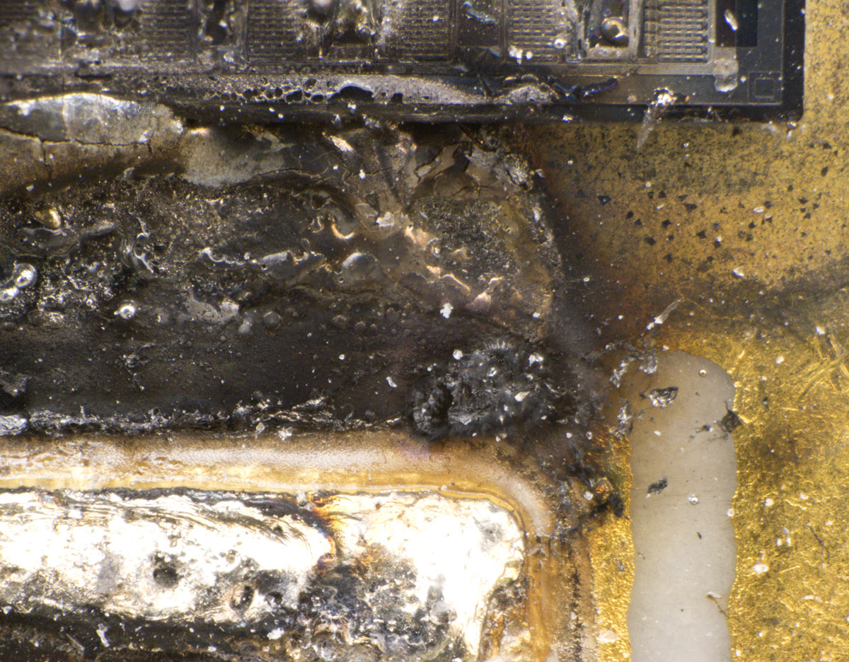


The insulation area of the ceramic is blackened over a large area. Metal has accumulated in front of the die. As the bondwires do not have that much volume, it must be material from the emitter bud bar.
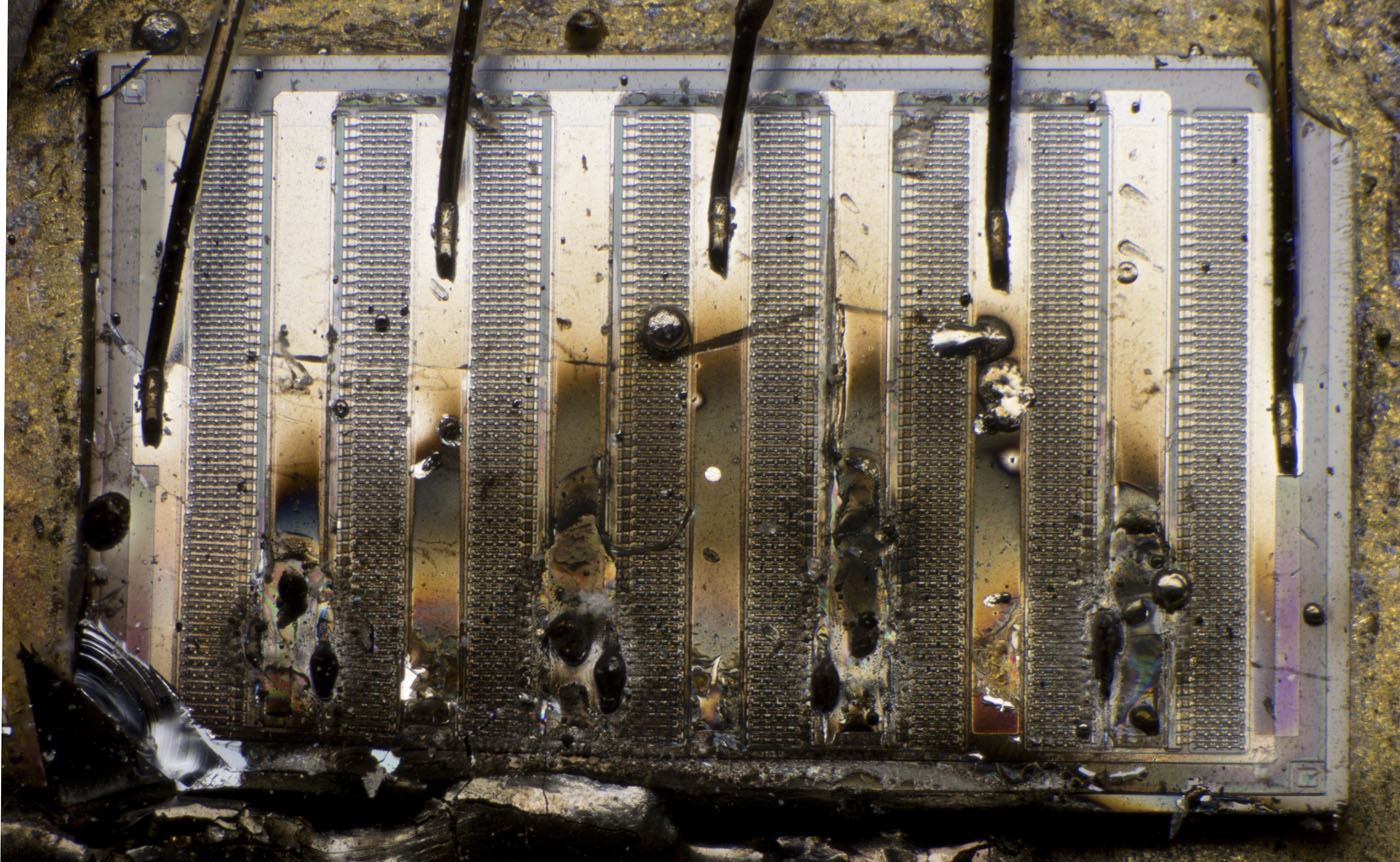


The energy input into the die was so high that the silicon broke in several areas. Nevertheless, the structure of the transistor can still be recognised. There are eight columns, each of which is grouped into pairs. The base current is supplied from one side of each column and the emitter current is dissipated on the other side.
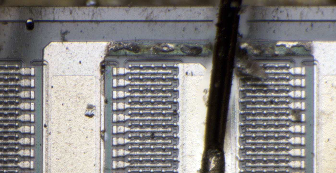


Obviously, there were high equalising currents between the gaps. The metal layer is completely destroyed in the upper area where it connected the gaps.
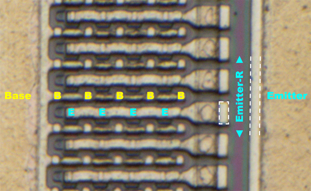


Each of the eight columns contains 52 rows, each with four emitter contacts. It appears to be an overlay transistor, as described in more detail in the 2N3553 (https://www.richis-lab.de/Bipolar22.htm). On the right, all rows are connected to a common resistor strip, which then leads to the emitter potential. The resistor strip ensures symmetrical current distribution across the rows.
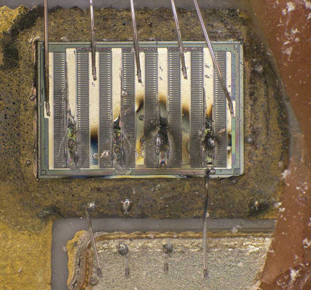


The right-hand side of the BLX15 is less badly damaged. All four bondwires are melted but still recognisable. The die is partially melted and discoloured in the area where the bondwires were attached, but the area around the transistor is still intact.
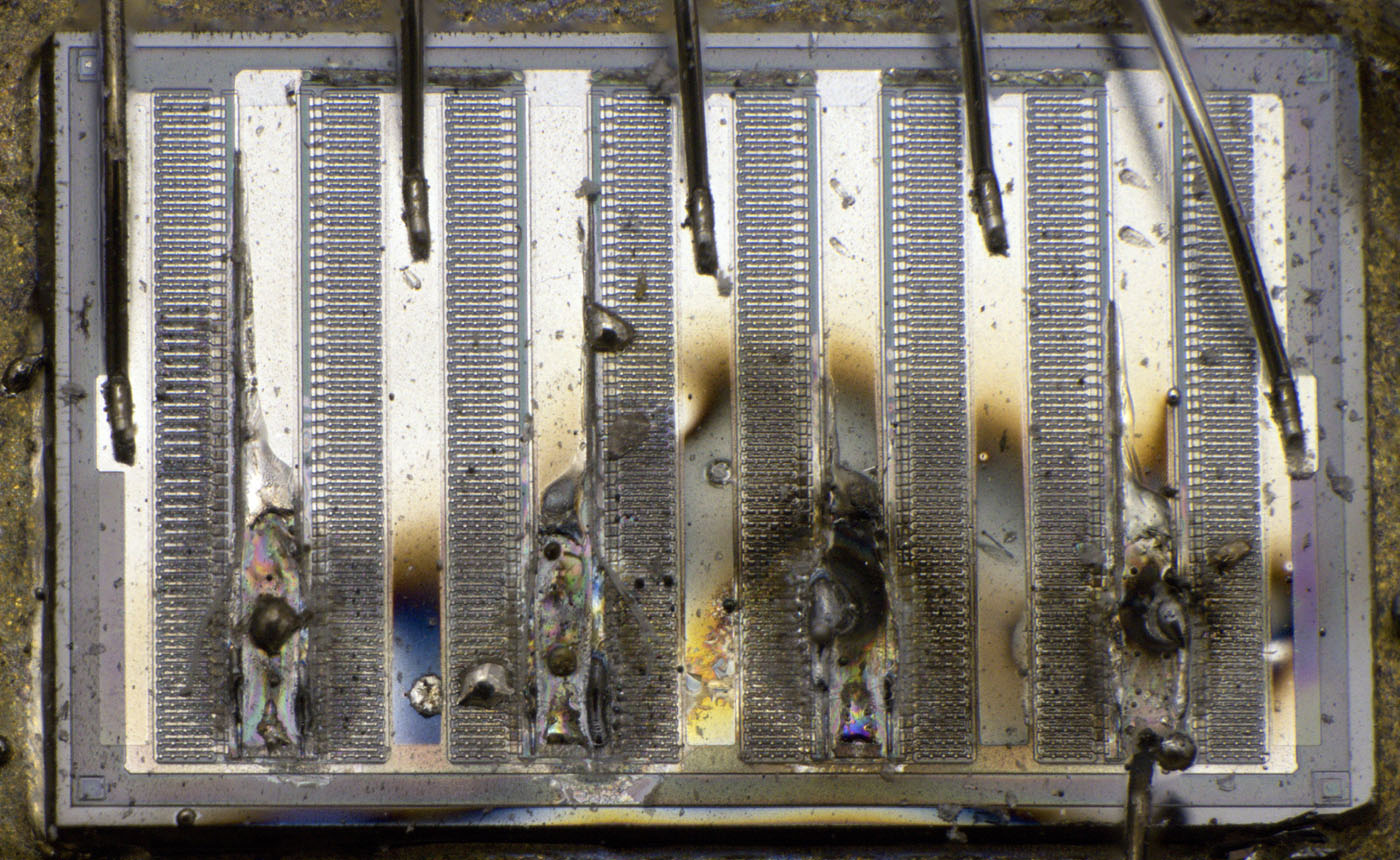


Here, too, all the connecting elements on the upper edge have been destroyed.
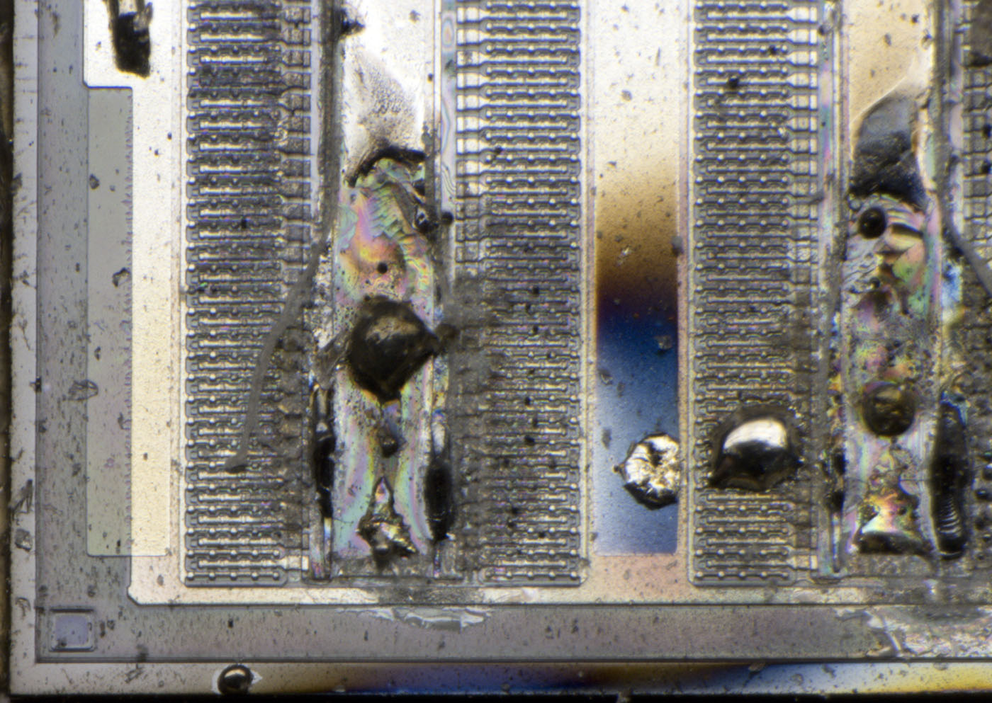


Where the bondwires made contact with the emitter potential, the metal layer melted over a large area.
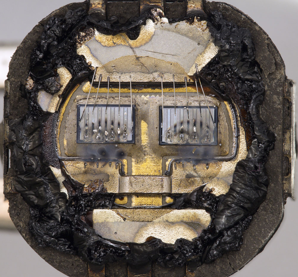


Here you can see a second defective BLX15. The package and labelling corresponded to the BLX15 above. The metal cover of this transistor was thermally opened.
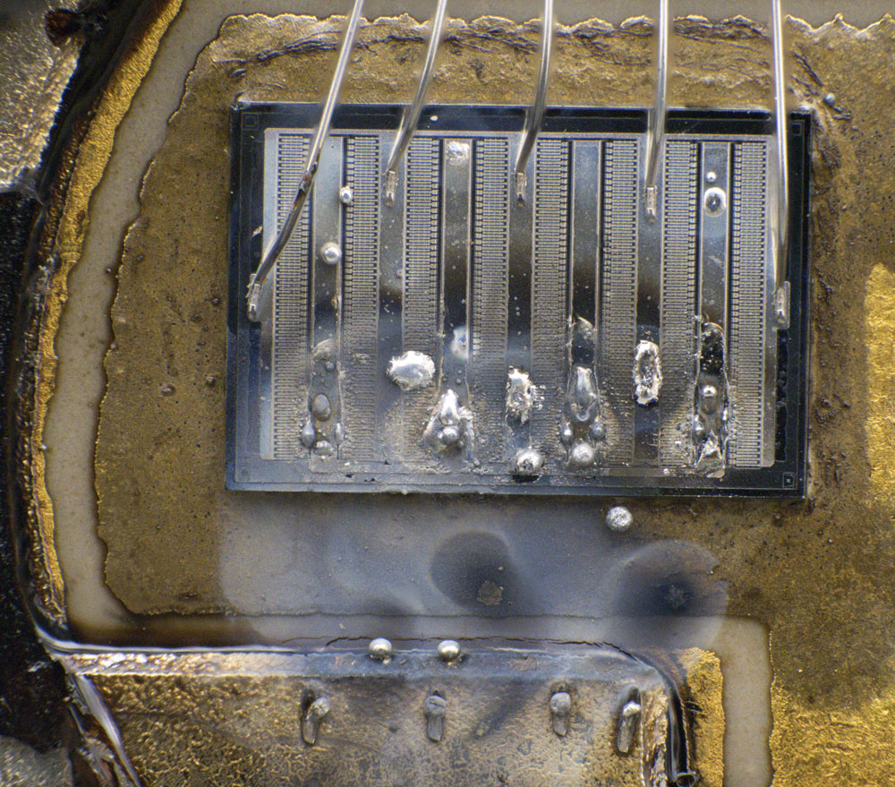
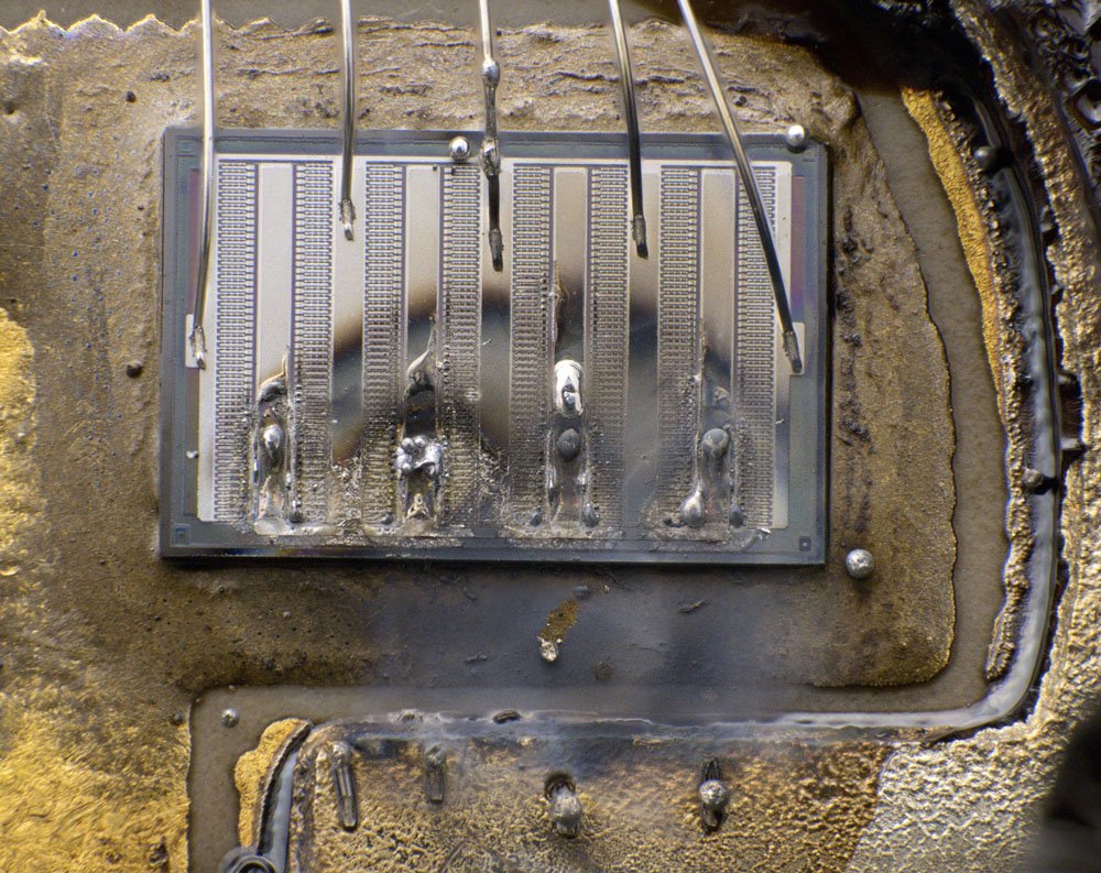


Here, too, both transistors are destroyed. The degree of destruction is slightly less severe. The emitter bondwires of both transistors are completely melted.
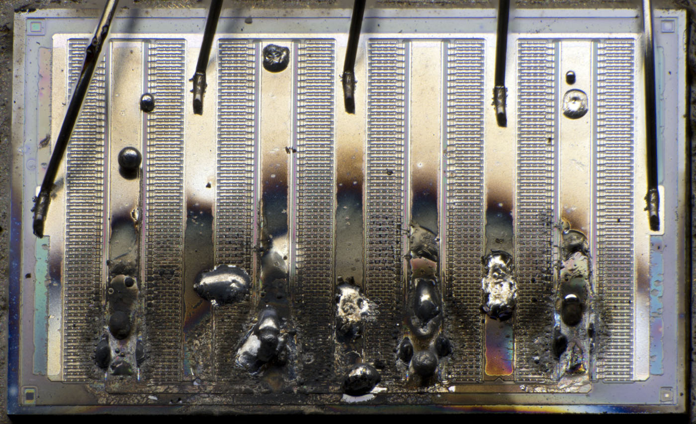
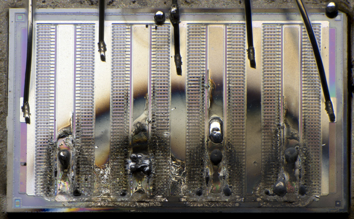


The transistors are constructed in exactly the same way as in the first BLX15. Here, the connections between the emitter areas are still intact.
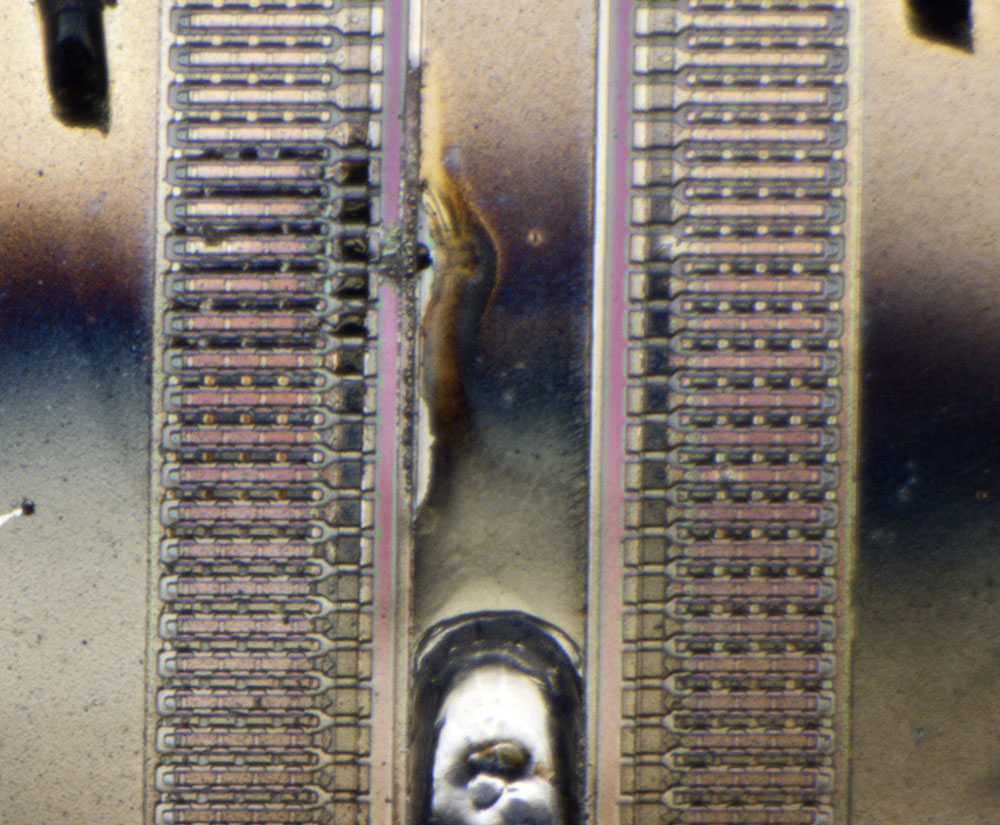


There is an artefact on the right-hand transistor slightly away from the bondwires that could be the starting point of the destruction. The emitter resistor between two emitter lines appears to have been destroyed locally, regardless of the surroundings. The collector line for the emitter current and some of the emitter lines have also melted in this area. Of course with such massive destruction, it is not possible to say for sure whether this was really the starting point of the failure.


https://www.richis-lab.de/BipolarA51.htm

 :-/O
 
The following users thanked this post: SeanB, Vgkid, Muxr, Wolfgang, RoGeorge, Miyuki, ch_scr

Offline NoopyTopic starter

  • Super Contributor
  • ***
  • Posts: 1831
  • Country: de
    • Richis-Lab
Re: Transistors - die pictures
« Reply #792 on: February 15, 2024, 07:02:45 pm »


Just a small transistor...
The BC178 is a PNP transistor that is the complementary type to the BC108. A manufacturer cannot be determined. 7244 could be a date code. The year of production would therefore be 1972, which seems plausible. The maximum collector emitter voltage is 25V. The current carrying capacity is 100mA continuous, 200mA maximum. The variant with the index A is specified with a current amplification of typically 180 (125-260). The cut-off frequency is 150MHz.


The structure of the transistor shows no special features. The edge length of the die is 0,34 mm. The silicon is broken at the lower edge.


https://www.richis-lab.de/BipolarA52.htm

 :-/O
 
The following users thanked this post: SeanB, Vgkid, Muxr, RoGeorge, ch_scr

Offline NoopyTopic starter

  • Super Contributor
  • ***
  • Posts: 1831
  • Country: de
    • Richis-Lab
Re: Transistors - die pictures
« Reply #793 on: February 15, 2024, 08:31:26 pm »
I talked to a guy who is very familiar with markings. He said this is probably a Valvo transistor.  :-+
« Last Edit: February 24, 2024, 08:29:07 pm by Noopy »
 
The following users thanked this post: SeanB

Offline NoopyTopic starter

  • Super Contributor
  • ***
  • Posts: 1831
  • Country: de
    • Richis-Lab
Re: Transistors - die pictures
« Reply #794 on: February 24, 2024, 08:58:31 pm »
Do you remember I once showed you some IRF3708? I now have some more and I have a different opinion if they are a genuine part or fake.

I won´t post all the pictures here because I´m to lazy.  ;D

Here we have a list of all the IRF3708: https://www.richis-lab.de/Transistoren_FET_IRF3708.htm


#1 to #3 are the old MOSFETs. Back then I thought that all of them are fake parts but since I found some IRF3708 with the same die as the #1 I assume this one is genuine.

#4a and #4b are interesting fake parts from AliExpress with two different transistors relabeled.

#5 and #6 look somehow strange as #1 but they all have the same die and came from different suppliers: Reichelt 2022, Reichelt 2013, Völkner 2022.

#7 finally looks like the datasheet describes the package. It was bought 2022 from ELV. The die is the same as in #1, #5 and #6 so approving that these are originals.


 :-/O
« Last Edit: February 25, 2024, 04:19:59 am by Noopy »
 
The following users thanked this post: SeanB, exe

Offline T3sl4co1l

  • Super Contributor
  • ***
  • Posts: 22019
  • Country: us
  • Expert, Analog Electronics, PCB Layout, EMC
    • Seven Transistor Labs
Re: Transistors - die pictures
« Reply #795 on: February 24, 2024, 11:50:54 pm »
I've suspected that they gave up on the HEXFET pattern a long time ago; it's possible they went with stripe (as basically? everyone else has) since, perhaps just the first generation or three even?  The name might then remain as the internal name for the chain of development, or as an IP scheme (trademark and related patents?).  All 2nd-source / substitute parts call theirs "planar stripe" or something to that effect, which I wonder if it was (at first?) a patent-evasion strategy, or just more suitable to their existing processes, or in fact the better way and everyone's converged on it now.  Well, the latter seems likely, heh.

Tim
Seven Transistor Labs, LLC
Electronic design, from concept to prototype.
Bringing a project to life?  Send me a message!
 

Offline NoopyTopic starter

  • Super Contributor
  • ***
  • Posts: 1831
  • Country: de
    • Richis-Lab
Re: Transistors - die pictures
« Reply #796 on: February 25, 2024, 04:24:06 am »
I had the same thoughts. Probably they changed the architecture and didn´t update the datasheet because for most people the electrical specifications are important not the architecture.  :-+

Offline NoopyTopic starter

  • Super Contributor
  • ***
  • Posts: 1831
  • Country: de
    • Richis-Lab
Re: Transistors - die pictures
« Reply #797 on: February 27, 2024, 04:27:12 am »
First additional information about the IRF3708:
It seems our thoughts were correct: International Rectifier changed their HEXFETs to "planar stripe HEXFET":
https://www.irf.com/pressroom/pressreleases/nr990728.html


Next: The Signetics NE543 is a servo motor driver. It supposedly corresponds to the WE3141, which was distributed by World Engines, a company from Cincinnati manufcaturing model kits. Perhaps the WE3141 was developed with Signetics and was later incorporated into the Signetics portfolio as the NE543.


There is a die in the housing, which also has bondpads in the centre. At the left edge of the die, you think you can recognise an image defect. However, this is actually a surprisingly wide edge.


It is difficult to visualise how slanted the edge actually is. It appears that the wafer was only cut very shallow and the rest was broken.


The dimensions of the die are 2,0mm x 1,8mm. On the right edge the characters 916A A are shown, presumably an internal project designation.


The datasheet shows a block diagram of the module and how it is usually wired. It is controlled with a square-wave signal via pin 4. The pulse width of the square-wave signal defines the setpoint position of the servomotor. Two inverters (yellow) process the input signal. The outputs of the inverters control a flip-flop (green) and are linked to the outputs of the flip-flop via NAND gates (purple). The lever of the servomotor is connected to a potentiometer. Depending on the current resistance value, the flip-flop generates pulses of different lengths. As a result, the NAND gates output pulses that are proportional to the deviation between the setpoint value and the actual value.

The NAND gates are followed by two circuits that extend the pulses of the flip-flop (cyan). The resistors Rs1 and Rs2 define by how much the pulses are extended. The resistors Rd1 and Rd2 ensure that the servomotor is only activated when there is a certain deviation between the setpoint and actual value. Finally, a second flip-flop (blue) realises the control of the two motor drivers (red), which represent an H-bridge. The resistors R8 and R9 improve the control behaviour of the circuit.


The datasheet also contains a circuit diagram of the module. The individual function blocks are highlighted here in the appropriate colours. An error has crept into the second buffer amplifier. Transistor Q2 has to be an NPN transistor. The circuit is largely self-explanatory. The only noticeable feature is the quadruple base contacting of the lowside transistors Q26/Q27 in the H-bridge.


The large H-bridge takes up more than half the area of the die. The transistors at the outputs of the pulse stretcher are just as prominent.


A closer look at the H-bridge shows that the circuit diagram does not quite reflect reality. The lowside transistors Q26 and Q27 each consist of two transistors. It is logical that each transistor has its own base resistor. However, it remains unclear why two base resistors have been integrated for each transistor.

The highside transistors Q24 and Q25 also each consist of two transistors. A PNP driver transistor is assigned to each highside transistor. However, the base potentials of the highside transistors are also connected in pairs.


https://www.richis-lab.de/BipolarA53.htm

 :-/O
 
The following users thanked this post: SeanB, Vgkid, T3sl4co1l, Muxr, RoGeorge, ch_scr

Offline NoopyTopic starter

  • Super Contributor
  • ***
  • Posts: 1831
  • Country: de
    • Richis-Lab
Re: Transistors - die pictures
« Reply #798 on: March 01, 2024, 03:43:42 pm »


The 2N3878 is a fast NPN power transistor in a TO-66 package. It blocks up to 50V, whereby the collector-base blocking voltage is significantly higher at 120V. The collector current may be 4A continuously and 10A for short pulses. With a collector current of 4A, the amplification factor is still at least 20. Up to 35W can be dissipated through the housing. The cut-off frequency is specified at 40MHz. At 4A, the 2N3878 enables switching pulses with a duration of 1µs.


The advertisement shown here is from the magazine Electronics from 1965.


The transistor is placed on an unusual heatspreader. The electrical contact is made with sheet metal elements that have been pushed onto the pins and then have been soldered to them.


The heatspreader appears to have been soldered into the base plate.


The contact plates are soldered directly to the die. The base potential (on the right side) is fed into the emitter surface via the metal layer. These conductor tracks are slightly thinner than those of the emitter. The entire structure is coated with a clear protective lacquer.


The transistor has a MESA structure with edges that are not completely straight. The surface of the transistor is partially irregular. A faintly recognizable edge separates the emitter area from the base area.


The surface is damaged in one spot. This appears to be a scratch that extends from the upper line of the emitter area to the lower line of the base area. In the lower area, the silicon is also damaged in addition to the metallization. However, the damage does not extend to the junction.


The base-emitter junction breaks down at -9V. The avalanche breakdown produces the familiar glowing dots. The current increases as follows: 10mA / 20mA / 30mA / 40mA / 50mA / 100mA / 200mA / 300mA / 400mA / 500mA

The light develops very evenly. However, the scratch seems to have an effect on the electric field. Below this artifact, the light spreads out late. In the lower left corner there are hardly any glowing islands. Since the metal layer with the base potential does not extend into this area, the resistance of the base-emitter path is higher there and the breakdowns in the areas with lower resistance remain dominant.


The infrared image shows the relationships that are described in more detail with the SF137 (https://www.richis-lab.de/Bipolar75.htm). In this image, the base current is 1A, while the collector current increases like this: 1A / 2A / 3A / 4A / 5A / 6A / 7A. The light initially only appears under the base area. As the collector current increases the light moves towards the emitter.


In this picture, the base current is just 0,5A. While the collector current rises to 8A, the transistor leaves the saturation area. The resulting high thermal load ultimately destroys the structures, which is shown by the emitter contact lighting up.


The damaged area can only be guessed at by a small discoloration. The protective lacquer, which is torn at the emitter contact, disturbs the view on the surface of the transistor.


https://www.richis-lab.de/BipolarA54.htm

 :-/O
 
The following users thanked this post: SeanB, Vgkid, RoGeorge, ch_scr, iMo

Offline NoopyTopic starter

  • Super Contributor
  • ***
  • Posts: 1831
  • Country: de
    • Richis-Lab
Re: Transistors - die pictures
« Reply #799 on: March 22, 2024, 04:53:06 am »


The International Rectifier IRLZ44 is a power MOSFET whose reverse voltage is specified at 60V. With a typical resistance of 28mΩ, a continuous drain current of 50A is permissible at room temperature. The IRLZ44 is a logic-level MOSFET. It achieves the resistance of 28mΩ at a gate-source voltage of 5V. For a gate-source voltage of 4V, the data sheet still specifies 39mΩ.

The marking can only be read easily with the correct illumination. The syntax and the layout of the marking match the representations often found in International Rectifier datasheets.


The die of the IRLZ44 is 3,6mm x 2,8mm. The gate potential is contacted on the left. The metal layer conducts the potential around the circumference of the transistor and also a little way into the center of the surface via two stubs.


As with many transistors from International Rectifier, several masks with numbers are shown on the upper edge. However, the structures are difficult to recognise here.


In the center of each edge is a small square of the metal layer. The purpose of these squares remains open, perhaps they facilitated the alignment of the masks or made it possible to check the alignment later.


A honeycomb structure can be seen in detail on the surface of the drain metal layer.


There is an older datasheet for the IRLZ44, according to which it is a third-generation HEXFET. In this datasheet, however, the device was not yet lead-free and lacked the index N. The P of this IRLZ44 shows that it is a lead-free device. An N is also appended to the designation. A more recent datasheet, which matches this marking, attributes the IRLZ44 to the fifth generation of HEXFETs. In any case, the honeycomb structure corresponds to the surface shown in the "International Rectifier HEXFET Databook".


https://www.richis-lab.de/FET38.htm

 :-/O
 
The following users thanked this post: SeanB, T3sl4co1l, RoGeorge, Miyuki, ch_scr


Share me

Digg  Facebook  SlashDot  Delicious  Technorati  Twitter  Google  Yahoo
Smf