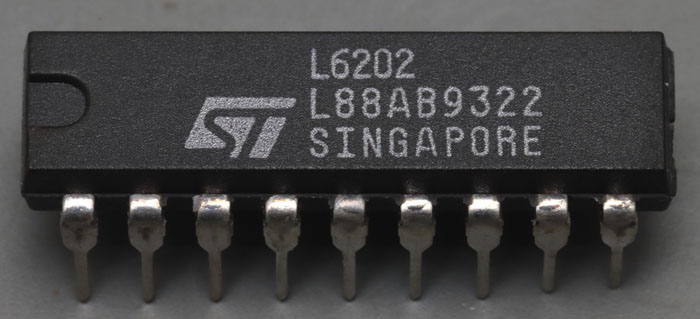
L6202 a famous H-bridge built by STMicroelectronics (SGS-Thomson to be honest). It´s more than a transistor but I have put it to the "special transistors".
In this Powerdip18 package, the device can carry up to 1,5Arms. Alternatively, a SO20 package is offered, but it allows just 1Arms. For higher power, a Multiwatt11 and a PowerSO20 package make it possible to conduct up to 4Arms. The peak current may increase up to 5A. The SO20 package is limited to 2A in this regard. The typical resistance of the switches is 0,3Ω. The maximum permissible supply voltage is 48V. The typical clock frequency is given in the datasheet as 30kHz, 100kHz is specified as the maximum. The L6202 ensures with a dead time of 100ns that never both switches are conductive at the same time.
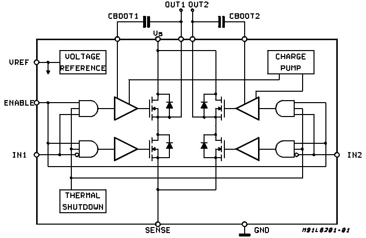
The block diagram in the datasheet shows the construction of the L6202. The H-bridge is built with four NMOS transistors. The negative potential of the H-bridge is isolated from the ground potential, so that a shunt for current measurement can be looped in.
According to the datasheet, the NMOS transistors are switched with a gate-source voltage of 10V. However, this also means that a separate supply voltage must be generated for the two highside transistors. This voltage can be obtained from two different sources. A charge pump ensures that the highside transistors can be switched on from a longer inactive phase. If switching gets faster, the charge pump would probably not be powerful enough. For this, bootstrap capacitors must be connected to the L6202, which lift the necessary larger amounts of charge to the high potential when the H-bridge is switched. According to the datasheet, the capacitance should be at least ten times as large as the input capacitance of the transistor, which is 1nF.
Four gates can be used to switch the two sides of the H-bridge. An enable input allows to switch off all transistors. An overtemperature protection switches the H-bridge off at temperatures above 150°C. The L6202 contains a 13,5V reference voltage source which must be stabilized externally with at least 220nF. One may then load the reference with up to 2mA.
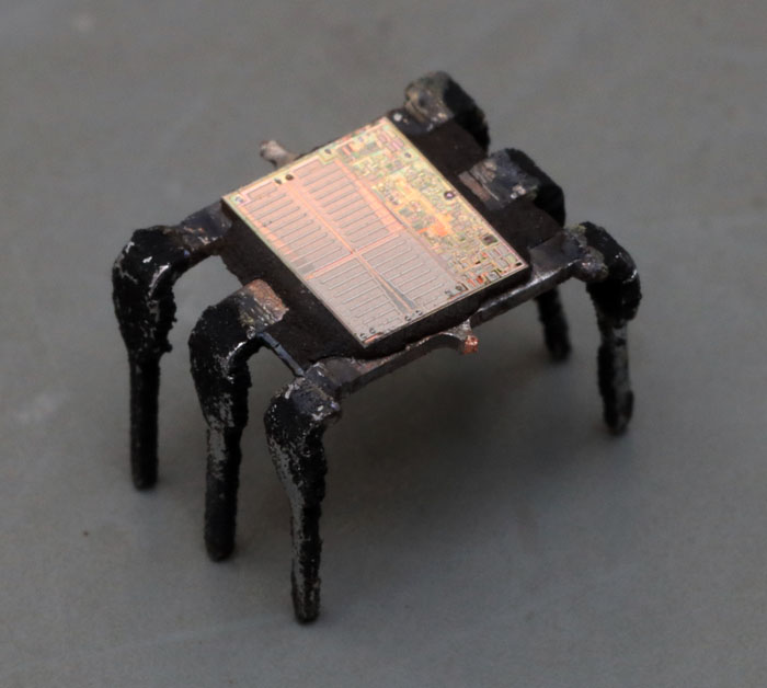
The six pins in the middle of the package are connected to ground. It can be seen that these pins are combined into a carrier on which the die is placed. This improves the power dissipation. Accordingly, the datasheet recommends connecting a large copper area to the six pins in the middle of the package.
The dimensions of the die are 5,1mm x 4,0mm. According to the datasheet, the device was manufactured with a BCD process. This allows the control circuit to be built with the benefits of bipolar and CMOS transistors, while high-performance DMOS transistors are used in the H-bridge. There are indications that the L6202 was the first device to be manufactured with a BCD process at STMicroelectronics, SGS-Thomson respectively.
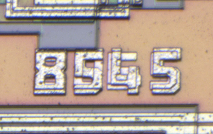
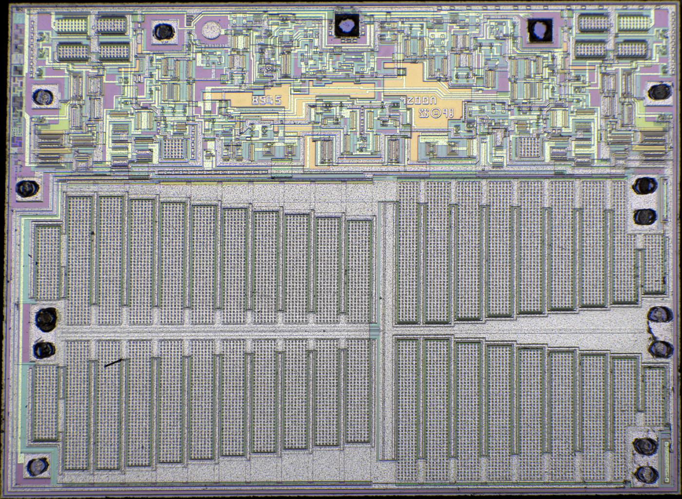
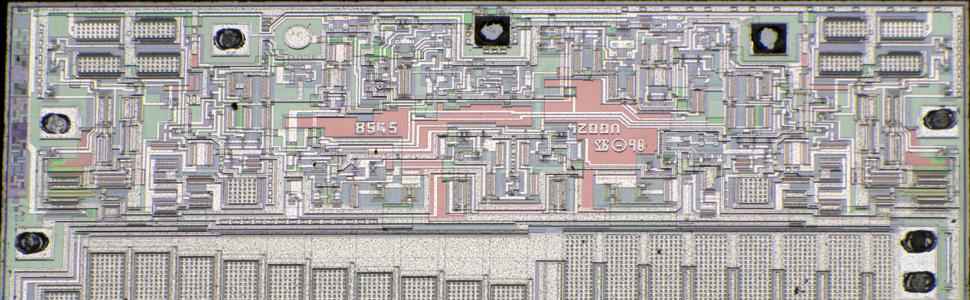
Somewhat to the left of center, several numbers are shown on top of each other. It seems that there are two metal layers used here. In the circuit itself, however, only one metal layer can be seen. The lower number is 8065, the upper 8545. The meaning remains unclear.
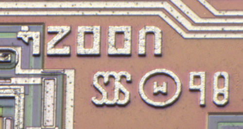
To the right of the center, the logo of SGS Thomson and the year 1986 are shown. The string U0024 could be an internal project designation.
On the left edge, there are some structures that allow to monitor the imaging performance of the process. The 13 squares could indicate a mask set with 13 masks.
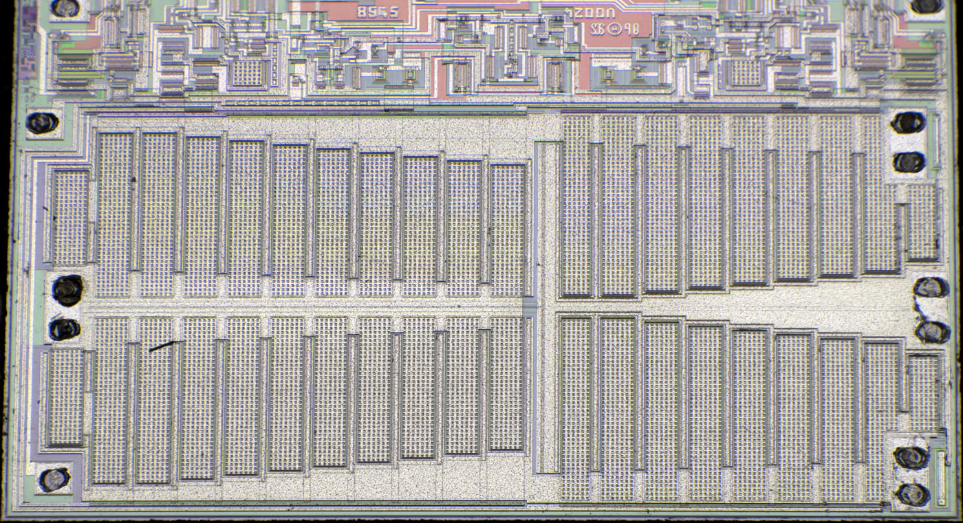
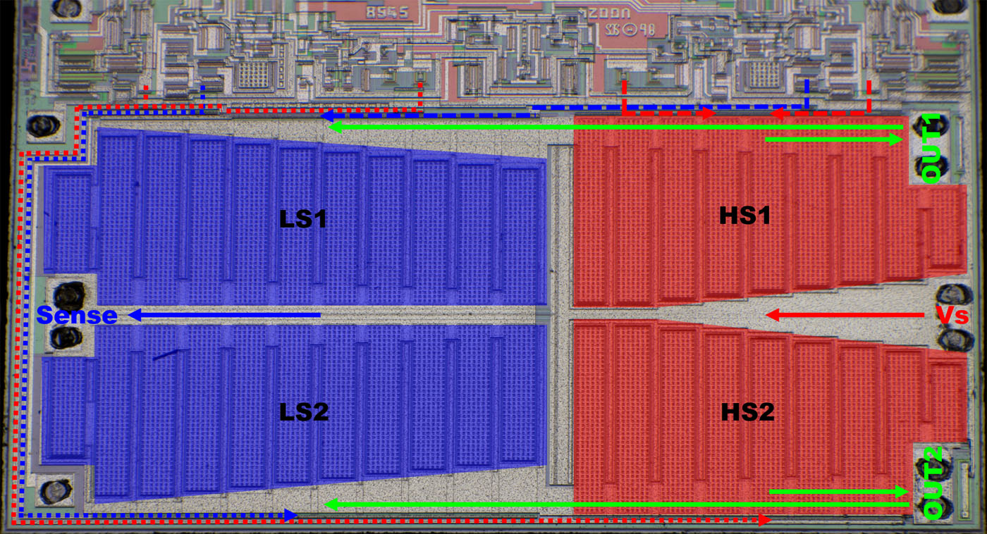
The interconnection of the four power transistors is clearly visible. The width of the lines is adapted to the respective local current. At first glance, the lowside transistors appear somewhat larger than the highside transistors. However, the highside transistors are slightly wider, resulting in approximately equal areas, as would be expected with four NMOS transistors. The gate potentials are fed from the top and from the bottom.
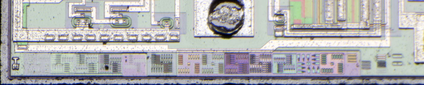
The control circuit is relatively clear. It is easy to see that each highside transistor is supplied from two areas. The charge pumps seem to be located in the center. Two very large, reddish areas are integrated there, which certainly represent the associated capacitances.
On the left and right edges, the bootstrap bondpads are placed respectively. In these areas is another control for the gate electrodes. Four larger elements are integrated in each of the corners. It could be that these are transistors that limit the gate-source voltage. After all, this voltage could approach the maximum permissible supply voltage of 48V.
https://www.richis-lab.de/FET30.htm 


