Input overload, Signal detail & fidelityAs the previous discussion shows, it would be desirable to have some hard facts. This is why I’ve done some tests using my old Siglent SDS1104X-E, Hardware 00-02, Firmware 6.1.37R8.
As always, we need to characterize the test signal first; it is a 1 Vpp 10 Hz square wave with 50 ns rise time (arbitrarily set). The reference measurement has been made with a Picoscope 4262, which has at least two unique advantages over other instruments:
• True 16 bit performance
• No split path input buffer, hence none of its inherent problems
As a consequence, we can capture the signal correctly without overloading the scope input and then use zoom to inspect the details:
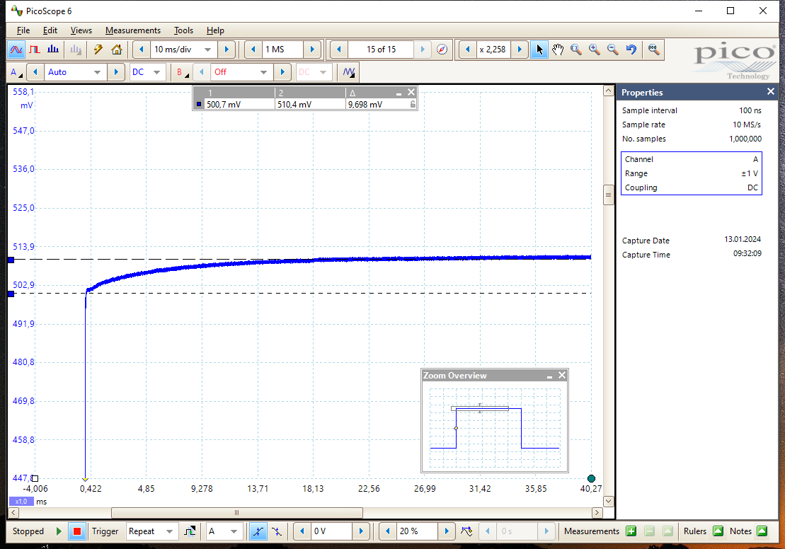
Pico4262_Square_10Hz_Zoom
As can be seen, the square wave is not perfect indeed. The top is not entirely flat and has an aberration of ~9.7 mV, resulting in a maximum error of 0.97%.
In order to avoid overloading the input of an SDS1104X-E, the signal amplitude must not exceed 1 Vpp. At 100 mV/div, the 1 Vpp signal already exceeds the screen height, but this is still no problem. It is a problem though that the SDS1000X-E series is a strict 8 bit DSO. Consequently, it doesn’t provide vertical zoom, because even without any zoom half the screen height would already be enough to show all the captured detail.
There is a little trick though, (with regards to LeCroy who used the Identity math function to provide zoom). Unfortunately, the SDS1104X-E has just the most basic math operations and certainly no Identity function. But we can substitute that by an addition: if we use the Ch.X + Ch.X operation, we get 2 x Ch.X, i.e. twice the amplitude of the otherwise unchanged input signal. Taking this into account, we can just double the intended vertical scale setting for zoom, e.g. use 20 mV/div when we originally intended to use 10 mV/div:
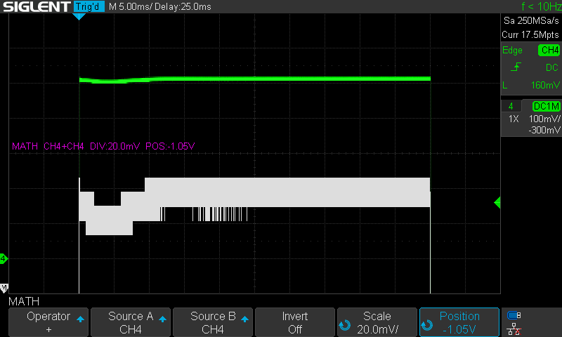
SDS1104X-E_Square_10Hz_Math
Yet that’s certainly not what we have hoped for. The math result is still only 8 bits and at 10 times magnification, noise also becomes noticable. Even HIRES and Average acquisition modes are truncated to just 8 bits, but at least they help to get rid of the noise.
Average is the preferred mode as it doesn’t affect the bandwidth, yet it requires a repetitive signal, as is the case here.
ERES on the other hand can be used on single shot recordings, but it limits the bandwidth – which might even be desirable in certain scenarios.
The same zoom result with Average 64 acquisition:
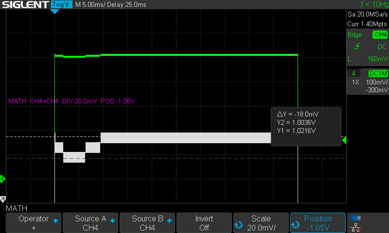
SDS1104X-E_Avg64_Square_10Hz_Math
Now that the noise is gone, we can measure the aberration: it is about 18 mV. Since we’re measuring 2 x Ch.4, we need to divide by two and get ~9 mV, which conforms to the reference measurement quite nicely.
Yes, the waveform is not quite the same as the reference, because we see a kind of overshoot at the beginning. This is one of the problems of the split path input buffer; it is in the recombination of the LF and HF path, which have significant runtime differences. Such effects will be visible whenever the crossover frequency of the split path buffer falls somewhere in the middle of the signal spectrum, causing pulse distortions because of the non-constant group delay.
All that said we should never forget about the dimensions we’re talking here: an aberration of less than one percent of the signal amplitude – this is much better than e.g. the DC accuracy specification of the instrument. And even expensive scopes can show overshoots up to 10% - not many manufacturers are brave enough to put these figures in their spec sheets though.
We can now try overloading the input step by step and see if we still get correct results, e.g. five times overloading by using 20 mV/div:
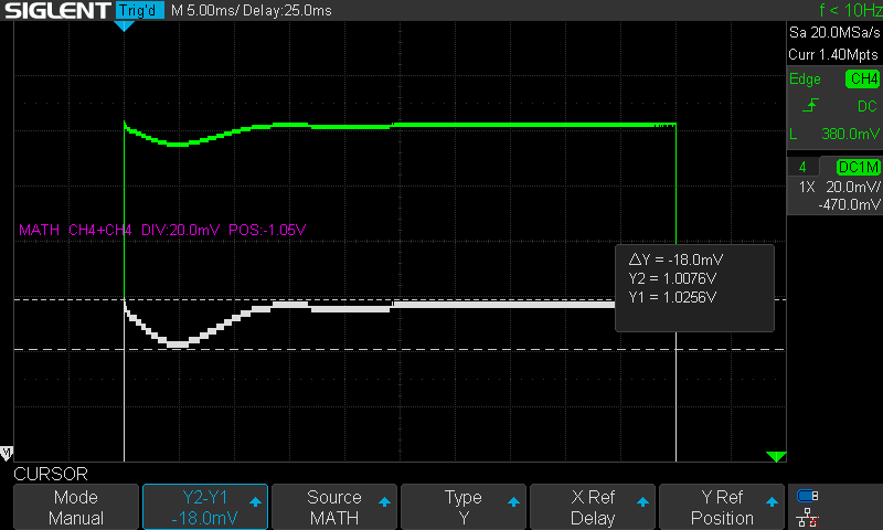
SDS1104X-E_Avg64_Square_10Hz_Math_OVD5
Now there should be enough detail already and the measurement is still correct.
We can take it one step further, get rid of the math channel and switch back to normal acquisition mode:

SDS1104X-E_Square_10Hz_OVD10
Conclusions: Even though in this special case the waveform isn’t reproduced 100% accurately, the aberration is less than one percent, hence nothing to complain about, especially not for a cheap bottom entry level scope like the SDS1104X-E.
By contrast, an SDS2000X HD is much closer to the truth (<0.1% aberration). It needs not be overdriven as it has 12 bits from the outset, together with high resolution math and vertical zoom. The SDS2000X Plus is only 8 bits physically, but it has high-res math, thus can provide similar results.
In particular the upcoming SDS800X HD will have all the relevant features of the SDS2000X HD, thus being much less restricted than the SDS1000X-E series and that for a really low budget.

SDS2504X_HD_Square_10Hz_Zoom_Avg64


