-
However, I wanted to take the time to understand the circuit at little better, and get a feel for what the components in that list (or elsewhere on the board, if needed) are supposed to do in that circuit. I figure if I can understand a component's role, then why Tek selected the parts they did during the original design should become apparent, and therefore inform what currently-available parts would best serve as replacements in that role. For all I know, that list is still current. But, I'd like to understand why, as opposed to just blindly throwing a bunch of parts on a board.
Wise approach.
Today there are better components available than the designers had available however as always the cost of the BOM always guided component choice.
But there are some traps where existing component characteristics must be carefully considered before any substitution can be made. -
Today there are better components available than the designers had available however as always the cost of the BOM always guided component choice.
But there are some traps where existing component characteristics must be carefully considered before any substitution can be made.
I had suspected that was the case. I recall reading about how some linear power supplies in older audio gear were susceptible to becoming unstable if new caps with too low an ESR were substituted, as the design and layout considerations of the time, coupled with the characteristics available at the time, caused the power supplies to somewhat dependent on the not-so-great-today ESR specs of the the then-acceptable capacitors for stability.
In the case of these Tek 24xx series power supplies, are you aware of gotchas in component substitution? Anything that if substituted with a part with supposedly better specs would actually work against the goal of a stable, clean, supply voltage with sufficient amp capacity? -
In the case of these Tek 24xx series power supplies, are you aware of gotchas in component substitution? Anything that if substituted with a part with supposedly better specs would actually work against the goal of a stable, clean, supply voltage with sufficient amp capacity?
Not 24xx in particular but study these posts where a member battled with FET Millar capacitance after selecting a replacement.
Start here:
https://www.eevblog.com/forum/repair/tektronix-2215-scope-repair/msg1647551/#msg1647551
Then jump to here:
https://www.eevblog.com/forum/repair/tektronix-2215-scope-repair/msg1824401/#msg1824401
Then read a few more posts.
I found it quite interesting and it just proves there are hidden traps for the unwary especially when just dropping a substituted component in and not understanding or modifying the design to account for it. -
If you follow the procedure as posted here and use the parts listed you will have no issues when re-capping the PSU:
https://www.eevblog.com/forum/testgear/tektronix-2465b-oscilloscope-teardown/msg1658102/#msg1658102
And also here is an alternative procedure for calibrating the Counter option if required:
https://www.eevblog.com/forum/testgear/tektronix-2465b-oscilloscope-teardown/msg1937605/#msg1937605
Edit, forgot to include parts list. See attached.
-
...
Another thing I note is that I don't have the famous Dallas battery-backed SRAM, as seen on the later, SMD-style A5 boards. This thing looks like a plain battery, not a RAM-chip or ROM chip of any kind, especially given it's only 4 pins on the board. Apologies for the blurry photo there, but it looks like there's some dried flux residue on those solder joints. I don't know if that's normally there, or if that means that this board has been worked on before, and the battery has already been replaced once. It's hard to tell, given the lack of date codes on the label. I'll have to compare the A5 boards in my other pre-B5xxxx scopes.
Others have reported flux residue on their batteries. Although these batteries are rated for wave soldering (temporary short and elevated temperature), maybe Tek decided to be ultra-conservative and mount them afterwards anyway. -
I'm not sure what this board is, or what it does. I do believe it is a standard board, as when I opened up B0120xx for comparison, it also had this board in it. Whatever it is/does, it fits in the central cavity of the scope, between the option boards and metal wall, and has a ribbon cable that goes through the floor of the central cavity and connects to the A1 board. I was going to leave it in place, initially, but I found it easier to get at the power supply assembly with both hands with it out of the cavity.
That's the A4 readout board, responsible for the on-screen text and cursor display generation. The labeled chip in the middle is the character ROM (actually an EPROM). There's a giant section (10 pages) in the theory part of the service manual on how this board works, if you're curious.
(Attachment Link) (Attachment Link) -
That's the A4 readout board, responsible for the on-screen text and cursor display generation. The labeled chip in the middle is the character ROM (actually an EPROM). There's a giant section (10 pages) in the theory part of the service manual on how this board works, if you're curious.
Interesting. I remember seeing an easter egg of Tetris, or maybe it was Centipede hidden on an HP scope, so perhaps I shall have to dump the ROM and see what secrets lurk therein. At a later date, though.If you follow the procedure as posted here and use the parts listed you will have no issues when re-capping the PSU:
https://www.eevblog.com/forum/testgear/tektronix-2465b-oscilloscope-teardown/msg1658102/#msg1658102
Thank you. I took a look at that and will remember that as a reference. A thing I recall from this thread was a caveat about one of the capacitors on one of the power supply boards being wrong on the schematic or the board, or the schematic swapped them, or something like that. However, I notice the power supply from your 2465 in that link looks different from mine; the capacitors are laid out slightly differently. Nonetheless, I agree with your admonition in that link; it makes sense to replace the capacitors one at a time.In the case of these Tek 24xx series power supplies, are you aware of gotchas in component substitution? Anything that if substituted with a part with supposedly better specs would actually work against the goal of a stable, clean, supply voltage with sufficient amp capacity?
Not 24xx in particular but study these posts where a member battled with FET Millar capacitance after selecting a replacement.
Start here:
https://www.eevblog.com/forum/repair/tektronix-2215-scope-repair/msg1647551/#msg1647551
Then jump to here:
https://www.eevblog.com/forum/repair/tektronix-2215-scope-repair/msg1824401/#msg1824401
Then read a few more posts.
I found it quite interesting and it just proves there are hidden traps for the unwary especially when just dropping a substituted component in and not understanding or modifying the design to account for it.
Quite interesting indeed. I hadn't thought about miller capacitance in a while; last time I read about it was how it applied to audio amplifiers. But seeing how it can mess with the inverter gate drive in an SPMS is a good thing to realize. Hopefully none of the components in the gate drive section have been damaged, because it seems like drive mosfets with sufficiently low miller capacitance can be kind of hard to find.
On the topic of replacement components, I want to talk about going high and low from the original spec.
There is a pair of 15Ohm, 1/2W carbon film resistors parallel with the NTCs (R1010 & R1019) as part of the inrush protection mechanism. In the work I've read on this so far, I've seen people up-rating them and replacing them with 3W resistors or the like. Clearly, these are subject to some degree of thermal stress, being inline with with the mains before it enters the first rectifier. Is this necessary, or is it a bit of an insurance policy to make sure they don't fail and thus cause a cascade of failure in more expensive parts? Or is upgrading these resistors risking the failure of more expensive parts by causing what was intended as a sacrificial component to not fail when it should?
Additionally, I note that in both of the Pre-B05xxxx supplies I've seen so far, one or both of resistors R1016 and R1018, have been burnt by failures of C1015 and C1018. I find myself wondering if perhaps it wouldn't be a good idea to increase those from 1/2 watt thermal ratings to something higher. My understanding from reading about X and Y ratings for caps is that an X-rated capacitor is supposed to fail shorted, with the idea being that in doing so it would cause a breaker to trip or a fuse to short. By my reading, resistors typically fail open. So of C1015 or C1018 fails, and draws the full mains current across R1016 or R1018, forcing them to release their magic smoke and become open in short order. Do we want to preserve that short so fuses start blowing? Or are these resistors intended as sacrificial components, and thus supposed to self destruct in the presence C1015 or C1018 shorting? In which case, would it be a good idea to go for a lower thermal rating so the resistor blows even sooner? Or is 1/2W the smallest thermal rating that could fit in that role?
Or am I over thinking this and the job of these resistors is simply to be part of the RLC filters across the mains before the rectifier, 1/2W was the cheapest size appropriate for the role, and it should be left alone or replaced with like? -
@ Koreth
Much depends on the engineer of that time and the % rating he/she was permitted to use when determining the W rating of components selected plus the always overarching concern of the BOM cost.
When we are reworking old instruments the time spent and the cost of replacements in no way can be related to the original BOM so were possible it does no harm to uprate componentry especially resistors in the power sections unless they are low % tolerance where it is wise to match the BOM.
Back to % ratings, a designer these days may choose to subject components to close to their full rating whereas in years gone by they were more conservative with lower stresses placed on components namely for better long term reliability particularly for silicon however manufacturing processes today have in general made most components more reliable.
A retired Dr EE buddy told me for Telco designs he wasn't to subject ANY componentry beyond 63% of ANY of its ratings. Today much has changed and for us all we need consider what % rating we need limit ourselves to for long term reliability of designs.
To use an old saying; we are each masters of our own destiny.QuoteThere is a pair of 15Ohm, 1/2W carbon film resistors parallel with the NTCs (R1010 & R1019) as part of the inrush protection mechanism. In the work I've read on this so far, I've seen people up-rating them and replacing them with 3W resistors or the like. Clearly, these are subject to some degree of thermal stress, being inline with with the mains before it enters the first rectifier. Is this necessary, or is it a bit of an insurance policy to make sure they don't fail and thus cause a cascade of failure in more expensive parts? Or is upgrading these resistors risking the failure of more expensive parts by causing what was intended as a sacrificial component to not fail when it should?
Yes, preventive replacement.
With SMPS the startup behaviour is crucial and it must be predictable so to not let the silicon magic smoke escape.QuoteAdditionally, I note that in both of the Pre-B05xxxx supplies I've seen so far, one or both of resistors R1016 and R1018, have been burnt by failures of C1015 and C1018. I find myself wondering if perhaps it wouldn't be a good idea to increase those from 1/2 watt thermal ratings to something higher. My understanding from reading about X and Y ratings for caps is that an X-rated capacitor is supposed to fail shorted, with the idea being that in doing so it would cause a breaker to trip for a fuse to short. By my reading, resistors typically fail open. So of C1015 or C1018 fails, and draws the full mains current across R1016 or R1018, forcing them to release their magic smoke and become open in short order. Do we want to preserve that short so fuses start blowing? Or are these resistors intended as sacrificial components, and thus supposed to self destruct in the presence C1015 or C1018 shorting? In which case, would it be a good idea to go for a lower thermal rating so the resistor blows even sooner? Or is 1/2W the smallest thermal rating that could fit in that role?
Sacrificial resistors IMHO.
-
Looking at this parts list, I find myself questioning the the changes in voltage or capacitance.
For example let's take the filtering capacitors hanging off the output of the inverter transformer, C1110, C1111, C1113, C1114, C1115, and C1116. The originals are a blend of 180 and 250 uF. 330 seems like a bit of a jump, moving the poles of the LC filters the form from 2.2 kHz and 1.9kHz to 1.6kHz. That, I'm less worried about, since I don't see knocking an extra few dB off the ~41Khz switching noise as a particularly bad thing, and I don't think the increase in charging current from the increase in capacitance would load down the inverter too much more. However, is there not a consideration on undercharging electrolytic capacitors shortening their life? Per the voltages in the diagram, the stock 180uF caps on the +/- 15V lines, at 19.2V at this point in the circuit are being charge up to about 48% of their max voltage, and the 250uF caps on the unregulated +/- 5V lines (at 7.1V) are being charged up to about 35%. However, with the 50V rating on the proposed parts list, those unregulated lines are only being charged up to 14% of their rating. Is this too low of a charge for a healthy cap life?
I'm not saying these are unreasonable choices, given the choice of the Panasonic EB series. Looking on the datasheet, 330uF was the smallest value that wasn't lower than the original value 250uF caps. However, 220 uF is available to replace the 180 uF 40V, and a 220uF 50V is cheaper than 330uf 50V. Was this part selection driven somewhat by a desire to keep the parts list small and simple? -
Looking at this parts list, I find myself questioning the the changes in voltage or capacitance.
While I've not analyzed the design there are more important consideration for SMPS cap selection than primarily capacitance or for that matter even voltage headroom.
For example let's take the filtering capacitors hanging off the output of the inverter transformer, C1110, C1111, C1113, C1114, C1115, and C1116. The originals are a blend of 180 and 250 uF. 330 seems like a bit of a jump, moving the poles of the LC filters the form from 2.2 kHz and 1.9kHz to 1.6kHz. That, I'm less worried about, since I don't see knocking an extra few dB off the ~41Khz switching noise as a particularly bad thing, and I don't think the increase in charging current from the increase in capacitance would load down the inverter too much more. However, is there not a consideration on undercharging electrolytic capacitors shortening their life? Per the voltages in the diagram, the stock 180uF caps on the +/- 15V lines, at 19.2V at this point in the circuit are being charge up to about 48% of their max voltage, and the 250uF caps on the unregulated +/- 5V lines (at 7.1V) are being charged up to about 35%. However, with the 50V rating on the proposed parts list, those unregulated lines are only being charged up to 14% of their rating. Is this too low of a charge for a healthy cap life?
I'm not saying these are unreasonable choices, given the choice of the Panasonic EB series. Looking on the datasheet, 330uF was the smallest value that wasn't lower than the original value 250uF caps. However, 220 uF is available to replace the 180 uF 40V, and a 220uF 50V is cheaper than 330uf 50V. Was this part selection driven somewhat by a desire to keep the parts list small and simple?
The principle spec is the caps ripple current capability and just another parameter we wouldn't want to run too close to 100% so to minimize internal self heating. Without examining the cap specs of the original BOM one expects the designers to have taken account of the ripple current each cap is subjected to and selected capacitance values with ripple current specs that would easily meet actual current ripple and still give low ripple on each rails output.
If we look at the datasheet for the original caps used and modern replacements of equal capacitance we'll notice modern low ESR caps are superior to what was available back then.
41 KHz is typical for that time while many SMPS run faster than that these days and a ripple current spec is commonly for 100 KHz today.
Good substitutions are never straightforward.
-
While it's smart to question the validity of the capacitor substitutions I can tell you from a practical perspective that I have done two 2465's with the upgraded recommendations and there have been absolutely no issues. Both powered up clean and the voltages are in spec. And from a reliability perspective again, no issues. One was done over 3 years ago and another last year.
-
Hello all, fine notes. But the recent posts refer only to 2465 and 2465A power supply recap. The 2465B PSU must be different.
At the moment, I have a very late SN 2465B opt 06,09 that needs recapping.
Is there a recent BOM for the 2565/7B PSU recap, the old boms have many broken links/ stock numbers from DK, Mouser.
Many thanks
Bon Soirée
Jon
-
The A4 EPROM is just character data. If you're after the actual 6800 code, you'll want to look at the EPROMs on the A5 board on the side, or just grab one of the many images that others have already read out.That's the A4 readout board, responsible for the on-screen text and cursor display generation. The labeled chip in the middle is the character ROM (actually an EPROM). There's a giant section (10 pages) in the theory part of the service manual on how this board works, if you're curious.
Interesting. I remember seeing an easter egg of Tetris, or maybe it was Centipede hidden on an HP scope, so perhaps I shall have to dump the ROM and see what secrets lurk therein. At a later date, though.
...
The operating code for options is contained on an EPROM on each option board, so just looking at the A5 EPROMs is not everything.
I've disassembled some of the code. You'll find a rather complex tangle of jump tables because all the code is bank switched. Good luck, and if you find anything interesting please post. I'm sure everyone on this thread would be interested in any secrets you uncover. -
Hello all, fine notes. But the recent posts refer only to 2465 and 2465A power supply recap. The 2465B PSU must be different.
At the moment, I have a very late SN 2465B opt 06,09 that needs recapping.
Is there a recent BOM for the 2565/7B PSU recap, the old boms have many broken links/ stock numbers from DK, Mouser.
Many thanks
Bon Soirée
Jon
Not true. They are almost identical with some minor changes. Proof.
2465 A2 Board.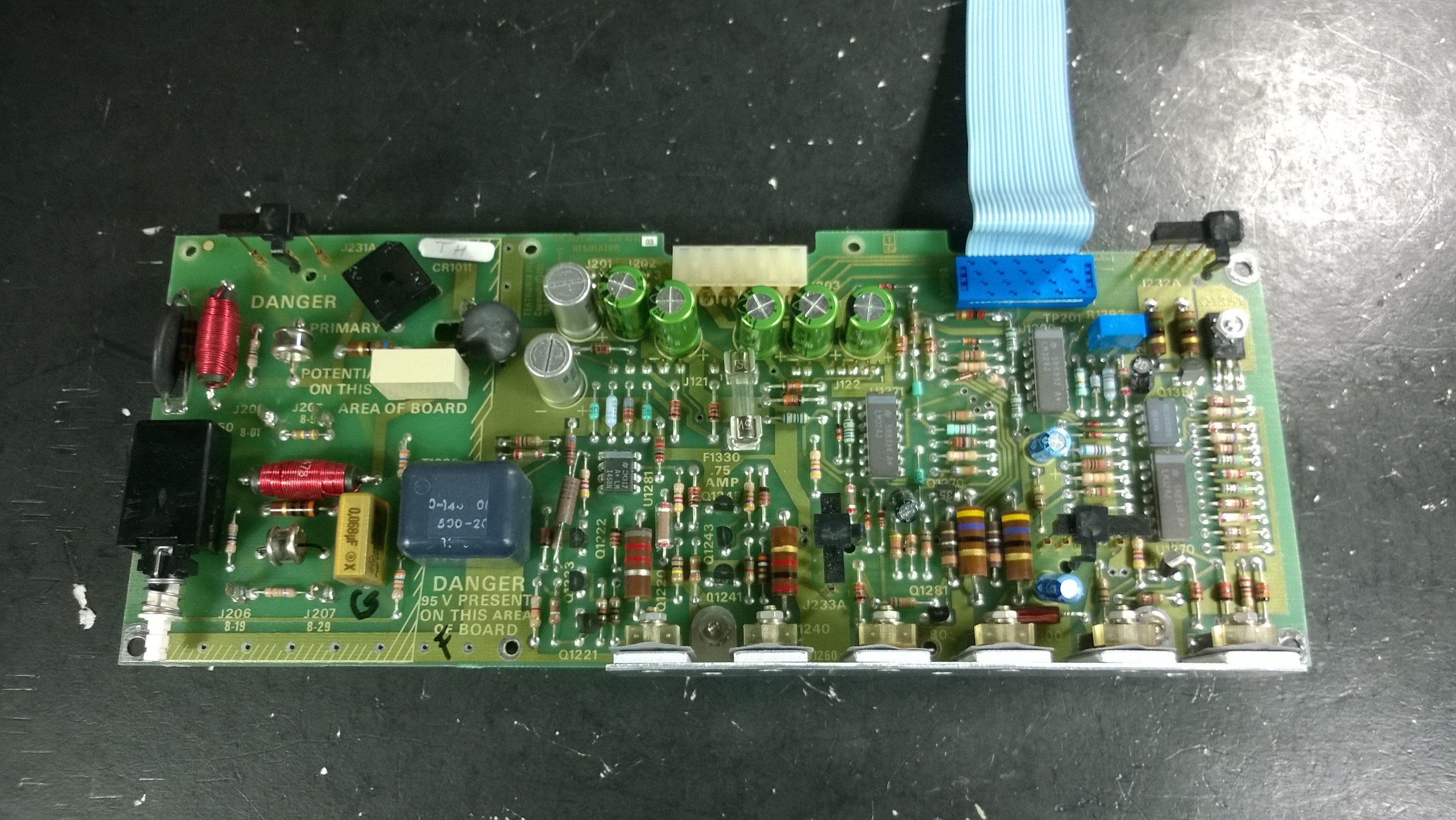
2465B A2 Board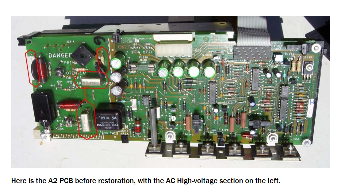
2465 A3 Board
2465B A3 Board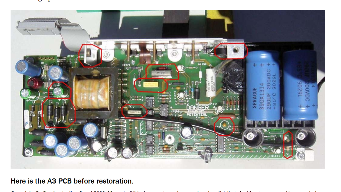
-
I have a 2465B that I've come to (lovingly?) address as a red headed child. All voltages present at the test point and in spec, ripple is in spec, Nothing wrong with it except that it has no cal data (new chip) and won't boot. Anybody have any ideas here?
Thanks in advance. -
I have a 2465B that I've come to (lovingly?) address as a red headed child. All voltages present at the test point and in spec, ripple is in spec, Nothing wrong with it except that it has no cal data (new chip) and won't boot. Anybody have any ideas here?
What's the history with this unit? Did it work and now it doesn't or did you receive it broken?
Are there any LEDs lit on the front panel? Does it go through part of the boot sequence and get stuck? Are any relays clicking as it boots? Any flashes of anything on the CRT? Or does it just sit there like a lump? Need more info.
One thing you could do is try working through the troubleshooting flowcharts in the back of the service manual (immediately after the schematics). They don't cover every possibility, but can at least lead you to the right area to start digging.
-
I have a 2465B that I've come to (lovingly?) address as a red headed child. All voltages present at the test point and in spec, ripple is in spec, Nothing wrong with it except that it has no cal data (new chip) and won't boot. Anybody have any ideas here?
What's the history with this unit? Did it work and now it doesn't or did you receive it broken?
Are there any LEDs lit on the front panel? Does it go through part of the boot sequence and get stuck? Are any relays clicking as it boots? Any flashes of anything on the CRT? Or does it just sit there like a lump? Need more info.
One thing you could do is try working through the troubleshooting flowcharts in the back of the service manual (immediately after the schematics). They don't cover every possibility, but can at least lead you to the right area to start digging.
Worked when I got it, then i tried restoring it.
Right now, what it does when powered on is exactly this;
Brief flash on the CRT, fan comes on, seemingly all front panel LEDS light, then it just sits there like a lump. Doing nothing except running the fan and staring at me with a brightly lit front panel.
Completely unresponsive beyond this and it will sit there for half an hour at least without change, does this every single time I try turning it on. -
...
What "restoring" things did you do? Maybe posting decent resolution photos of those areas you worked on would allow someone to spot something.
Worked when I got it, then i tried restoring it.
Right now, what it does when powered on is exactly this;
Brief flash on the CRT, fan comes on, seemingly all front panel LEDS light, then it just sits there like a lump. Doing nothing except running the fan and staring at me with a brightly lit front panel.
Completely unresponsive beyond this and it will sit there for half an hour at least without change, does this every single time I try turning it on.
One of the first things the CPU does is take control of the front panel LEDs. So, it's not even getting off the ground. Very few components need to be working for this initial phase. Not even the SRAM is needed.
I would focus on the CPU and EPROM functions. Make sure nRESET is going high and that the CPU has a working clock and supply. Make sure J503 NORM/DIAG jumper is in the NORM position.
Have you tried the troubleshooting flowchart? It will take you through all these checks, plus if the NOP diagnostic loop on the CPU should be run. -
What "restoring" things did you do? Maybe posting decent resolution photos of those areas you worked on would allow someone to spot something.
New capacitors, a new fan and a new chip. I tried to transfer the cal data to the new chip but, like an idiot, botched it.
One of the first things the CPU does is take control of the front panel LEDs. So, it's not even getting off the ground. Very few components need to be working for this initial phase. Not even the SRAM is needed.
I would focus on the CPU and EPROM functions. Make sure nRESET is going high and that the CPU has a working clock and supply. Make sure J503 NORM/DIAG jumper is in the NORM position.
Have you tried the troubleshooting flowchart? It will take you through all these checks, plus if the NOP diagnostic loop on the CPU should be run. -
Check all connectors properly mated, recapping.....note error on schematic or layout on PSU 2 lytics interchanged.
Jon -
I bought this programmer:
http://www.ebay.com/itm/321085130796
it arrived safely and quickly.
for the chip, this is the one I ordered but it seems to be out of stock right now:
DS1225AD-200IND+-ND
AD is a wider temperate range (I think) but nothing critical to the scope. the 200 is the speed of the device and I used the same speed as the original chip. not sure if going faster or slower would matter but I just matched the same chip speed.
mouser has one that is not AD but very close and that's probably also ok:
DS1225AB-200+
Maybe some one can answer this for me and others, maybe it has already been done.
Can we use the:
DS1225AD-70+ chip here? is 70ns vs 200ns.
-
...
Maybe some one can answer this for me and others, maybe it has already been done.
Can we use the:
DS1225AD-70+ chip here? is 70ns vs 200ns.
The 70ns version should be fine. -
Looking at this parts list, I find myself questioning the the changes in voltage or capacitance.
For example let's take the filtering capacitors hanging off the output of the inverter transformer, C1110, C1111, C1113, C1114, C1115, and C1116. The originals are a blend of 180 and 250 uF. 330 seems like a bit of a jump, moving the poles of the LC filters the form from 2.2 kHz and 1.9kHz to 1.6kHz. That, I'm less worried about, since I don't see knocking an extra few dB off the ~41Khz switching noise as a particularly bad thing, and I don't think the increase in charging current from the increase in capacitance would load down the inverter too much more. However, is there not a consideration on undercharging electrolytic capacitors shortening their life? Per the voltages in the diagram, the stock 180uF caps on the +/- 15V lines, at 19.2V at this point in the circuit are being charge up to about 48% of their max voltage, and the 250uF caps on the unregulated +/- 5V lines (at 7.1V) are being charged up to about 35%. However, with the 50V rating on the proposed parts list, those unregulated lines are only being charged up to 14% of their rating. Is this too low of a charge for a healthy cap life?
I'm not saying these are unreasonable choices, given the choice of the Panasonic EB series. Looking on the datasheet, 330uF was the smallest value that wasn't lower than the original value 250uF caps. However, 220 uF is available to replace the 180 uF 40V, and a 220uF 50V is cheaper than 330uf 50V. Was this part selection driven somewhat by a desire to keep the parts list small and simple?
A 330uf will work fine in place of the 250uf cap.
If you look at the BOM in the service manual, the 250uf cap have a tolerance of +100% and -10%. Clearly, it's better to go up in value. Since 100% would be 500uf, a 330uf will be no problem.
Other caps listed have +50% and similar rating. Check out the parts list.
-
all this makes me glad I have held off for so long with (3) 2465/7B units PSU recaps...
-
This is my first post and am a newbie.
I am waiting for my 2465B to show up. Everything is like new, the only thing is the scale illumination is not working. Is it worth replacing? I looked in the service manual and there are not pics to help me replace it.
Should I replace the board or just leave it?
If I should replace it and pics or video that show how to do it? I searched YouTube and everywhere and can't find anything
Thanks in advance for the help!
Bill