I'm doing some tests and i have some trouble with the uA range.
I set up a basic led circuit and measured the current on the mA range and the probe inserted into the A/500mA socket, the led is powered on and i measured 9mA.
I switched the range into the uA range and the probe into the mA/uA socket but the led does not power on and nothing is measured on the meter. I checked the 400mA fuse and there is no continuity... fuse blown?? I think that this range should measure 9mA..
The maximum allowed in the uA position is 500uA so should indicate OFL. It takes a second to show. Fuse should have continuity. Does probe in mA/uA socket, switch in ma work?
Finding the maximum range for each position is a little problematic. The chart on page 16 of manual is useful if available. The auto range position doesn't indicate the max just the current auto range.
So you have to:
1. With probes not hooked up but inserted into desired sockets (required for current)
2. Rotate switch as desired.
3. Select mode.
4. Press range and note the max range value in the lower right corner of display. Continue pressing range until you find the max.
I don't think this is much different than other meters but the text for the value is so miniature I can't even see it without my glasses. On other meters it is much more prominent.
Thanks for your help.
no, with the probe in mA/uA socket and the switch in mA range is not working. for sure the fuse is blown. i'm looking for a replacement.
thanks for all the tips!
Backer 795 in Sweden just received SENDUNGSBENACHRICHTIGUNG from DHL.
Delivered to my door a couple of minutes ago.
Only one serial number on the back. The shiny eevblog serial sticker is missing. Was this sticker only on the first batch or did mine skip this manufacturing step?
I'm doing some tests and i have some trouble with the uA range.
I set up a basic led circuit and measured the current on the mA range and the probe inserted into the A/500mA socket, the led is powered on and i measured 9mA.
I switched the range into the uA range and the probe into the mA/uA socket but the led does not power on and nothing is measured on the meter. I checked the 400mA fuse and there is no continuity... fuse blown?? I think that this range should measure 9mA..
The maximum allowed in the uA position is 500uA so should indicate OFL. It takes a second to show. Fuse should have continuity. Does probe in mA/uA socket, switch in ma work?
Finding the maximum range for each position is a little problematic. The chart on page 16 of manual is useful if available. The auto range position doesn't indicate the max just the current auto range.
So you have to:
1. With probes not hooked up but inserted into desired sockets (required for current)
2. Rotate switch as desired.
3. Select mode.
4. Press range and note the max range value in the lower right corner of display. Continue pressing range until you find the max.
I don't think this is much different than other meters but the text for the value is so miniature I can't even see it without my glasses. On other meters it is much more prominent.
Thanks for your help.
no, with the probe in mA/uA socket and the switch in mA range is not working. for sure the fuse is blown. i'm looking for a replacement.
thanks for all the tips!
could this be a valid replacement? because I can't find any fuse at 400mA 1000VDC..
https://www.tme.eu/it/details/zgssh-0.4a/fusibili-63x32mm-super-veloci/siba/701254004/

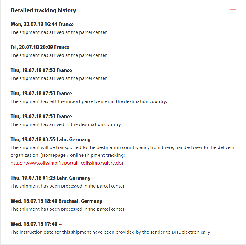
That's moved more than mine

Was there any status update for you? Mine is the same. I don't why it takes so long for German post to process parcels. In the mean time I have ordered and received parcels from UK, Italy and France...
Alexander.
My meter finally arrived today and although I have yet to use it in a real situation here are a couple of observations/thoughts about the meter and android app (I don't have any Apple devices so can't say if they are the same or not):
1. The blue tooth and 1Khz filter are below their respective buttons whereas everything else is above, until I read the manual I thought that they were controlled by the buttons below them not above.
2. When connected by blue tooth to the app and you cycle through the "setup" menu you get the setup values showing on the secondary display of the phone - is it possible to put a bit more detail on the phone screen e.g. "Year 2018" instead of "18", "Buzzer Off" instead of "0v" etc.
3. With the meter in setup mode "b-OFF", "Meter ID" and Logging Interval it shows it as a voltage in the app.
4. With the meter in setup mode month and day "07-23" it shows it as 1815 in the app
5. With the meter in setup mode hour and minutes "18-00" it shows it as 4412 in the app
6. In the user manual section "Setup Menu" on page 57 you are missing the "Buzzer On/Off" which should be between "Auto Power Off" and "LCD Contrast"
7. In the buzzer option of the setup menu maybe change it to say "buz.on" and "buz.of" instead of "b-on" and "b-off" - it might be a clearer what the menu item is then without having to consult the manual.
I know that some of these may not be easy or possible to change but thought that you might appreciate some more feedback.
Wow its far more compact than I was imagining and may well end up joining my everyday carry in the tool box.
Now I just need to find the time to use it on a project (I have several in mind if i get the chance).
Jem
Edit: added point 7
My meter finally arrived today and although I have yet to use it in a real situation here are a couple of observations/thoughts about the meter and android app (I don't have any Apple devices so can't say if they are the same or not):
1. The blue tooth and 1Khz filter are below their respective buttons whereas everything else is above, until I read the manual I thought that they were controlled by the buttons below them not above. We might be able to fix that, would take a while though.
2. When connected by blue tooth to the app and you cycle through the "setup" menu you get the setup values showing on the secondary display of the phone - is it possible to put a bit more detail on the phone screen e.g. "Year 2018" instead of "18", "Buzzer Off" instead of "0v" etc.
3. With the meter in setup mode "b-OFF", "Meter ID" and Logging Interval it shows it as a voltage in the app.
4. With the meter in setup mode month and day "07-23" it shows it as 1815 in the app
5. With the meter in setup mode hour and minutes "18-00" it shows it as 4412 in the app
6. In the user manual section "Setup Menu" on page 57 you are missing the "Buzzer On/Off" which should be between "Auto Power Off" and "LCD Contrast"
7. In the buzzer option of the setup menu maybe change it to say "buz.on" and "buz.of" instead of "b-on" and "b-off" - it might be a clearer what the menu item is then without having to consult the manual.
I know that some of these may not be easy or possible to change but thought that you might appreciate some more feedback.
Wow its far more compact than I was imagining and may well end up joining my everyday carry in the tool box.
Now I just need to find the time to use it on a project (I have several in mind if i get the chance).
Jem
Edit: added point 7
1. Yeah, that has caught out a few people, but once you know its all fine, I think its the light icon that throws people off as its the only one below the buttons.
2 - 6. The App doesn't yet have any reason to support the setup menu (the app cannot interact with the setup menu, it cannot press setup), but it might eventually make it in an update but it doesn't have any pressing need.
7. Z doesn't display particularly well on a 7 segment display, see screenshot
Happily received the unit and am testing the bluetooth connectivity for temperature readings
Have searched the forum for the possibility to change the reporting rate of the external temperature probe - any clues if that can be adapted to like reading every 50 ms ?
Thanks, Gernot
adapted to like reading every 50 ms ?
But can a temp probe be so fast? I thought they have some (thermal) inertia...
Backer #746, got mine today.

When logging AC Volts and secondary display is frequency what is the frequency accuracy? The display shows xx.xx but the log file shows xx.xxx which is contradictory and implies different accuracies.
Here is a log of the line voltage and frequency during our current heat spell in California. Is the frequency data meaningful?
So with the meter now available in the store, is it safe to assume that all the Kickstarter units have shipped?
If so, I'm backer 2059 and have yet to receive a shipping notification.
Just received mine!
Alexander.
When in AC+DC mode the meter only display the sum? Can I select seeing the dc/ac component on the secondary display?
Alexander.
adapted to like reading every 50 ms ?
But can a temp probe be so fast? I thought they have some (thermal) inertia...
Thats a good point - anyway is there a way to change the reading interval ?
adapted to like reading every 50 ms ?
But can a temp probe be so fast? I thought they have some (thermal) inertia...
Thats a good point - anyway is there a way to change the reading interval ?
A thermocouple has
very low mass, and therefore reacts extremely fast.. probably even faster than 50 ms.
The problem here, is that the 121GW (or any other handheld DMM) has a fastests sample rate of 200ms, or 5 Sa. /sec, as specified for DC V, afaik.
Other ranges like 50M Ohm are even slower.
Anyhow, for a faster response, you'll need a bench DMM, which provides NPLC 1sampling, for example.
Frank
A thermocouple has very low mass, and therefore reacts extremely fast.. probably even faster than 50 ms.
Okay, let's put it this way: is measured object changes temperature that frequently? I'm just asking. This depends on what to measure, but for me 50ms interval doesn't look like really necessary in most situations.
The problem here, is that the 121GW (or any other handheld DMM) has a fastests sample rate of 200ms, or 5 Sa. /sec, as specified for DC V, afaik.
There might be faster update rates at reduced resolution. That was one of the reasons I tried to roll out my own firmware: let user trade accuracy for update speed. But I miserably failed, stm32 is not my thing.
Hi,
I investigated on the obvious threshold of the 50 Ohm and 500 Ohm ranges.
It was strange, that in both ranges 0.000 Ohm were displayed, even when the input was shorted by a cable, which should give a few 10 mOhms.
So I measured a resistor box with short cables on my 3458A, and then applied the same configuration to the 121GW:
Setting 3458A 121GW
0.0 0.02743 0.000
0.1 0.12948 0.079
0.2 0.22764 0.178
...
50.0 50.03912 50.005
Especially at 0.1 Ohm setting, and also with rising settings of 0.2, 0.3, 0.4, you can directly see, that my 121GW had a constant threshold of 0.050 Ohm. (gain error does not apply at low values)
At 50.039 Ohm, the gain error of the 121GW additionally chimes in, virtually reducing that threshold value.
This threshold originates from the zero calibration process. UEI probably does not use a direct, low Ohm shunt, but instead uses a cable and a calibrator, set to zero Ohm, which in sum have these 50mOhm, which are always subtracted from the raw Ohm reading.
If a lower resistance short is applied, this would give a negative reading, so the instruments sets all negative readings to zero (threshold).
What confuses much more, that this threshold also shows up using REL.
If you try to zero the value at 0.1 Ohm setting, you will get a 0.050 reading when setting the decade to 0.2.
That's obviously an error in the firmware:
I suppose, that the REL value is taken from the raw reading, then subtracted subsequently from the raw reading first, and then the calibrated zero value is subtracted additionally, which should not happen.
So I made a re-calibration of the 50 Ohm and 500 Ohm ranges only, using a short of < 1.5mOhm for zero calibration, and reference resistors, including cables with 49.971 Ohm and 499.990 Ohm, as measured again with my 3458A, and good enough for calibration.
Now, this threshold is not visible anymore, and you can also make reasonable REL measurements on the mOhm scale, because these 1.5mOhm do no longer play a role.
Frank
PS: Before this investigation, I stored the original calibration values on the SD card, and during that process recalled these from the SD card several time, that's been very practical.
Anyhow,the cal.bin file, also contains some SETUP parameters like APO, BUZZER, LCD, as these were also restored to their original values.
Received mine and followed the gospel to take it apart first...
Seems like hand soldering is challenging because 4 failure points (1 unsoldered joint, 1 disturbed joint and 2 joints without enough solder).
Others have probably posted the J1 and J2 look like my attachment.
Din;t take apart mine yet.
One thing I don;t like is that it doesn't default to the main function of the knob position. It remember the last mode it was.
What about the AC+DC mode? Can it use the second display to show the components?
Alexander.
One thing I don;t like is that it doesn't default to the main function of the knob position. It remember the last mode it was.
That is a very nice feature.
Looks like The 121 GW just officially sold out on the store.
There was something Like 80 units available 40 mins after the message from Dave was sent at 9:39 pm US eastern time Yesterday.
Can’t wait!