-
That will be great to have. Seemed a difficult/impossible task until all the proper items are in hand to complete that cal...
-
Could someone please explain how one does put the values gathered with the EXER 02 routine into a BIN file?
I downloaded a file that is from a B055xxx serial number scope that is very close to mine. I wanted to replace the cal constant values to match the ones gathered from my own scope into this file at the corresponding locations. For one just to learn how to do it, and possibly to also have a backup file ready if the reading of my NVRAM should go wrong for some reason. There was a brief explanation of the value writing procedure into the file that I read somewhere else some time ago, but I didn't really understand the procedure as the explanation sounded overly simplistic, probably meant for someone that had a much better general understanding. My new replacement DS1225-AD-150 from Mouser is already in the mail, but I still need to order a programmer, and of course pull the NVRAM from the scope and install a socket.
Basically each value read with the Ex02 goes as "00 00C7", "01 26B7", and so on all the way up to "FF 0000 X". Some values also have this "X" appended, and I understand the X is just to indicate even parity. I have a Hex editor program installed and have done some very basic editing in the past (edit maybe 1 or 2 values at a very specific and clearly spelled out location), but I'm lost with the cal data. How do I write the individual values into the BIN file that has a line format like shown bellow, and what part of the data corresponds to what position in this layout?
Offset (h) 00 01 02 03 04 05 06 07 08 09 0A 0B 0C 0D 0E 0F
00000000 18 3E 60 B1 60 B1 60 B2 60 B2 7D 16 7D 17 7D 17
00000010 7D 17 13 .... and so on.
BTW found this at the TekIO group, but again the technical information is a bit too advanced for me.
https://groups.io/g/TekScopes/topic/7656133#120148
Any explanations, pointers, or even links to other already existing clear explanations for a newbie in this procedure will be much appreciated.
-
Could someone please explain how one does put the values gathered with the EXER 02 routine into a BIN file?
Here, try this explanation...
...
Any explanations, pointers, or even links to other already existing clear explanations for a newbie in this procedure will be much appreciated.
Each of the 256 values shown in EXER 02 is placed into two consecutive bytes in the DS1225, and in the order shown in EXER 02 since the 6800 processor in these scopes is big-endian (most significant byte first). Assume the EXER 02 data is all cal data and important, since there is no map of the locations and what they actually do.
The EXER 02 data is stored at the end of the DS1225 starting at location 0x1E00 and ending at 0x1FFF (that's a total of 512 bytes for all 256 values).
The remainder of the DS1225 (0x0000 - 0x1DFF) does not need to be initialized to any particular value that I'm aware, but you could put all 0x00 or all 0xFF in there for good measure.
For for example, suppose your EXER 02 data looks like this:
00 1122
01 3344
02 5566
03 7788
04 99AA
...etc...
FE BBCC
FF 0000
You would use your hex editor to enter these values into the DS1225:
1E00 11 22 33 44 55 66 77 88 99 AA
...etc...
1FFC BB CC 00 00
The parity, "X", doesn't matter in this procedure.
If you're starting with someone else's contents, it should be 8192 bytes long. You can replace the values at 0x1E00 to 0x1FFF with your EXER 02 values. -
MarkL
Hi thanks for the explanation so far. So the address you indicate as "1E00" (only 4 digits) which I understand would be the first line to start entering the values, would be equivalent to what I see in my Hex editor as "00001E00" ? (8 digits).
Also on my editor I see 16 offset columns for each address row (00, 01, 02, 03 ... to 0F - see my attached image), whereas your example does only show 10 offset columns for each address row. Is there maybe a setting I need to modify in my editor so things will look like the example you are presenting? I am using HxD Editor v1.7.7.0.
Thanks again, much appreciated for taking the time to explain this.
-
MarkL:
OK I started trying some things on the Hex Editor program and found that by changing the bytes per row from 16 to 10 (DOH) it will give me the correct row length that matches your example. I still get the four zeros in front of the 4 digit address, I assume this the usual way to look at the addresses and just ignore the leading zeros?
Could you please check the updated attached image and let me know if this would be correct in accordance to your example from your post above?
Thanks again.
-
MarkL:
Yes, you are right that the leading zeros don't matter.
OK I started trying some things on the Hex Editor program and found that by changing the bytes per row from 16 to 10 (DOH) it will give me the correct row length that matches your example. I still get the four zeros in front of the 4 digit address, I assume this the usual way to look at the addresses and just ignore the leading zeros?
Could you please check the updated attached image and let me know if this would be correct in accordance to your example from your post above?
Thanks again.
The selection of 10 or 16 also doesn't matter in that field. Although I don't have that hex editor, it looks like it's just controlling the number of bytes displayed on each line. I only provided 10 values in the example starting at 0x1E00, but it could have been 16. There's no significance in the data to the number of bytes displayed on each line. Sorry if that led to confusion.
So, what you've typed in so far is consistent with the example data I gave. Just keep going until you've entered all 256 of your EXER 02 values (not the example data I showed). The last byte you enter should be at 0x1FFF.
If this is still not clear, I've attached a 8192 byte template that might help. Starting at location 0x1E00, the bytes in the template appear like this (and everything else is 0x00):
0001e00: 00 00 00 01 00 02 00 03 00 04 00 05 00 06 00 07 ................
0001e10: 00 08 00 09 00 0a 00 0b 00 0c 00 0d 00 0e 00 0f ................
0001e20: 00 10 00 11 00 12 00 13 00 14 00 15 00 16 00 17 ................
0001e30: 00 18 00 19 00 1a 00 1b 00 1c 00 1d 00 1e 00 1f ................
...
0001fe0: 00 f0 00 f1 00 f2 00 f3 00 f4 00 f5 00 f6 00 f7 ................
0001ff0: 00 f8 00 f9 00 fa 00 fb 00 fc 00 fd 00 fe 00 ff ................
Replace each pair of bytes with the corresponding data from your EXER 02. In other words, "00 00" gets replaced with the data from EXER 02 location 00. "00 01" gets replaced with the data from EXER 02 location 01. "00 02" with the data from EXER 02 location 02. And so on, all the way to EXER 02 location FF which replaces the pair "00 FF".
EDIT: Fixed typo.
-
MarK, thanks very much for the template and additional clarification. I will work on rewriting my own Exer02 data into it. That was very helpful. Maybe I could even post my finished BIN file and if someone out here in the US with a programmer would be willing to write the data for me into a fresh DS1225AD-150 and mail it to me to FL zip 33152, I would be more than willing to pay for the efforts and cost of shipping. That way once I pull my original NVRAM and install a socket I could compare them and verify that it actually works to copy the exer02 values into a chip and put to rest that this might not be feasible as some members of the TekIO group stated in older messages I found. Or maybe in the end they will be proven right, but at least we will know.
One last question if you don't mind, when you refer to a line by labeling it as "0x1E00", what is the meaning of the "x" in it? Is this a common convention just to save not having to write it with all the leading zeros as in 00001E00, or does it have another meaning?
Thanks again.
-
One last question if you don't mind, when you refer to a line by labeling it as "0x1E00", what is the meaning of the "x" in it? Is this a common convention just to save not having to write it with all the leading zeros as in 00001E00, or does it have another meaning?
In C and similar computer languages, 0x indicates a number specified in hexadecimal notation. Frequently, but not strictly, the number of digits implies the number of bits, e.g. 0x0001 is stored in 16-bits whereas 0x01 is stored in 8-bits. Hence if you had a 32-bit address space the lowest address would be 0x00000000 and the highest 0xffffffff. -
Mark: I typed in all the Exer02 values into your template and it fit exactly within the expected address range, so i guess all is well. The changed fields are in red. Took about 25 minutes, not too bad, just don't distract me while I'm typing.
What i will do next is save the file and reopen it so it will all be shown again in black, and make a second data input pass, so if I made any mistakes earlier, they would be shown in red and easy to see.
-
As requested here is an alternate procedure for calibrating the Counter/Trigger option. First, here is the copy of the cal procedure from the 2465 Options Service Manual. I assume the procedure is the same or similar for the 2465A/B.
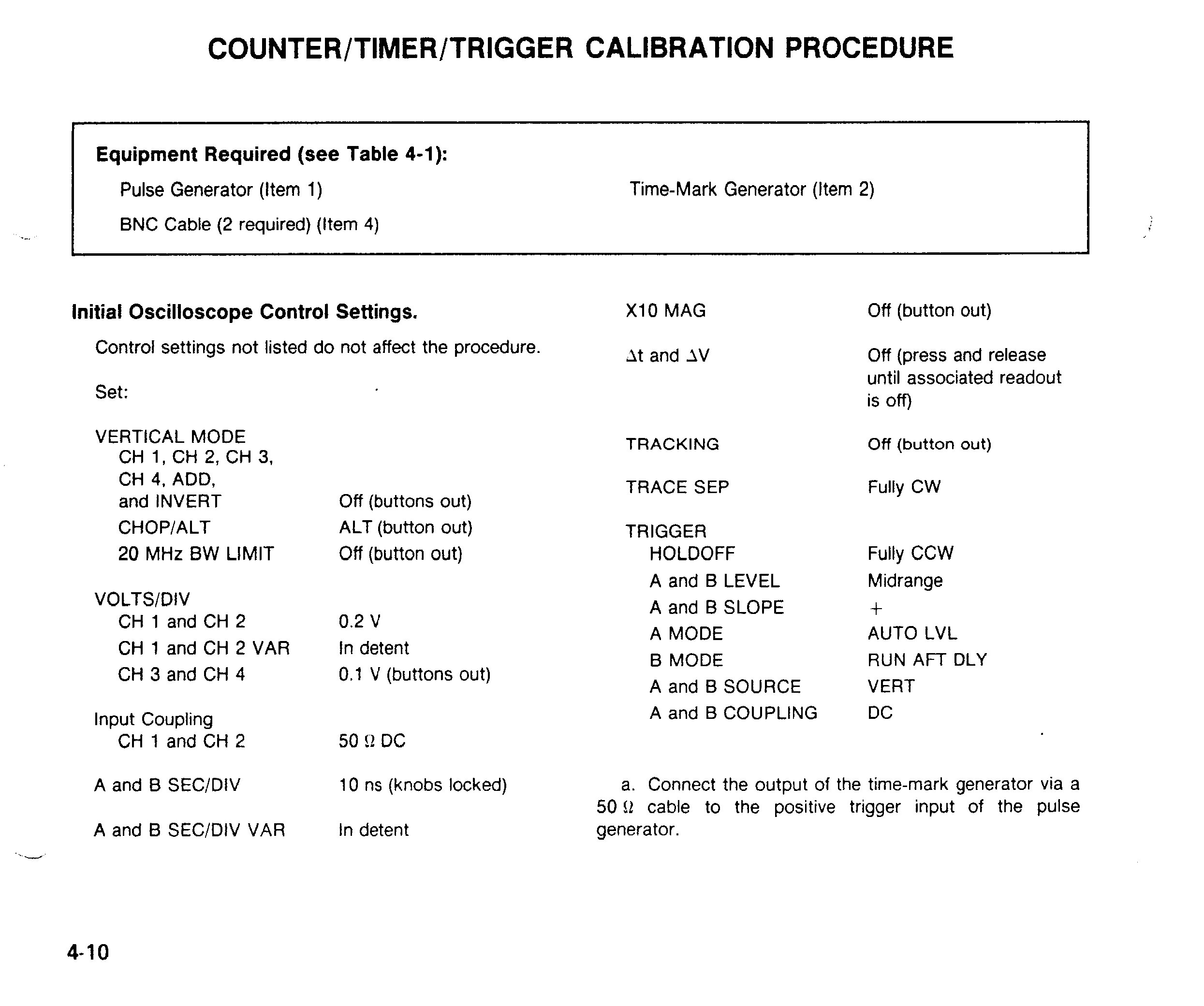
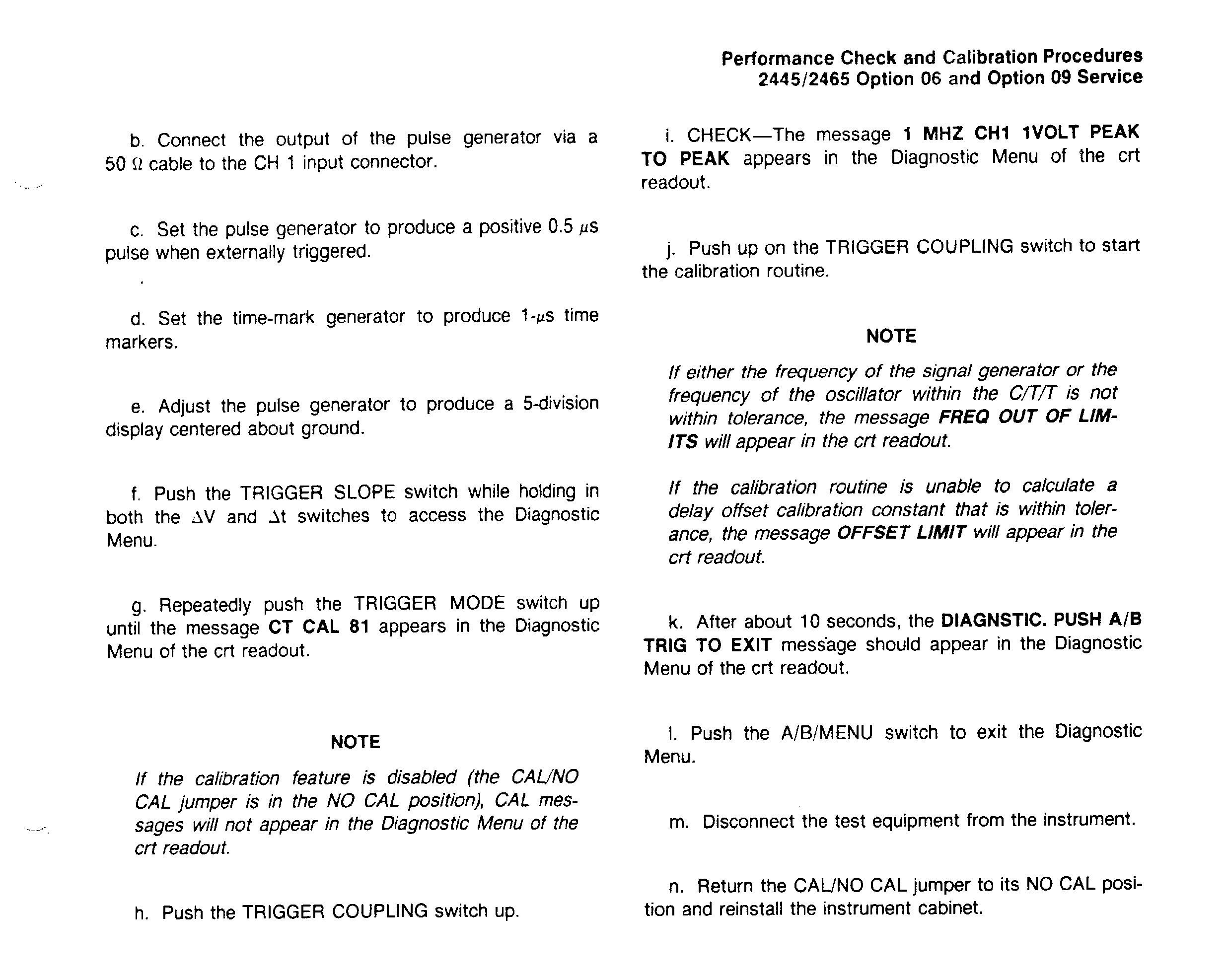
The alternate procedure was from a gray beard on the Yahoo Tek Group who's name I forget and I take no credit for developing this procedure. But I can tell you from experience that it does work. You can use a function generator, oscilloscope calibrator, or home made pulser with the following requirements:
Square wave must be exactly 1 MHz.
Rise time of 1ns or less.
0.8 to 1 volt peak to peak.
Preferably as close to 50% duty cycle as possible but not absolutely necessary.
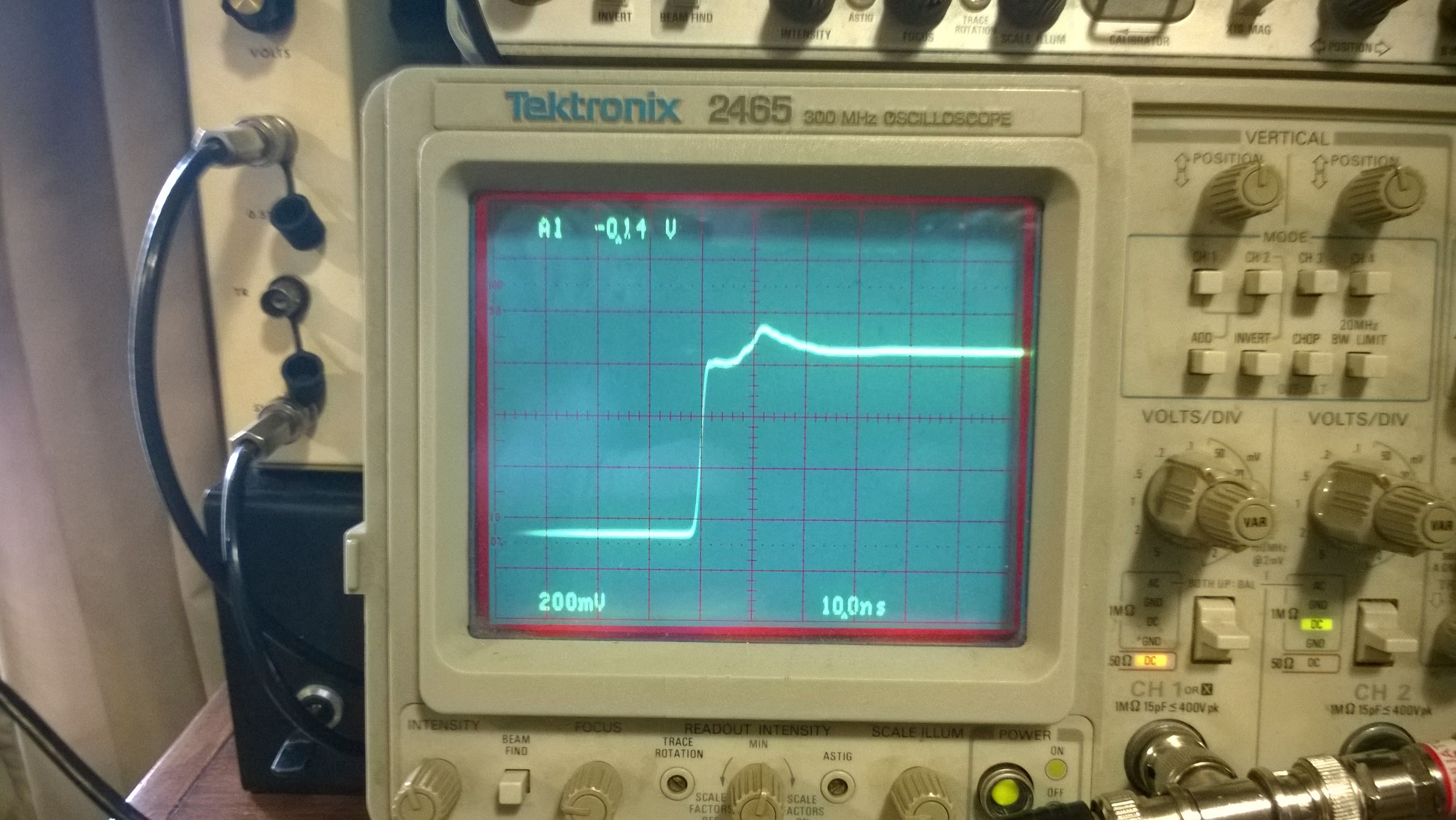
Must not have an either positive or negative offset. In other words, must be equally above and below 0 (GND) centerline. See first trace example. I have a Heath IG-4244 Oscilloscope Calibrator which meets all the requirements except it has a fixed negative offset as shown. If your signal source has an adjustable offset set it for approx .4V to .5V p-p above and below centerline (.8V to 1 V p-p total). Then set up your scope as per the cal instructions and proceed right to step F and do the cal. As long as your source is exactly 1 MHz it should work. If you have an offset issue see next step.
Negative offset: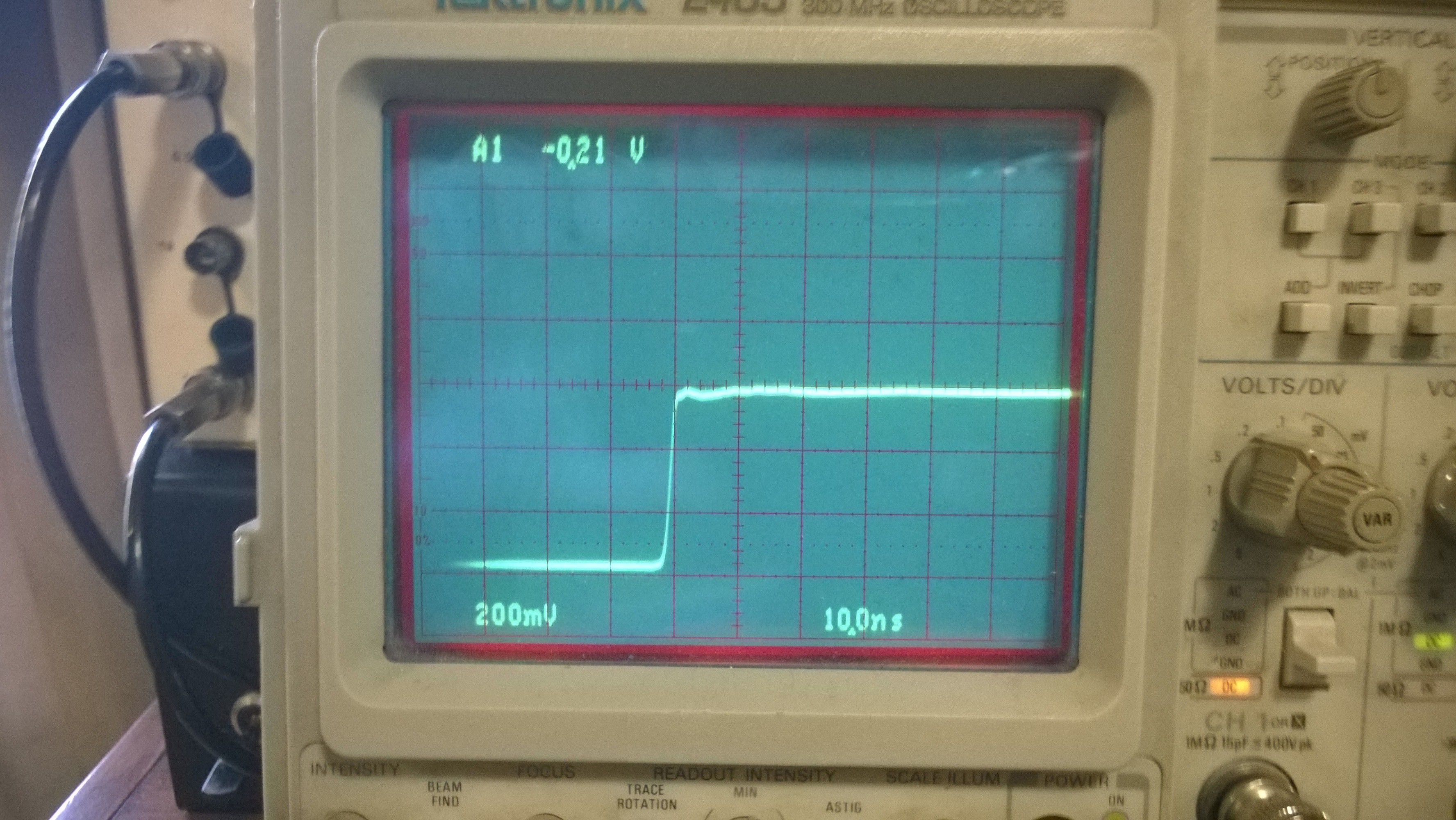
What you'll need:
BNC “T” connector.
6dB inline attenuator.
DC supply that goes down to 0 volts.
50 ohm coax.
Connect the signal source to the left. Connect the power supply to the attenuator. If your source is a negative offset connect positive to center pin. If the source is a positive offset connect negative to the center pin. Slowly increase the voltage until you obtain a waveform similar to the 2nd pix. .8 volt - 1 volt p-p equal to centerline. Then proceed to step F and do the cal. It should take. If not go back and check your setup.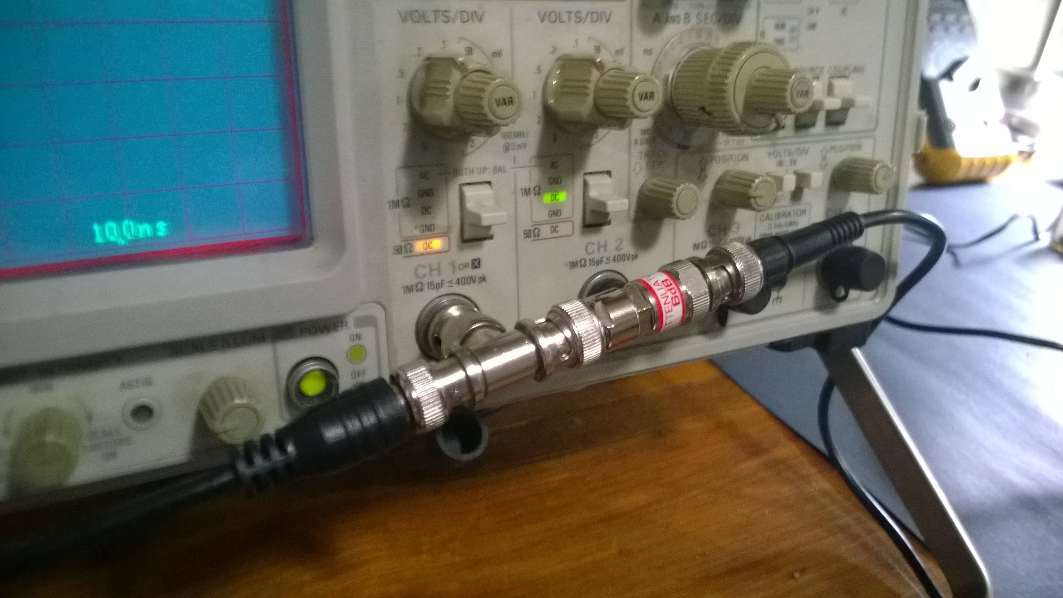
-
MarK, thanks very much for the template and additional clarification. I will work on rewriting my own Exer02 data into it. That was very helpful. Maybe I could even post my finished BIN file and if someone out here in the US with a programmer would be willing to write the data for me into a fresh DS1225AD-150 and mail it to me to FL zip 33152, I would be more than willing to pay for the efforts and cost of shipping. That way once I pull my original NVRAM and install a socket I could compare them and verify that it actually works to copy the exer02 values into a chip and put to rest that this might not be feasible as some members of the TekIO group stated in older messages I found. Or maybe in the end they will be proven right, but at least we will know.
Glad it worked out for you!
...
If your goal is to prove that writing the EXER 02 values into the NVRAM works, that's already been verified.
There have been multiple conversations about it on TekScopes groups.io. Which one are you referring to? The last one I recall was the thread "tektronics 2465b 400mhz nvram battery info" where someone verified it with a 2467B in April.
Although I didn't mention it in a post a couple of weeks ago (reply #1182), I also verified that both the EXER 02 and the GPIB dump of the cal data was an exact copy of what's in the NVRAM on a 2445A. But I didn't bother mentioning it because it had been done before.
It's also been verified on a 2465, although that scope is a little different since it doesn't use a Dallas NVRAM.
So, we have all the versions covered for this series (A, B, and plain).
More verification is always nice, but it may not be worth the extra hassle if you don't already have a programmer or other equipment to do it.
That being said and you still want to experiment, I'm willing to drop your BIN data in a fresh DS1225AD-150 for you for free, if you want to send me the chip and a self-addressed, pre-paid return envelope. PM me if you want to set this up.
-
My Tek 2445B developed an interesting belly dance at first power up when cold. I think it is the capacitors on the main board. What do you masters think? It stabilises after 2 - 3 minutes and it is stable after that.
I tried to remove two of the knobs from the front panel and both broke, that's how brittle they are. Without removing those knobs there's no way to get to the main board. Anyone has a set of brightness, focus, etc knobs? -
Dirty H Position pot ?
An analog meter would probably be the best thing to clearly show it with tests.
You also might be able to confirm it in X-T mode. -
My Tek 2445B developed an interesting belly dance at first power up when cold. I think it is the capacitors on the main board. What do you masters think? It stabilises after 2 - 3 minutes and it is stable after that.
I tried to remove two of the knobs from the front panel and both broke, that's how brittle they are. Without removing those knobs there's no way to get to the main board. Anyone has a set of brightness, focus, etc knobs?
Agree with tautech. Try cleaning the horizontal position pot.
Knobs....mnementh had a spare focus knob for my 2465. He may have some additional. PM him and make sure you tell him I sent you.
If he doesn't, Google is your friend. There are multiple sites selling Tek parts. I'm sure you can find them. -
As requested here is an alternate procedure for calibrating the Counter/Trigger option. First, here is the copy of the cal procedure from the 2465 Options Service Manual. I assume the procedure is the same or similar for the 2465A/B.
The alternate procedure was from a gray beard on the Yahoo Tek Group who's name I forget and I take no credit for developing this procedure. But I can tell you from experience that it does work. You can use a function generator, oscilloscope calibrator, or home made pulser with the following requirements:
Square wave must be exactly 1 MHz.
Rise time of 1ns or less.
0.8 to 1 volt peak to peak.
Preferably as close to 50% duty cycle as possible but not absolutely necessary.
Must not have an either positive or negative offset. In other words, must be equally above and below 0 (GND) centerline. See first trace example. I have a Heath IG-4244 Oscilloscope Calibrator which meets all the requirements except it has a fixed negative offset as shown. If your signal source has an adjustable offset set it for approx .4V to .5V p-p above and below centerline (.8V to 1 V p-p total). Then set up your scope as per the cal instructions and proceed right to step F and do the cal. As long as your source is exactly 1 MHz it should work. If you have an offset issue see next step.
Negative offset:
What you'll need:
BNC “T” connector.
6dB inline attenuator.
DC supply that goes down to 0 volts.
50 ohm coax.
Connect the signal source to the left. Connect the power supply to the attenuator. If your source is a negative offset connect positive to center pin. If the source is a positive offset connect negative to the center pin. Slowly increase the voltage until you obtain a waveform similar to the 2nd pix. .8 volt - 1 volt p-p equal to centerline. Then proceed to step F and do the cal. It should take. If not go back and check your setup.
Thanks for posting this; it may come in very handy
-
My Tek 2445B developed an interesting belly dance at first power up when cold. I think it is the capacitors on the main board. What do you masters think? It stabilises after 2 - 3 minutes and it is stable after that.
I tried to remove two of the knobs from the front panel and both broke, that's how brittle they are. Without removing those knobs there's no way to get to the main board. Anyone has a set of brightness, focus, etc knobs?
Agree with tautech. Try cleaning the horizontal position pot.
Knobs....mnementh had a spare focus knob for my 2465. He may have some additional. PM him and make sure you tell him I sent you.
If he doesn't, Google is your friend. There are multiple sites selling Tek parts. I'm sure you can find them.
In X-Y mode shown in the video, CH1 vertical position acts as horizontal. In Y-T though, the readout is affected as well and readout is independent of any pots. Maybe the picture below will clarify some things...
-
Next step then is to monitor the supply voltages at J119 on the main board and see if one of them is bouncing around. And with that many hours have the Inverter and Regulator boards ever been recapped? If not I highly recommend it be done.
-
Next step then is to monitor the supply voltages at J119 on the main board and see if one of them is bouncing around. And with that many hours have the Inverter and Regulator boards ever been recapped? If not I highly recommend it be done.
I recapped the power supply few years ago with good Nichicon PW series caps. -
Maybe the picture below will clarify some things...
Wow, 41K plus hours of operation? Have you owned the scope since new or for a long time? Looks like during its life it might not have been officially recalibrated either, at least not at an accredited lab. The tech that performs the cal is supposed to also reset this counter after each calibration, so the next tech guy that has to deal with the instrument will know the elapsed time. But if just left to run it also can give a ballpark idea of the usage, but then again, it may have more than 41K hours on the clock, with one or more resets along the way. -
Next step then is to monitor the supply voltages at J119 on the main board and see if one of them is bouncing around. And with that many hours have the Inverter and Regulator boards ever been recapped? If not I highly recommend it be done.
I recapped the power supply few years ago with good Nichicon PW series caps.
OK, but I would still monitor the PSU voltages at initial power up and see if something is amiss. Rule that out first before digging into it further.
-
Glad it worked out for you!
If your goal is to prove that writing the EXER 02 values into the NVRAM works, that's already been verified.
There have been multiple conversations about it on TekScopes groups.io. Which one are you referring to? The last one I recall was the thread "tektronics 2465b 400mhz nvram battery info" where someone verified it with a 2467B in April.
Although I didn't mention it in a post a couple of weeks ago (reply #1182), I also verified that both the EXER 02 and the GPIB dump of the cal data was an exact copy of what's in the NVRAM on a 2445A. But I didn't bother mentioning it because it had been done before.
It's also been verified on a 2465, although that scope is a little different since it doesn't use a Dallas NVRAM.
So, we have all the versions covered for this series (A, B, and plain).
More verification is always nice, but it may not be worth the extra hassle if you don't already have a programmer or other equipment to do it.
That being said and you still want to experiment, I'm willing to drop your BIN data in a fresh DS1225AD-150 for you for free, if you want to send me the chip and a self-addressed, pre-paid return envelope. PM me if you want to set this up.
I was not sure yet that it had been verified. It seems to be a touchy subject for some members over at TekIO when asked, as can be seen on some past messages. In a situation where a scope lost the calibration constants, some of them will tell you to rather invest the time in getting the scope properly calibrated than to thinker trying to rebuild the cal data with exer02 values, as it might not work, or at best be no longer accurate and on the dot anyhow. I get their point, but then again, my scope is intended for hobby use only, not on a bench at NASA. Also, I can understand the interest in using Exer02 data in a situation where someone lost the cal data, and has no intentions to send the scope out for calibration, or does not have the means to calibrate it himself. 10x better, maybe even 100x better to have your own Exer02 data to play with than having to use a third party bin file from another scope just to bring yours back to life.
I did not see the message thread over there that you mentioned. Will look it up later.
In my case I am just trying to do it mostly as an academic exercise, and of course to possibly avoid having to read my aging NVRAM to replicated the data as a first choice. As it has happened before to some people, the programmer itself might kill the data while trying to access it if the backup battery is on its very last legs. Yes, I've also seen the PDF about repowering the internal battery, and its of course yet another option to go.
Thanks for the offer to program a DS1225 for me and mail it back, I will keep it in mind. Thing is I don't have a programmer, and this would probably the only instance I would ever use it, so trying to decide if I should order one. I have read the GQ-4X4 programmer is probably the one to get, as it will handle both the DS1225, and also the FRAMs in case I decide to thinker with them in the future and get rid of the battery backup issue for good. Or if anyone can suggest a better alternative programmer I'll be happy to listen to recommendations.
Yesterday went again over my handwritten list of the Exer02 values and checked them against the video which I also made. Turns out that in one data pair I transposed two numbers (I had written 2647 and should have been 2674). Other than that I'm good to go, and I updated your BIN template file as well.
-
I tried to remove two of the knobs from the front panel and both broke, that's how brittle they are. Without removing those knobs there's no way to get to the main board. Anyone has a set of brightness, focus, etc knobs?
I read somewhere that carefully warming up the knobs with a heat gun really helps to remove the stuck ones (after so long most of them will be) without breaking them. I have not tried this yet, and hope for now I will not need to. Knock-knock... -
Maybe the picture below will clarify some things...
Wow, 41K plus hours of operation? Have you owned the scope since new or for a long time? Looks like during its life it might not have been officially recalibrated either, at least not at an accredited lab. The tech that performs the cal is supposed to also reset this counter after each calibration, so the next tech guy that has to deal with the instrument will know the elapsed time. But if just left to run it also can give a ballpark idea of the usage, but then again, it may have more than 41K hours on the clock, with one or more resets along the way.
No, I only have it since about 2012 when was decommissioned at work due to the trace waving like a flag in the wind. It was not worth fixing it and I got it for free. I recapped the power supply right away and the waving went away but considering it had bone dry capacitors in the PS, I don't think those on the main board are in much better shape.
The instrument was calibrated yearly by an accredited lab up until, I would guess, 2008 - 2009. It was probably left running 24/7/365 as I know the place.
Are you sure that counter is resettable? It is the ON counter and probably it is stored in the same infamous NVRAM that I replaced this summer. -
Are you sure that counter is resettable? It is the ON counter and probably it is stored in the same infamous NVRAM that I replaced this summer.
The explanation about the counter was given to me to a very knowledgeable TekIO group member that I understand keeps himself busy by providing calibration services for all variants of the 2465 scope and selling them as well. He routinely zeroes those counters. I don't know myself how to do this, but I'm sure its described somewhere in the calibration instructions of the service manual.
As he put it: "The power cycle counter, and on time counter are meant to be reset after every calibration. They are there to let the technician know how long it has really been since the last calibration... as opposed to whatever the customer says.. They don't mean much to a customer. If you see really low numbers, it simply means the scope saw little use since its last calibration." -
Next step then is to monitor the supply voltages at J119 on the main board and see if one of them is bouncing around. And with that many hours have the Inverter and Regulator boards ever been recapped? If not I highly recommend it be done.
I recapped the power supply few years ago with good Nichicon PW series caps.
OK, but I would still monitor the PSU voltages at initial power up and see if something is amiss. Rule that out first before digging into it further.
I remember doing that some time ago, I will try that again before ordering the caps... which probably is necessary.
Thanks!