Great! And nope, I'm the Markus who does the m-firmware. The Markus who did the original design abandoned the project. Karl-Keinz (k-firmware) took over and I joined in.
Do you have any documentation on your version of the firmware? Is it an enhanced K firmware or something alltogether different?
The distribution package includes a readme file describing all the differences. The functionality of both firmwares is quite similar. but there are differences on how things are done. And the m-firmware lacks support of graphical LCDs (might change). The m-firmware measures caps down to 5pF for example, or is able to distinguish MT1 and MT2 of a detected TRIAC.
And the m-firmware lacks support of graphical LCDs (might change). The m-firmware measures caps down to 5pF for example, or is able to distinguish MT1 and MT2 of a detected TRIAC.
Well, if you find yourself with a little time on your hands, how about adding the graphics support (with pretty device pictures), the ability to measure FET on resistance, and a scope/logic analyzer mode? I'd buy you a beer...
Great! And nope, I'm the Markus who does the m-firmware. The Markus who did the original design abandoned the project. Karl-Keinz (k-firmware) took over and I joined in.
Do you have any documentation on your version of the firmware? Is it an enhanced K firmware or something alltogether different?
The distribution package includes a readme file describing all the differences. The functionality of both firmwares is quite similar. but there are differences on how things are done. And the m-firmware lacks support of graphical LCDs (might change). The m-firmware measures caps down to 5pF for example, or is able to distinguish MT1 and MT2 of a detected TRIAC.
I'm going to give your firmware a try, mind posting a link to the distribution package? The sites I've found are all in German.
I've tried 1.17m
It seems somewhat different, it seems to be in continuous auto test mode and it doesn't begin a calibrate when I connect all three leads on power up. Also I haven't found any other test modes (holding down the switch on the k firmware). Does it need the rotary switch?
I've tried 1.17m
It seems somewhat different, it seems to be in continuous auto test mode and it doesn't begin a calibrate when I connect all three leads on power up. Also I haven't found any other test modes (holding down the switch on the k firmware). Does it need the rotary switch?
Please read the README file in the distribution archive. Everything is explained there. Power on the tester with a long key press (>0.3s) for the auto-hold mode. For the menu short circuit all three probes or press the test button two times (short key presses). And it doesn't require a rotary encoder, besides for the squarewave generator.
Hello
I bought on ebay this esr meter
everything is working ok except for the measurement of capacity and ESR
If I measuring small value capacitors <10uF readings are quite accurate but when I measure 100uF results are about 200uF (5 capatitors new and used) esr 0.20-0.40ohm
for 1000uF readings are 600-700uF,
470uF readings 0nF vloss around 1% esr no readings
1500, 2200uF readings 0nF
for all test I used brand new and used capatitators
Can someone help me to fix it? I try calibrate (connect pins 1 2 3 go trough test mode....)
thank you
Most probably is the wrong setting of fuses. The correct values should be:
lfuse:0xff hfuse:0xd9 efuse:0x04In the annex is backup original firmware of my tester (v2.1) and compiled firmware v1.12k revision 424 (Karl-Heinz Kübbeler).
Note
The problem could be a bad value C16. The correct value must be 1nF.
Yes. I use exactly this type of USBasp programmers. In practice, you can use any ISP programmer intended for programming AVR MCU's.
The attached picture documents connection USBasp to board of my tester with the ISP connector.
I got one of these for $15 off Ebay. So far it's been doing the right thing on any component I tried. I am actually kind of impressed.
How about a link to the seller's page.
"
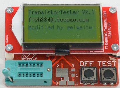
Fish8840 Tester" version I preferred due to the easy implementation of other types of LCD (characters or graphics). Supplementing of few parts (LCD & ISP connector, trimer 10k) and changing one resistor on mainboard LCD (LED resistor) can be used classic 16x2 character LCD. Further adjustments can be with supplemented precision voltage source (R19, U3) and fix the connection of the voltage divider (R8, R15) for battery voltage measurement. A lot of useful information can be found in the
official manual (by Karl-Heinz Kübbeler).
My tester I bought here:
Ebay item: 281477820303
It is precisely this:
Review: Component Tester Fish8840
Note:
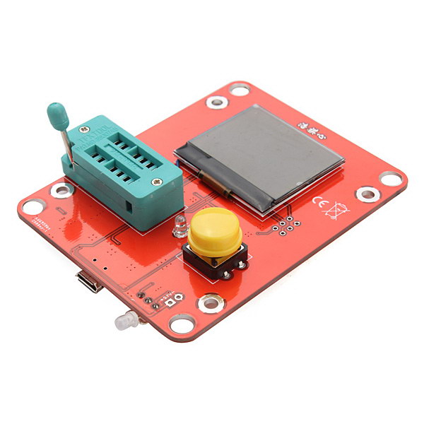
These devices are sold by many vendors with different display panel. However, the motherboard is identical - see attached pictures.
I'm pretty sure all of those originated from Fish8840's TaoBao store.
The yellow "T-4" transistor tester Muxr linked to comes from 91Make's TaoBao, which is also the source of the inexpensive AD584 voltage reference boards, and the slightly more expensive plexi-encased versions that have been mentioned elsewhere on the forum before.
I like the presentation of the information on the 91Make version the best, but I like the
"EZM Electronics Studio" GM328 most because it is, as I understand it, closest to the original design, and open source firmware, plus the MCU is socketed and most of the components are through-hole for easier modification. There are variants with both a graphical display and a 2-line display.
I should probably finish the video I started editing comparing the three...but I probably won't.
I've owned two of these testers now. The first was a Fish8840, which I stupidly killed with a (not very) charged capacitor. My current one is a "Yellow T-4", I got the up-market one with the plexiglass case, but the board looks identical to the cheap ones. I could never think of an easy way of casing the Fish8840 due to the separate display board needing either a stepped front panel or extending the ZIF socket and buttons.
A couple of observations. I agree that the Yellow "T-4" screen layout does seem to be the easiest to read (aging eyes) it also has an external 2.5V reference on board, even if it is only a TL431 rather than anything more exotic, I couldn't find one on the Fish8840 PCB. The battery voltage reading on the T-4 seems to start low on the "T-4" and slowly creep up over subsequent presses of the test button, no idea why that would be. The "T-4" has a slightly amusing representation of a Zener when connected between pins 1 and 3... It shows it as two opposite polarity diodes in SERIES rather than parallel.
The first thing I did after buying the second tester was to fit the relay input protection mod as detailed in the official manual. I hadn't realised just how sensitive the inputs would be to a capacitor that had been unsoldered and sitting for several days (charge recovery).
@Gyro:
I sent a personal message.
I am still waiting for the Free Electron version...
I got this one :
LCR-T5 Mega328 but I am having some issues...
Unit seems to operate well but when testing electrolytic capacitors the screen flickers and gets upside down and mirrored.
Could it be a buggy factory firmware or a component issue? Did anybody else had the same problem?
Are you careful to fully discharge large capacitors before trying to test them?

 This tester includes rechargeable battery - it is only one difference. Images on ebay documented use of the original software by Karl-Heinz Kübbeler. In recent posts on the official discussion forum you will find also some information.