I can read "PWM" and "ESR". The other lines seem to be the same gibberish. That could mean that the items got the same broken pointer. When you enter the PWM tool, do you get a nice list of the frequencies or more gibberish?
When enter the PWM, text display is good, as shown below mr...
Could be some garbage in the EEPROM. I'd try to re-flash the firmware and the eeprom.
After a 62 days wait for delivery, I finally got mine last night. It is a M12864, exactly like this one:
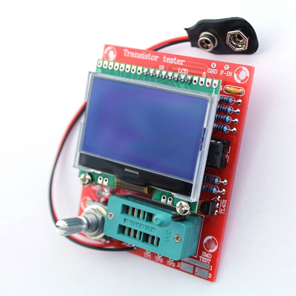
It uses an 8Mhz crystal and all resistors are 1%.
It was assembled and tested and works great! I also dumped the firmware (v1.17) and EEPROM that came with it so I have a copy and can safely play with updates.
Now my questions:
- is my board compatible with the latest firmware (641) on svn? Are there any modifications required?
- if not, what is the latest firmware I can install on my board?
@
AlxDroidDevIt was here several times already mentioned.
Your tester is an identical copy of the original concept and is therefore compatible with the k-version (Karl-Heinz Kübbeler aka kubi48) and m-version (Markus Reschke aka madires) of the software.
Your dump (v1.17

) is probably useless, because the contents of the MCU is standard locked. Basically it does not matter, because the author of this software is Karl-Heinz Kübbeler. Therefore, without any modifications you can be applied directly his original software (directory
mega328_st7565_kit).
However, I recommend carefully studied the official
manual 
 Note
Note:
... It uses an 8Mhz crystal and all resistors are 1%. ...
Interesting, because all kits of this tester, that went through my hands contained the precise (0.1%) value of the test resistors 680 and 470k.
Thank you, @Tom.
Do you think I should set the lock bits after flashing a new firmware ?
You need to set only the standart fuses:
lfuse:0xf7 hfuse:0xd9 efuse:0x04 (0xfc)
I have an older EZM Electronic Studio version bought from eBay a couple of years ago
I have the exact same unit. I've made a few modifications:
- Replaced the 8MHz crystal with a 16MHz one.
- Replaced the test switch with a rotary encoder.
- Added a 1nF capacitor on AREF.
- Put additional 100nF capacitors directly on the socket's Vcc and AVcc pins (just because I have lots lying around).
- Replaced the 10uF/16V electrolytic capacitor C6 with a 22uF/35V tantalum (just because I have lots of them, too).
I try to keep mine up to date with the latest M-firmware.
I used to remove the processor to program it, but then I made a cable for my USBASP programmer, using
IC test clips. With the display removed, I clip them to R4, R5, R6 and R7 for the signals, and on C6 for power.
Markus,
I have the ST7565 kit tester. The rotary encoder is connected to PD1 and PD3. How do I configure this in your software please?
Also, did you write code to support the extra ADC pins of the m328 QFP package? And if not, do you plan to?
Thanks.
@
caiusA rotary encoder is used for easier menu navigation and control functions of the tester. For this DIY KIT of the tester can be used directly to original k-version software without any modifications - either way, this Chinese clone contains exactly this firmware (v1.12k)
@caius
A rotary encoder is used for easier menu navigation and control functions of the tester. For this DIY KIT of the tester can be used directly to original k-version software without any modifications - either way, this Chinese clone contains exactly this firmware (v1.12k)
OK, thanks for explanation.Is v1.12K the latest and best firmware available?Which are issues(I know there are)?
@caius
Currently is it the most appropriate version of software. K-version is under development and testing, but so far everything is working normally. If you know of any bugs, please give some information. I recommend carefully studied the official manual!
@caius
Currently is it the most appropriate version of software. K-version is under development and testing, but so far everything is working normally. If you know of any bugs, please give some information. I recommend carefully studied the official manual!
OK, I'll get the kit and test the assembled unit reporting feedback.Thanks for you help.
@
caiusOff topic:
Please, do not use unnecessarily the button quote

Just use only the reply
I was going to use the reply button but then I thought someone would not have understood mine was a reply to your post
@
caiusOT: If the question or reply is immediately after the post msg, it is not unnecessary to use the quote. Some users have also problem with this

Note:
Button "
Quote" should not be used to the last post - but it would have to set the administrator of this discussion forum.
I have the ST7565 kit tester. The rotary encoder is connected to PD1 and PD3. How do I configure this in your software please?
Everything is in config.h
Enable the rotary encoder option (#define HW_ENCODER), set pulses/detents (#define ENCODER_PULSES 2) and adjust the encoder I/O pins (#define ENCODER_A PD1). And there's a dedicated section for the M12864's display.
Also, did you write code to support the extra ADC pins of the m328 QFP package? And if not, do you plan to?
Not yet, but if an interesting hardware option for one of the extra pins comes up ...
LCR-TC now in color, and shall probably sell for 50usd on ebay. Not an owner yet, I can't show more.
OK, roger
Sorry. I did not intend to touch you somehow
No, you are perfectly right!We have to respect the netiquette all the time.
LCR-TC now in color, and shall probably sell for 50usd on ebay. Not an owner yet, I can't show more.
That modified firmware has nice graphics. Unfortunately the author doesn't provide the source code and ignores that the firmware is open source.

But we have color support too. And I think I'm able to add touch screen support for an ATmega 664/1284 version.
I got mine working with Trendy 1.21m!
I want to thank Markus for the superb job he`s done with the firmware, and specially thank him for supporting all the hardware that others have developed around his initial project. He's done such a great work, I don't even care about losing 7x1 to Germany!
I also want to thank tom666 for the huge amount of help he`s been giving everyone and the time and effort he's put into this forum.
Guys, you are awesome!
Not yet, but if an interesting hardware option for one of the extra pins comes up ...

Oscilloscope input of course.
Sorry. I did not intend to touch you somehow
Tom, this is a poor choice of the word "touch". We understand what you mean, but in another situation, it might sound criminal.
Use instead: I did not intent to piss you off/irritate you.