-
Buyers beware, misleading 34470A reference modules (clones) on eBay.
Posted by TiN on 23 Dec, 2020 05:30 -
All know that I have soft spot for ultra-stable DC Voltage references. When I saw some interesting looking module labelled as Semi-finished 34470A Ultra Precision Voltage Reference Board Without LTZ1000ACH. Note that it does not say "Keysight" anywhere except the PCB, and rightfully so. It's not a Keysight product, but a clone. Perhaps sellers main target audience are hobbyists who interested in upgrading and modifying their 34460A/34461A/34465A 6½-digit DMMs for better temperature stability and lower noise? I was thinking "price looks not too bad, maybe should get one or two to test next year?"
Below screenshot from Dave video, featuring real deal Keysight 34470A teardown and showing voltage reference module construction in great detail.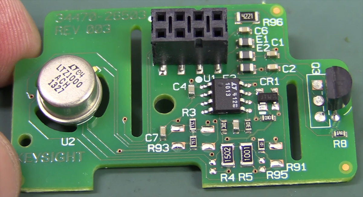
We can see that PCB quality and assembly is impeccable in 34470A with OSP-plated pads and precisely applied solderpaste. While reference circuit design is not very good in 34470A (compared to full potential that LTZ1000A chip is capable of in good hands), it is very good reference totally adequate for 7½-digit DMM. It is essentially replicate somewhat flawed reference circuit design from older legendary HP 3458A, repeating same high oven temperature problem that hurts long-term DCV stability of these instruments. This was deliberate decision to meet +50 °C operating temperature requirements.
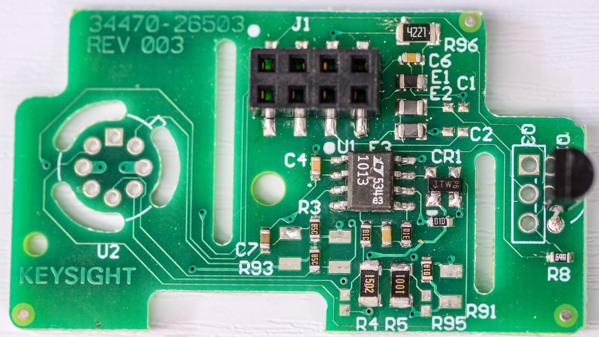
Now is photo from the eBay listing for "34470A reference":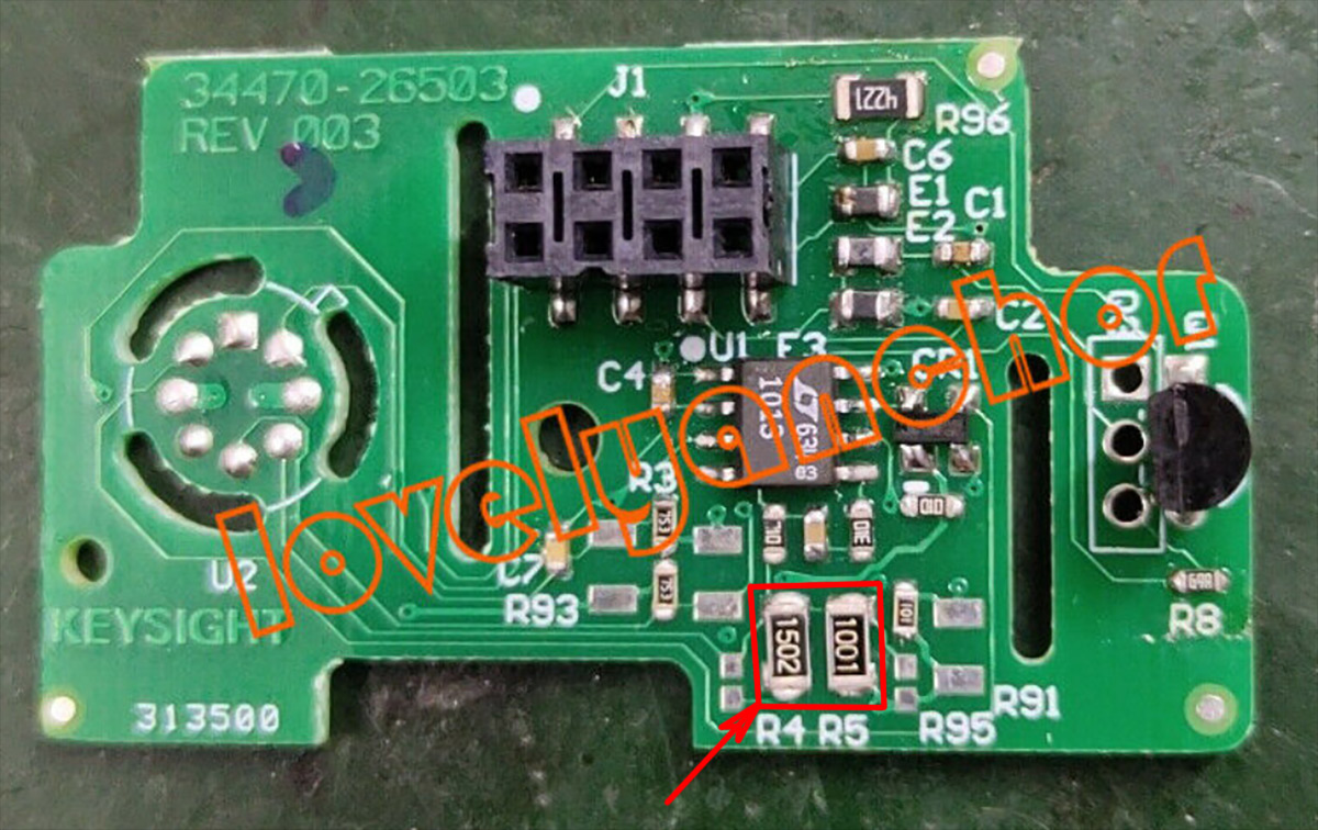
By obvious markers it is indeed very clearly different to original design made by Keysight, and does not look same quality even remotely. But it's not the main issue for me, after all soldering quality is fixable. What matters - it even looked pretty close with same looking 15k and 1k R4 and R5 resistors used for LTZ1000A super-zener temperature setpoint (marked with red square and arrow). Ratio of these two resistors is one of the key performance components that define stability of the LTZ1000A 7V output.
Anyhow, I thought it would be interesting to do some measurements and test these little modules in terms of temperature coeffient stability, noise and long-term drift. Seller accepted $30 USD best offer and two modules were on the way. Too good to be true?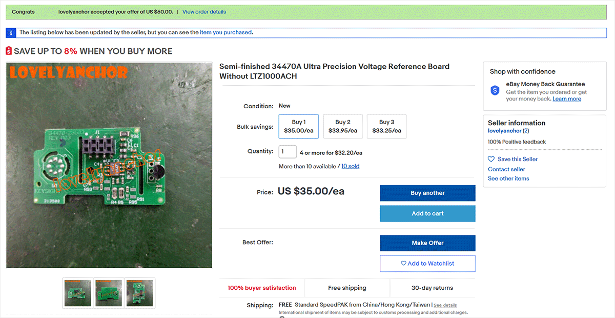
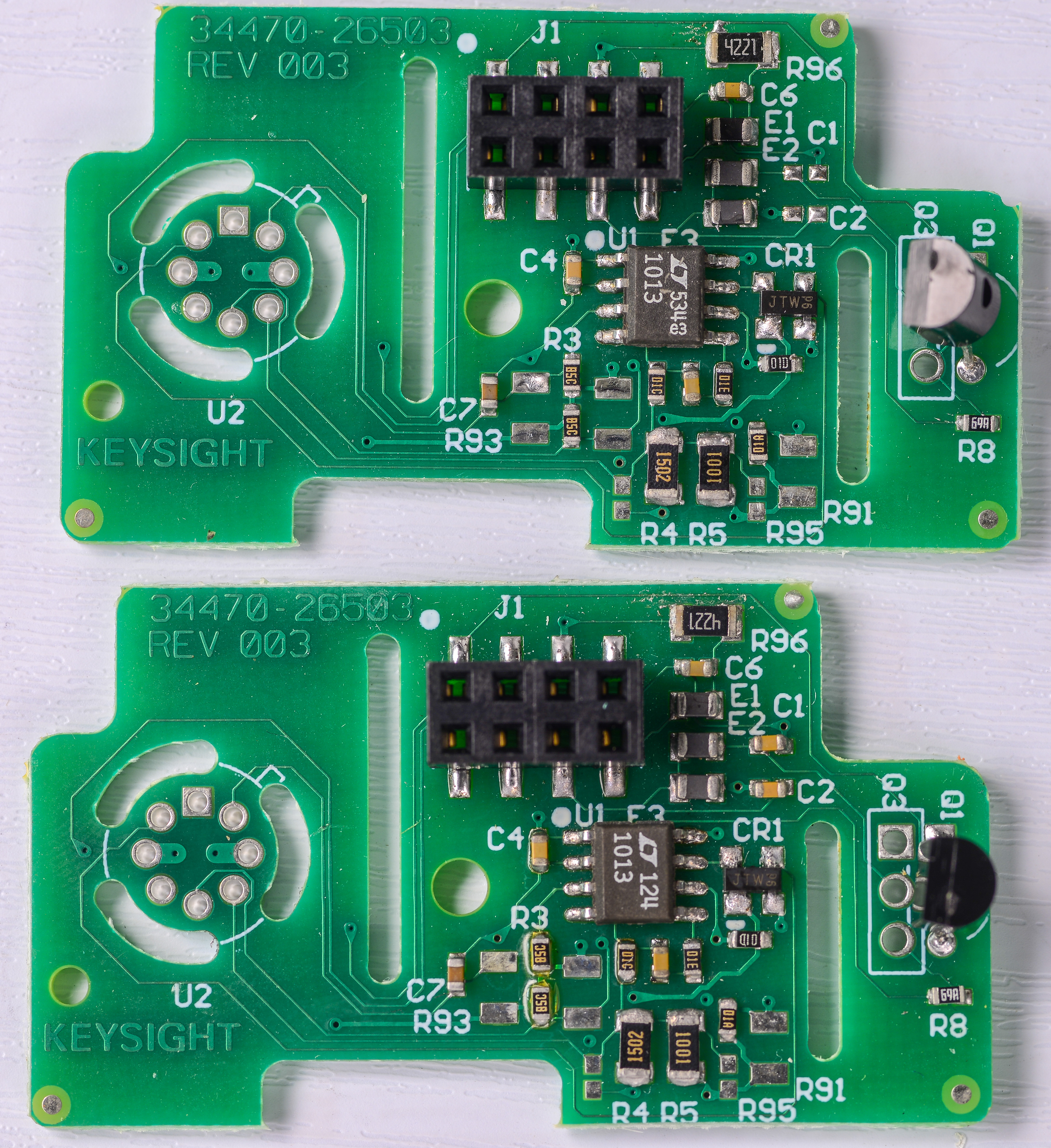
Few weeks later boards arrived, but to my great disappointment PCBs I received are NOT what was shown on the photo in eBay listing

Board assembly quality and overall PCB quality is rather poor, but that does not bother me much. What is a much bigger problem - wrong resistors R4 and R5. Both boards that I received have standard SMD1206 1% resistors and not the special better resistors that are SHOWN ON EBAY listing photo. They may look the same to unexperienced eye, but pay attention on the digits font. Only one manufacturer of SMT resistors using special rounded font shown on both EBAY photo from seller listing and also on real genuine Keysight 34470A from EEVBlog's teardown video.
So this is false advertisement and eBay seller is misleading buyers as he mislead me here.
Also second issue - since I bought two modules, they both have this problems with R4 and R5 resistors, but second module also missing capacitors C1 and C2! Why?
I have messaged seller to either modify listing to reflect correct information, or to refund the order. Will see what happens next.
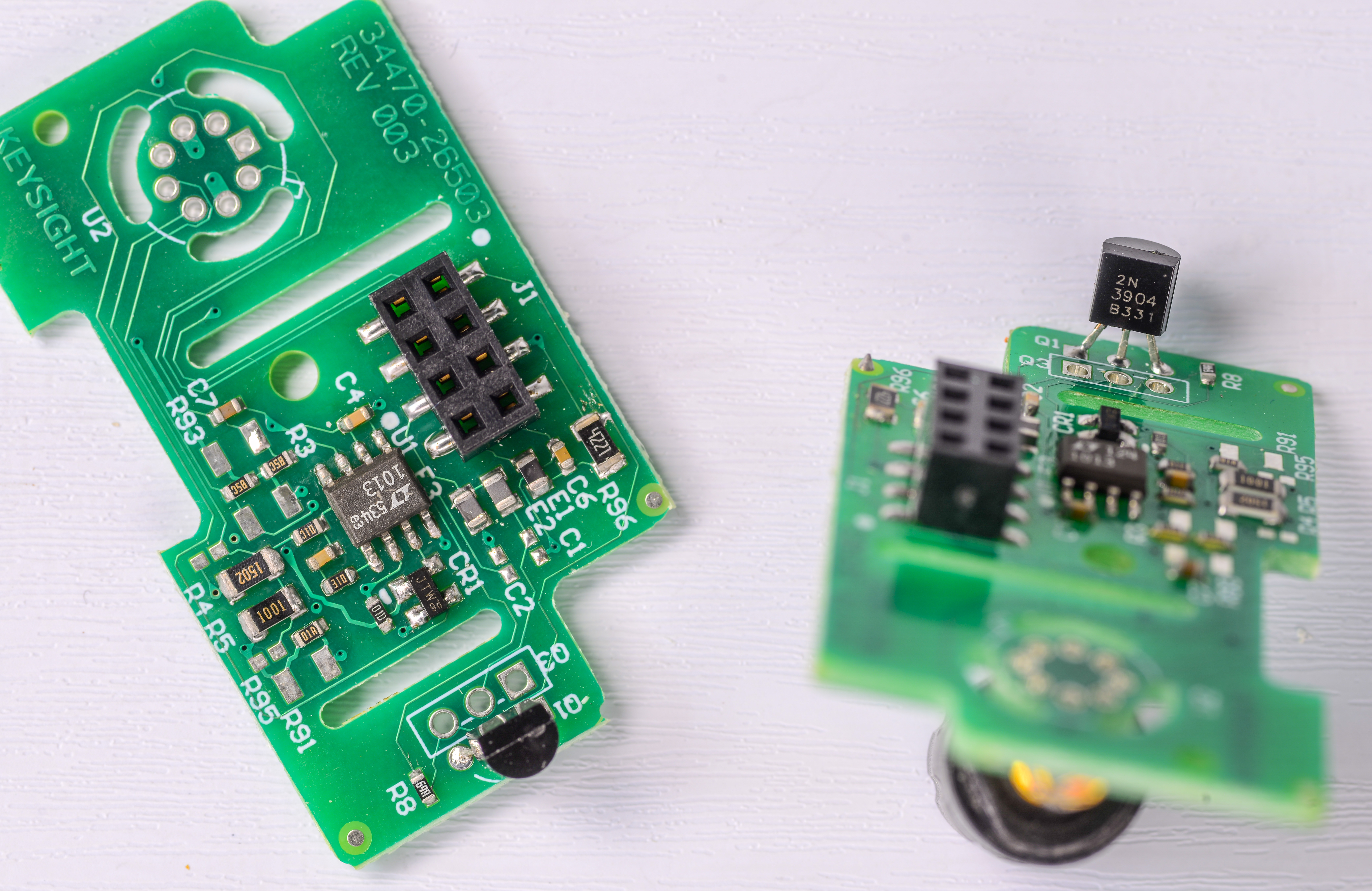
Some more photos. Heater drive transistor is good old 2N3904 in TO-92 package, just like real 34470A ref. No issue here.
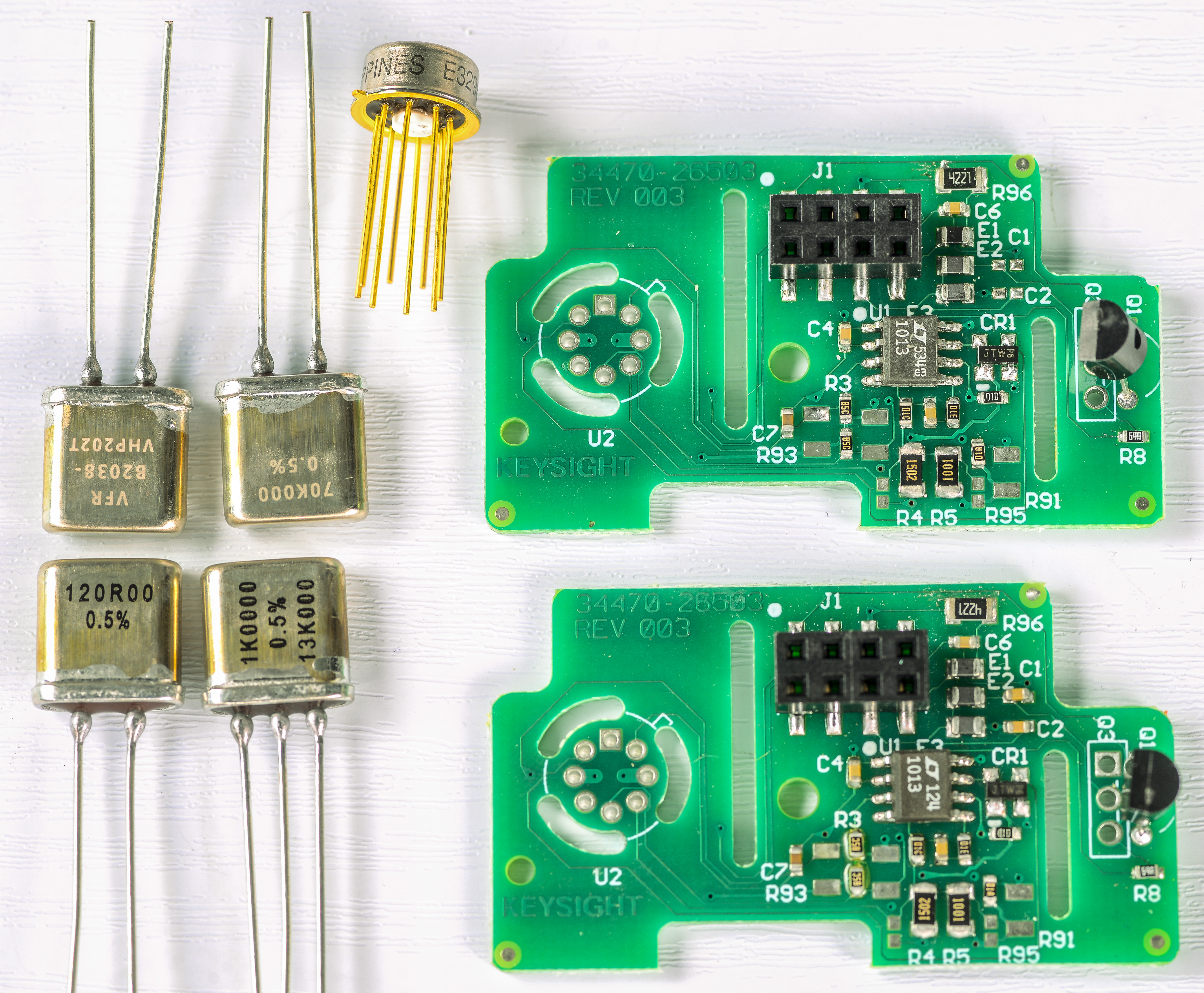
And yes, I know that proper LTZ1000A board components just in resistors would cost 5 times the price of this whole module. Have more than 7 years of experience with various LTZ1000-references and have lot of different designs. It was especially interesting to see how bad is "bad" 34470A reference PCB design is versus expensive typical LTZ1000A with VPG foil resistors and fancy PCBs.
At least 34470A module is smallest there is for production-grade module. It is half the size of old 3458A A9 LTZ1000A module and more than 10 times smaller than my latest quad LTZ1000A ultra-low noise xDevs.com QVR module.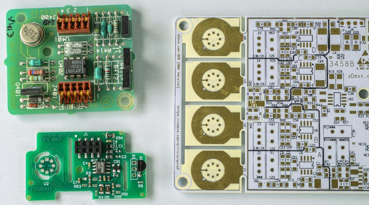
Tests and performance numbers are to be done next year.
UPDATE.
Seller promptly responded and will organize return shipping and replacement to two boards with "proper correct" resistors. I was promised a photo of the new boards before shipping. So hopefully this will be resolved to everybody's satisfaction.
-
It's like a science experiment to see how many people stabbed each other in the back. I'm told that once you get your product made in china, the first thing they do is rip off and distribute all drawings and IP.
I saw a documentary going after methlamine and fentanyl producers in china and the video showed knock-off shops in Shenzen, an entire building full of people hand-painting classic art works.
But here it looks like a port from Mentor to Altium, the silk font reveals that look at the "6". I would wonder if the People's Op-amp LM358 snuck in there.
Check the solder bridge on J1 pin 1-3 at R96.
-
Hi TiN,
I also have seen this PCB, and from the ebay photos it was quite evident that the components were assembled manually.. leadfree soldering by hand is not easy.
So chances were high, that the resistors were also not low T.C. ones.
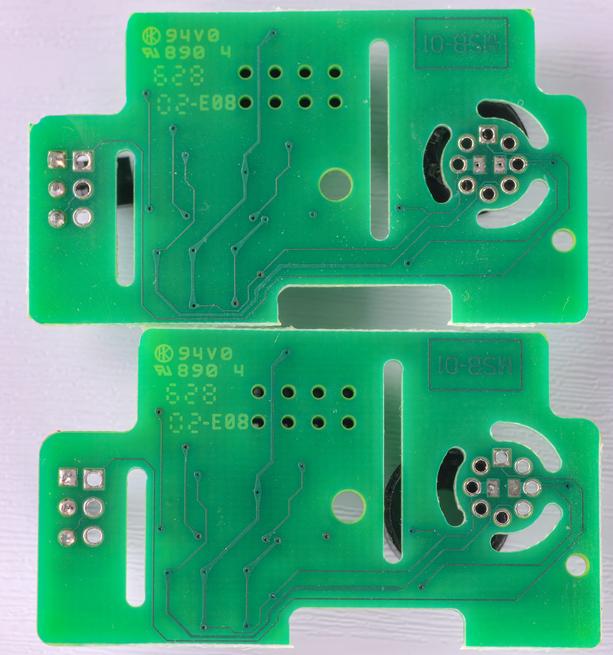
Anyhow I also ordered one, and received it last Monday, see top and bottom shots.
My plan is to fully reverse engineer the PCB, to find out how it's connected to the 34465A/470A, in conjunction with the existing LM399H drive circuit.
There was already a partly deciphered circuit on the forum, but a few tracks were still missing, i.e. these on bottom where a sticker was placed, and a few below the connector and the LT1013.. What I've measures so far, these latter lines make sense. (Kelvin connection )
)
Even if this PCB is a clone, they will probably have copied the circuit correctly, and I have the possibility to compare the bottom side against an original KS board.
The quality of the PCB also does not matter, as Keysight has made the worst design ever, anyhow.. too thin lines, slots, and so on.
TiN, where did you find differences in the layout, already?
My further intention is to replace all 5 precision resistors with small TH metal bulk resistors from AE, the FLCY, which can be squeezed on the existing pads.. and also setting the oven temperature to reasonable 60..65°C (12.5k/1k). T.C. compensation will also be done.
Then I will assemble it into my 34465A so that I can put in the existing LM399H back, if required.
Let's see, if everything works directly, or if this reference would need a SW enabling for the 34470A.. different analogue interface, different ACAL functionality maybe.
Frank
-
I drew this schematic of the board a long time ago, hoping to copy it and make million$... well actually to look at its design.
I could not see underneath the 8-pin header for what pin 2 is about, and if there is a V- rail. I see they can monitor heater output.
Please let me know of any errors/updates and I will update this post.
edit: 2020-12-25 Updated schematic to rev2 based on post #7.
-
Seller replaced photos in his listing, now showing only same crappy film resistors your and mine boards have. Seems like they dont have proper resistors to sell boards with. Was expected something along these lines to happen ($30 shipped, can't expect $45 resistors on the PCB) but still hope dies last.
I might keep one board as received and replace resistors on second to fancy VPG VSMP1206 15k, 1k and 100 ohm to test. Most likely real 34470A module performance would be somewhere in between. That's low priority project for next year/ -
Hello Folks - The seller stated/states from the early beginning that this board is a replica of the Keysight board 34470A-26503 Rev. 003. I bought a few to use it as test fixture to investigate drift problems with the 34470A unit - as I will not probe & solder on the genuine 26503 board. Big question is if they re-used the CAD source files or gerber data files to manufacture this board (1) - or if they handcrafted the artwork - created new CAD database and generated the gerbers themself (2) - the first (1) is form of theft, the latter (2) is an infringement of copyright under US and EU law but probably not in RPC.
It is little bit similar to situation with HP/KS 82357B GPIB adapter - almost perfect clones are available on market for a fraction of cost ... - and I am sure KS Loveland is reading this ...
Anyhow Merry Christmas ...
ScoobyDoo
Herzlichen Grüßen/Meilleures salutations/Best regards/Un saludo -
If one replaces the resistors anyway, why keep it at 15K/1 K and not go for a more moderate 13 K /1 K.
A better grade resistor should be used, but I see no real need to go all the way to foil resistors. Good thin film resistors like the Susumu RG or maybe URG series should be good enough.
I see nothing wrong with a compact LTZ1000 based reference using more moderate grade resistors. However there is no need to do a 1:1 copy of the layout. The main point is getting the kelvin sensing right. The very thin lines look a little odd as they can add to the resistance. However the resistance of the copper traces is reasonable stable over time and the TC contribution should not be too large and can cancel out to some degree. If tested OK, why not.
Anyway, LTZ1000 reference chips are currently hard to get - so it a more theoretical problem. -
Hi,
here are pictures of an original board. (Thanks to somebody from the forum)
I could not find any difference, even the tracks look identical, apart from a single one, which had a slightly different thickness change.
The date code information varies.
Floobydust, there were really several errors in your schematic, like different numbering of the connector, and especially that pin 5 is current feed for GND and REF- and pin3 is REF- sense. pin 4 is n.c., pin 2 is connected to a capacitor.
I'll post the connector later, including LM399 interface.
Frank
I had to get the turkey from the poultry farm, so now I added a sketch of the hidden connections, (by continuity measurements), and how the LM399 and LTZ chip connect to the main board.
I designated the white dot as pin 1 of the connector.
pin3 (Ref- sense) and pin5 (Ref- feed) seem to be connected on the 34465A already .. not sure
pin 4 is definitely n.c., pin 2 I could not yet assign meaningful yet to the circuit.
C1, C2, C6 = 150nF
R3, R93 =75k
R4 = 15k, R5 = 1k
R95 = 100
These resistors should be the high precision ones, which I will replace by TH components FLCY
Thanks in advance for helping.
PS: This turkey will also be calibrated, obviously
-
[...] Floobydust, there were really several errors in your schematic, like different numbering of the connector, and especially that pin 5 is current feed for GND and REF- and pin3 is REF- sense. pin 4 is n.c., pin 2 is connected to a capacitor.
I'll post the connector later, including LM399 interface.
Frank
Thanks, I've updated the schematic to Rev 2 in Reply #3 based on the new info. Please review. Heading out for turkey now.
The original Keysight board might use Susumu precision SMT resistors for the three parts - 15k 1206, 1k 1206, 100R 0603, based on look (RR1632) and the advice of my psychic. But that series is discontinued 2017 and replaced by RG and typically ±5ppm/°C but Digi-Key has some ±2ppm/°C parts unless in error.
Susumu RG3216L-153-L-T05, 15k ±0.01% ±2ppm/°C 1206 (3216 Metric) AEC-Q200 USD $5.20 ea. in 1-lot seems to be the best you can get in SMT. There are 10,000hr graphs for them. I know WW is king.
I would say the original Keysight pc board is sloppy- orphaned extra vias, missing/confusing ref. designators, quirky teardrops, and extra paste on non-populated parts. Usually that stuff gets cleaned up in Design Reviews. -
Hello floobydust,
many thanks for this update!
The schematics now look much nicer.
It all now makes complete sense.. and I now understand how this fits into the usual LM399 drive circuit, probably w/o any SW quirk, .. see schematics of the predecessors 34410A/411A (identical A/D converter Multislope IV, and therefore identical Vref circuit).
Frank -
Hi folks,
I have removed these 5 SMD resistors and made a quick temperature test on the 15k00 one, giving about 25ppm/K only.
Both resistors 1k, 15k, were very close to their nominal values, so I assume these might be 0.1%.
I assembled leaded FLCY resistors instead, and an LTZ1000A, so that all components stood less than 10mm above the top side.
That also allowed me to use a copper plated plier during soldering of the LTZ1000A, to avoid strong heating of the chip, and I really don't like to shorten its legs too much.
In the 34465A, I replaced the 4 pin precision DIL socket by 8 pin golden sockets, about 5 mm in height, so that it's possible at any time to plug in the LM399 again.
The connection is made currently with 8 short silver wires of 0.6mm diameter.
A case is yet missing which would give mechanical stability, but also protection from the fan, which blows air directly across the references.
There is20mm18.8 mm clearance between PCB and metal cage, so this assembly fits well below.
I made a new stability measurement with the LM399 inside, relative to a silent and stable M7000. .. see also my review in 2016 on both instruments.
The 344465A shows some drift, might be from temperature drift (<1 °C), or from drift after ACAL (for some unexplained reason).
1h noise at a stable time point (7..8h) is about 880nVrms, which is typical for LM399.
Another contributor of this forum made the same measurement with his 34470A against a 732A, and the better stability and noise is apparent.
A slight temperature change of < 1°C was also present.
The noise looks optically better, but some jumps ruin the data, as it's 1h measurement is 700nVrms only. On smaller time scales, i.e. 10min., the 470A clearly beats the 465A with 485nvrms, but that's still twice the noise level of a 3458A.
The third measurement shows the 34465A with the LTZ1000A reference.
It's working, although I assume that the REF- pin 3 is handled differently when the 7.5 digit mode is enabled.
The noise and stability at first sight is disappointing, 782nVrms, apparently same figure as with LM399.
That could have several reasons.
The most promising is simply the lack of a protection case over the circuit.
I will test that next. Maybe a LM399 also could take advantage of a small enclosure.
Frank
-
The noise and stability at first sight is disappointing, 782nVrms, apparently same figure as with LM399.
Did you check the noise of the LTZ1000A alone (with 1/f amplifier) before mounting into the 34465a?
with best regards
Andreas
-
The noise and stability at first sight is disappointing, 782nVrms, apparently same figure as with LM399.
Did you check the noise of the LTZ1000A alone (with 1/f amplifier) before mounting into the 34465a?
with best regards
Andreas
Hi Andreas,
not yet, one thing after another..
I don't expect an extremely noisy (defective) part, anyhow.
Frank -
@Frank that's super neat you got it going! The new 8 PIN socket looks like it almost belongs there. Can't wait to see the numbers with the case on!
Bill -
All right,
I have applied a thin styrofoam layer underneath the reference. This helps to protect the bottom solder joints of the LTZ1000A (also inside a 34470A).
Then I attached the reference board, and a 18mm deep, 40 x 65mm plastic box over the whole PCB area. The box fits nicely into a rectangular slot around all the components on the main PCB, and also protects this main board area from air draught. The edges of the box had to be trimmed at a few positions to fit over some components, like the ceramic resistor array.
This box now gives mechanical stability to the reference PCB, like the original plastic part.
The 16h stability measurement was started 15min after power on.
It shows an initial 1h warm-up phase and then again a slower negative drift, which finally seems to stabilize in the last 2hours.
The noise now looks like the one of an original 34470A.
The 1hour noise figure between 11 ..12h is 420nVrms, just like the 470A, but looking a bit better in terms of peak to peak noise.
That's about 2 times worse the noise figure of a 3458A, but over a shorter observation time of 1min that approaches its performance, please compare my review from 2016.
The last screen shot shows my 34465A performing as a 7-digit instrument, variation over 1min as low as 1.2µV / 0.12ppm
Conclusions so far:
1) It's possible to upgrade a 34465A to the performance of a 34470A regarding noise and stability, by simply attaching the LTZ1000A reference board.
2) The reference board needs to be equipped with stable components (at least 5ppm/K resistors), and can be set to a lower oven temperature (60°C for metrology grade performance and environment).
3) The LTZ1000A circuit is used by the main circuit as a virtual zener diode (like the LM399A)
4) Possible special 34470A procedures on this board, like use of the REF- SENSE pin, or the Vheater pin can not be observed, as probably a SW flag for 7.5 digit operation may be enabled.
This might then give rise to these unexplained ACAL problems on 34470As only, which I do not expect in this configuration, for obvious circuitry reasons.
5) The fan air flow is directed over the reference assembly area and the analogue circuitry around. This I regard as a real design flaw.
6) A protecting box around the reference is urgently required.
7) In case of the 34470A, the plastic part is mostly sufficient, although the bottom joints are unprotected.
An additional bottom protection MIGHT improve the noise, i.e. further reduce these irregular bumps in the 1h stability figures.
8 ) In case of the 34465A, this protection box assembly MIGHT also reduce the noise performance of the LM399AH, although these two connections potentially might not be as sensitive as the whole LTZ board. It has to be tested, whether the noise of the 34465A arises directly from the LM399, or from the air flow.
9) The 2% higher reference voltage affects the calibration of all modes, apart from Ohm mode. It has to be tested, if a re-calibration of the DCV modes is sufficient to bring all modes back into spec, or if a full calibration is required.
10) I will do this test, and try to find out, if ACAL will work as perfectly afterwards, as with the original 34465A.
See recent remarks from David Bogdanoff about proper operation of ACAL after a preceding CAL.
11) If my 34465A performs well/better with this LTZ reference, I will keep it inside, replace these silver wires with golden ones, and may send the instrument to KS for a full calibration.. I think it's time anyhow, after 6 years, where it's still inside the 24h specification for many modes and ranges.
Frank
-
Thanks for the pre-liminary results, Frank.
As far as I understood the comment by David Bogdanoff
https://www.eevblog.com/forum/metrology/keysight-34470a-calibration-and-acal-problems/msg3358358/#msg3358358
the solution to the ACAL issue is nothing you can solve without the proper equipmentQuote... can be resolved by performing full range calibration on the DC Voltage function ...
So this will be the most interesting part on 34465A to almost everyone, I guess.
-branadic- -
I just have seen, that 1h comparison charts for the different instruments are missing.
So I add graphs with the same vertical scale:
- original 34470A
- performance 34465A with LM399A
- 34465A with LTZ1000 without protection
- 3458A performance
-
@Frank The hat really did make a difference! Thanks for showing the others on the same scale making it visual. Super cool stuff. I think you basically proved the upgrade can be beneficial. Is there a hardware jumper that makes the board know it's a 34465 vs 34470? I had thought they shared firmware so it must check hardware somewhere to see if it can show the extra digit is that right?
Bill -
@Frank The hat really did make a difference! Thanks for showing the others on the same scale making it visual. Super cool stuff. I think you basically proved the upgrade can be beneficial.
Is there a hardware jumper that makes the board know it's a 34465 vs 34470? I had thought they shared firmware so it must check hardware somewhere to see if it can show the extra digit is that right?
Bill
Thanks, Bill
Yes, firmware is identical, (3.1), as well as mainboard HW, as nobody found any HW difference or switch in the 2015 reviews.
It obviously does NOT check the reference for an LTZ board.
Therefore this will probably be SW enabled, like the MEM and DIG options.
My 34465A still behaves like a 6.5 digit DMM, even after this upgrade.
It displays real 7 digits on the main display and 8 digits for Mean by a simple trick: Engage Math => Scaling with m=1 and b=0.
Frank -
It would make sense to have a slight difference in the hardware between the LM399 and LTZ1000 version. The LM399 needs the extra current to drive the reference side. The LTZ1000 circuit can get away without the extra current and this may make a small difference as the connector is in the current path. So there may be a different resistor value on the board (higher resistance with the 34470 as there may still be input current of the inverting amplifier to compensate).
For sensing the low side of the reference (ground pin like with the LM399 or separate ref- could be a difference in the software for the ACAL procedure. The normal measurement may use the normal ground also with the 34470.
The software may have a chance to detect the presence of the ref- signal with the LTZ1000 board.
Some of the irregular bumps may be from the resistors. Some Excess noise from the resistors can show up similar to extra 1/f noise in the reference. -
Either I'm blind or there is no significant difference between 34465 @ LM399 and 34465 @ LTZ on the plot
 ?
?
I assume first plot is stock 34470 @ LTZ? Chart titles are not very clear, but it does look like stock 34470 have 2 times less noise then 34465 (either with LM399 or LTZ).
So conclusion "It's possible to upgrade a 34465A to the performance of a 34470A regarding noise and stability, by simply attaching the LTZ1000A reference board." does not hold on truth, if we base on above 1 hour results.
Is there a fan in 34465 and 34470?I remember somebody posted experiment with turning off fan and reducing DCV noise a lot?
I'd solder proper pin-header onto mainboard and plug board like it supposed to be plugged, instead of the strange looking pieces of wire shoved into collet sockets?
Also no need to enclose whole ref in cover, just an LTZ would be enough In original 34470A bottom pins of LTZ area are also covered by plastic cap.Quote
after 6 years, where it's still inside the 24h specification for many modes and ranges.
Sorry, that is hard to believe
-
[...] Also no need to enclose whole ref in cover, just an LTZ would be enough
I haven't seen a bottom cover on the 34470A ref. in pics In original 34470A bottom pins of LTZ area are also covered by plastic cap. The 3458A has both top and bottom cover.
I think you need both, you don't want cold feet on a hot reference. That just steals heat from it, conducted through the pins to the bottom side pads. Could log Vheater to see what heater output is doing.
Yes there's a wailing, howling cooling fan, in line with the ref. subassembly. As lab A/C cycles on and off, so does the air temperature inside the instrument, and fan speed moves around too. So that adds another variable for the reference's heat loss.
-
If you are asking whether one zener reference is better than the other, these multimeters are a good test bed in the sense of convenience and "what can you get with minimum effort, buying and modding a cheap ebay offer". Dr. Frank just demonstrated once more how easy it is to get a LTZ1000 working to a reasonable level of performance, nothing more. He also showed clearly that the solution he found can't compete with another one he has in his lab.
The question whether one ovenized zener will make a better metrology reference than another one is beyond this. Thermal EMF will add in once you are looking at 1 uV and below. And about the oven circuits: Somebody may add a thermal cover to a LM399 reference and it will exhibit less noise than a LTZ1000 exposed to a fan air stream.
Regards, Dieter -
Either I'm blind or there is no significant difference between 34465 @ LM399 and 34465 @ LTZ on the plot
?
I assume first plot is stock 34470 @ LTZ? Chart titles are not very clear, but it does look like stock 34470 have 2 times less noise then 34465 (either with LM399 or LTZ).
So conclusion "It's possible to upgrade a 34465A to the performance of a 34470A regarding noise and stability, by simply attaching the LTZ1000A reference board." does not hold on truth, if we base on above 1 hour results.Is there a fan in 34465 and 34470?I remember somebody posted experiment with turning off fan and reducing DCV noise a lot?
I'd solder proper pin-header onto mainboard and plug board like it supposed to be plugged, instead of the strange looking pieces of wire shoved into collet sockets?
Also no need to enclose whole ref in cover, just an LTZ would be enough In original 34470A bottom pins of LTZ area are also covered by plastic cap.Quoteafter 6 years, where it's still inside the 24h specification for many modes and ranges.
Sorry, that is hard to believe
Good morning Illya,
maybe you need a strong coffee first
Please read the textual descriptions I have given, then it's clear what's been measured.
The 34465A with LTZ AND top cover is displayed one post higher, and it's really on par with the original 470A, i.e. about 400nV rms noise.
465A with LM399 and 465A with LTZ without top cover are both noisy, both about 800nV rms noise. That's in the next lower post, where I also show the 470A and 3458A.
You're right, ScoobyDoo just sent me a picture of top and bottom cover, which I've never seen before.
That means, that the original reference inside the 470A is fully covered, but you also really need complete shields over the whole PCB area ... which the 3458A is missing.
Next experiment will be to put in the LM399 again and try out noise with top cover.
Btw.: I've already re-calibrated the 34465A to the new reference value in DCV, and ACAL works like a charm, each DCV range inside +/- 2ppm, or so, as before with the LM 399A inside.
I'll post results later.
The 34465A currently reads the M7000 you've calibrated, 9.999 873 2V at -1°C compared to 9.999 877 6V what you have measured recently.
T.C. w/o ACAL is determined to be +0.3ppm/K
Concerning the 24h specification: That's easy to believe, just read the specification. It's so barn door wide, i.e. 20..30 ppm in DCV, even for the 470A, that this will be easily met.
All DCV ranges were inside +/- 4ppm during the last 5 years.
Add: With LM399 back in and DCV calibrated, I just checked, that most Ohm ranges are well within 24h spec, a few others inside 90 days. spec.
ACV all <100ppm, low DCI ranges 1µA to 100mA are 50ppm off at most. Unit was last fully calibrated in 2015.
Frank
-
(I just now read Frank's excellent post) The pricing for the replacement part on Keysight, versus ordering from China (for
 ) and buying all the parts, looked too good to pass up without considering.
I placed an order with Keysight for the board (USD441 with tax on my CC) and if their shipping is as I have had in the past, the board should arrive in a week or so.
I don't expect that it will come with its housing--that would be too nice--so perhaps someone will 3D print the enclosure parts? I'll update once the part arrives.
If anyone is interested, send me a PM.
Cheers,
Donal