I bought from the same seller as your first link (along with the laser cut enclosure).
I can confirm that all the bits were there, and it worked first time.
I've since changed the crystal to a 16MHz one and loaded the latest firmware.
@Experimenter
I believe the last link you gave is not the right one (link is the same as the previous one).
The use of an digital encoder makes the control of the device much more easier...
@Experimenter
I believe the last link you gave is not the right one (link is the same as the previous one).
Ooops! You're right, that was a copy-paste error. Sorry!
Link is updated.
The use of an digital encoder makes the control of the device much more easier...
Yeah, that's exactly why I want it!

I learned that on some other projects, and I find this thing really great for menu navigation and so on.
I'm having some problems with the latest firmware revisions k (722, 723 and 725) in measuring medium-low resistors value with my LCR-T4-H testers.
However with 719 and previous revisions work perfectly.
Hi pepe10000,
I tried to replicate the issue with my M12864 kit, but on my tester I can’t see any difference.
The FW Ver. 725 works the same as the 719 regarding the resistance measure.
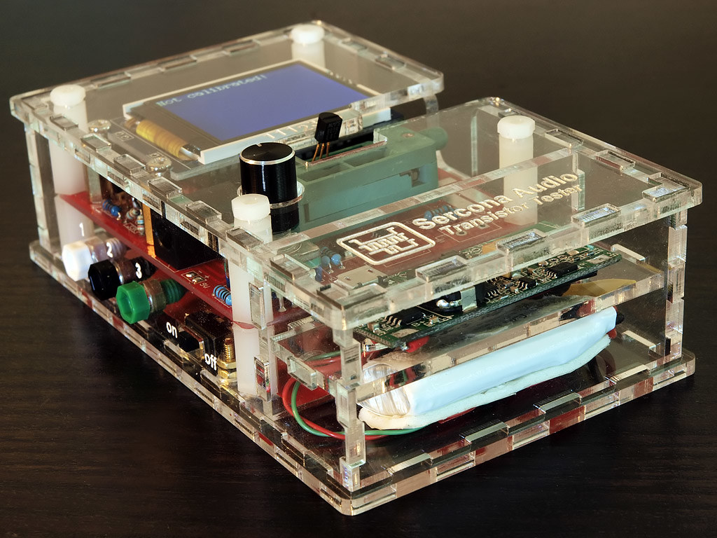
As far as I can tell from your pictures, you have a custom made enclosure (3d printed? nice BTW), possibly you are running wires from the PCB to the mini banana connectors and the tester is running on rechargeable battery with a step up converter....
My guess is that the extra wires and/or the converter are messing up the measurements on the new version (slightly different).
Try removing the wires to the mini banana connectors (on the PCB side) and power it with a 9V battery
Mauro
Hi.
Thanks for the possible indications of the problem, but I have three units of this tester and the evidence indicates that the causation could be another.
In the second tester I tested I did not have DC-DC converters, it is powered by a rechargeable Ni-Mh battery and has no bananas.
I have also tested putting the resistance in different combinations 1-2, 2-3, 1-3 and the result is the same.
Attached photos of him.
A greeting.
the rotary is not very useful, to be honest. on graphic displays, at least, the screen refresh time is too slow. up/down arrow buttons would be far superior to the rotary in THIS case.
I wouldn't say that. Monochrome displays don't really have that problem, and color displays can work slightly faster with an upgraded crystal. As for buttons in place of an encoder, IIRC firmware support for them is there. Just add them.
close-ups of my Qi wireless charger build:

I divided the battery area in half; top half has this board (charger and up-verter to convert 3.7v to 5v)
https://www.amazon.com/gp/product/B00WDPQ8CE/bottom half of the compartment is where I have a quadcopter battery, 500mah, 3.7v.
the Qi charging coil is this item (but there are MANY like it; this one is just typical):
https://www.amazon.com/gp/product/B0199NI5XWcut off the micro-usb plug, find which connections are plus and minus and then just wire to the pads on the small charger pcb. I removed the large usb port on the board since its not needed and just gets in the way; there are wires from that output to the place on the tester board that would get 5v from the regulator chip.
I recently bought one of these on eBay as a kit as it was slightly cheaper and I thought it'd be fun to assemble. I finished assembling it the other day and tested it and everything seemed to work fine. Measured a few inductors and capacitors and they all read within the specified precision. However, when I picked it up again today and turned it on I noticed some weird glitches on the screen (See attached). I don't think it's the screen or dry joints as it appears to effect the same portion of text each time. I'm thinking ESD issue with the microcontroller? I can't exactly just reprogram it as it came pre-programmed without the source code. I've tried disconnecting the battery for some time but upon reconnecting and turning it on again it has the same issue. I've ran the display test program which shows it can display all the characters just fine, so I don't think there's an issue with the display itself. Anyone got any ideas?
Reprogram it. The source code is open, and precompiled versions are freely available, too. Nobody knows what the Chinese "manufacturers" flash into these things and how they do it.
Reprogram it. The source code is open, and precompiled versions are freely available, too. Nobody knows what the Chinese "manufacturers" flash into these things and how they do it.
Any idea where I could get the source from? Also I'm assuming there's a bunch of different versions, as these come in various styles with different screens and features. I don't really want to brick it by flashing the wrong code only to have it not work with the hardware, and then not be able to find the original.
I've posted the links just one page back

You could of course also buy a spare Atmega CPU for a buck, that way you can keep the current (buggy) Chinese firmware.
Or ask the seller for a new one based on the corruption, sometimes they are very careful about their positive feedback...
I've posted the links just one page back
Thanks, how do I identify which version I have? It's got an ATMega 328P, LCD is a JLX12864G-378 and the only other number seems to be on the PCB '1982-HS' and 'K132571BSJH'
You could of course also buy a spare Atmega CPU for a buck, that way you can keep the current (buggy) Chinese firmware.
Or ask the seller for a new one based on the corruption, sometimes they are very careful about their positive feedback...
Yea good call. I'm not sure I can be bothered to wait for a new one to arrive from China, I'll just order a new one so I can keep the old one if it doesn't work. Oddly I don't seem to have any spare DIP packaged 328s in my parts drawers.
Thanks, how do I identify which version I have? It's got an ATMega 328P, LCD is a JLX12864G-378 and the only other number seems to be on the PCB '1982-HS' and 'K132571BSJH'
I'd guess it's a ST7565. A picture of the tester (not just of the display) would help.
Question, before I attempt to upgrade my firmware. How do I tell which of the two color displays I have? The display panel itsel has no markings that are visible, and the only chips visible are a 4050 and an adjustable regulator, no controller/driver to be seen, without possibly prying off the LCD and polarizer. I'm assuming it won't actually hurt anything to just try one, and if it doesn't work, change the config file and try the other.
My particular unit is one from KKmoon, got it through Amazon. It has the PWM output, frequency counter, and volt input. Works great except I have upgraded to a 16MHz crystal and while the resistor values are pretty spot on, all caps read 2x value and of course the output of the PWM is 2x what is selected - I pick 1MHz and my scope reads 2MHz. Exactly as expected. While I'm at it I figured I would try the latest firmware - I have some spare ATmegas328p's so I will leave the one it came with alone for now and burn a different one. I followed some links posted earlier in this thread and I'm pretty sure I have all the right options selected in the make and config files except for the LCD. The rest of my toolchain works, I've been messing around with ATTiny85's in addition to stock Arduinos and I was able to reset the fuses on the original chip to get it to boot under the 16MHz clock, just with the expected timing errors.
If no one identifies it from the description given, photos are helpful.
The most common color display used by clones is the ST7735 (128x160) or something compatible.
Bit of an update. I received the blank ATMega 328 today and programmed it with the precompiled st7565_kit firmware. Stuck it in the transistor tester and it turns on, the LED works and the display backlight comes on but it doesn't display any information. I tried the other st7565 versions from the repository, st765, T5_st7565 and T3_T4_st7565 but they all had pretty much the same result. After sticking the original factory programmed IC back in it still works, albeit with the corrupted display data. Anyone got any ideas?
