Are you careful to fully discharge large capacitors before trying to test them?
Yes, all caps are properly discharged.
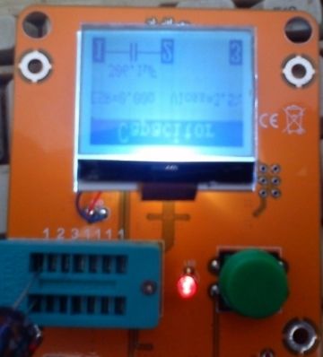
It looks to me like a firmware / LCD screen compatibility issue. Any suggestions ?
The screen looks like this :
I'd suggest beefing up the supply decoupling as these boards seem to have minimal amounts, try a 10uF on the regulator output as a starting point and additional 100n's as close as you reasonably can to the chip.
Hi to all ! did anybody of you try to add a Rotary encoder to one of the chinese clones with a graphical display ? I tried a Rotary switch with my homemade tester with M-firmware and a 2*16 line display , it worked fine. When I tried the chinese clone with graphic display (the one from EZM electronics and discrete components) I didn't succeed, I tried a lot of combinations of PD1,PD2 and PD3 inputs of the atmega328. Maybe somebody has an idea ?? Robert.
ps : I changed the 680R/470K resistors for the 0.1% types and also replaced the voltage regulator for a mcp1702-5002 and I got an accuracy of 0.1% back when measuring a precision resistor
Hello,
I bought this one on eBay. The software version is 1.11. I've got the documentation on the website of the developpers but I don't find what exactly are the information displayed for transistors: what are IC0 and ICs?
Thanks
Denis
In the annex is backup original firmware of my tester (v2.1)
Thank you very mch! How did you get it?
What about this one:
http://m.ebay.com/itm/251791049879?nav=SEARCH
Any comments?
Feel free for a little look inside here:
http://www.mikrocontroller.net/topic/248078?page=7#4086662FW from 15.04.2015:
http://www.mikrocontroller.net/topic/248078?page=7#4092967When I tried the chinese clone with graphic display (the one from EZM electronics and discrete components) I didn't succeed, I tried a lot of combinations of PD1,PD2 and PD3 inputs of the atmega328.
I do not know EZM, only Fish and new LiIon, but the rotary must be activated in the makefile.
IMHO you need a special compiled version of your own, no standard-hex.
In some makefiles the rotary is pre activated.
I changed the 680R/470K resistors for the 0.1% types and also replaced the voltage regulator for a mcp1702-5002 and I got an accuracy of 0.1% back when measuring a precision resistor
.1% resistors are no bad idea but the LDO alone isn't the hack... you need to offer an external voltage reference.
My choose was a LT1009C, it's precision is 0.2%. So the overall prec should be better than 0.5%.
Thanks Shock,
With BJT transistors the device indicates ICE0 and ICEs (forgot the ´E' in my previous post). Those values are most of the time 0.00mA with small signls transistors, and non zero for power transistors. Probably collector-emitter currents, but in which conditions? There are also the current gain hFE and a voltage Uf (base-emitter).
For MOS and FET, the device indicates only two voltages: Vt and Uf and a capacity.
The user manual explains very well the measurement principles, but not the results.
Denis
Excellent document Shock, I appreciate.
ICEo (not ICE0) and ICEs are then leakage currents under reverse voltages. I found also this document from the device's developpers.
This device is really impressive!
Denis
.1% resistors are no bad idea but the LDO alone isn't the hack... you need to offer an external voltage reference.
My choose was a LT1009C, it's precision is 0.2%. So the overall prec should be better than 0.5%.
Having said that, it's worth just checking the accuracy of the cheapo TL431 reference on the board (if fitted) before swapping it - the one on mine reads a nice stable 2.501V

I'm debating on getting one of the Chinese "GM328 fish clone" testers.
Anyone know where I could land an unpopulated PCB so that I can use my own precision components?
Still be more economical to buy one and remove parts you dont want.
Anyone know where I could land an unpopulated PCB so that I can use my own precision components?
There are several PCB layouts in the forum at
http://www.mikrocontroller.net/topic/248078 (mostly German) and from time to time someone organizes an aggregated order. But I haven't seen any shop selling bare PCBs yet. You can also find two PCBs in the firmware repo for DYI-ing (one is veroboard based, and the other one is for through-hole parts). There's also an rotary encoder / frequency counter adapter for character LCDs.
Hi - I just found this thread due to the Hackaday post.
Great little tool!
Wifey won't like it, but I think I'll build one this weekend. I don't have the requisite 0.1% 680R and 470K resistors, but I am certain I will find some relatively easily by measuring and sorting my 1% resistors.
I have all the other parts in my lab, and I ordered two 128x64 LCD's for later builds.
I downloaded the tarball, and I am now reading the v1.12k manual.
A big thank you to Markus and Karl-Heinz for your work on this.
Bill
---
http://Mikronauts.com
For owners of this tester which is offered on ebay under the designation as "LCR-T3" or "LCR-T4 Transistor Tester" I offer a way to update firmware. Devices have identical G-LCD (ST7565), but slightly different PCB. Update works on both versions of this tester. However, attention should be given to the fact that the ISP connector from the parts is mirrored. For this purpose I have pieced together a simple detachable
adapter enabling the MCU to program without arranging the auxiliary ISP connector (see attached pictures). Many thanks to Roland Elmiger (hb9gaa) from the official discussion forum for providing
the schematic diagram.
I found this one GM328A firmware V1.12 with input port protection and 0.1% resistors. Menu has Transistor, Frequency, f-Generator,10-bit PWM, C=ESR@TP1:3, rotary encoder, Self Test, Contrast, Show Data, Switch Off
U3 (V05) & D1 (KK 1450) may be similar to the protect circuit attached. Voltage regulators, 5V (AMS1117-5.0) & 3V3 (AMS1117-3.3) for LCD, U4 voltage reference TL431
http://www.ebay.com.au/itm/Latest-12864-LCD-Transistor-Tester-Capacitance-ESR-Meter-LCR-GM328A-Test-Clip-/321735790147?pt=LH_DefaultDomain_0&hash=item4ae8f28e43http://www.ebay.com.au/itm/311343672563?edit: added photo of component side of PCB.
I thinking of getting the LCR-T3 above, can anyone confirm if has frequency generator too?
After updating the software (currently v1.12k) and extensions the hardware (see the official manual) will work:
- measurement of zener voltage above 4 Volt
- measure the voltage to 50V
- frequency generator
- frequency measurement
- 10-bit PWM
- using of a rotary pulse encoder with a push button for easier control of the menu function.
Thanks Tom666, I go ahead and get one, seem to be the best version, 6 pin ISP, external voltage reference, components all clearly marked with values, smd, compact design single pcb, no hardware faults (unlike fish). Latest firmware.
edit: After seeing component side of GM328, I bought the GM328 as it has protection and all same features above.
Since we're talking about the function generator (squarewave), would you be interested in a sinusodial signal too? I haven't looked into the details yet, but I think it would be possible with the help of an external low-pass filter (2 components) attached to the probe pins temporarily. I can't say anything about the frequency range yet, but it would be far less than the squarewave. BTW, what do you think about the squarewave generator (requires a rotary encoder) of the m-firmware? Is the user interface ok? Haven't got any feedback about that so far.
I'd rather like to see a new reference design of the board that incorporates all features, e.g. encoder, zener and generator into it in a modular way.
I started to do such a design but due to time constraints didn't get any further than the attached schematic (which is missing the relay and diode input protection feature).
The sinusoidal wave gen would be okay to have, but I had no use-case so far.
Is this a true function generator capable of at the very minimum triangle or is this just square wave?
Thanks. Although unable to get latest versions working I am very happy with the original firmware and greatly appreciate the effort you put into this. But a little disappointed to see the term "function generator" used here which at the least would generally include triangle or sine.. This kind of stretching might be expected from Ebay chinese liars but IMO better to refer to it as "square wave generator" or "signal generator" to not get peoples hopes up. Anyway, thanks again for the wonderful design. It proved to be an invaluable tool here.