Certainly going headless, button-less and USB-OTG seems a good conversation to start, but maybe not here in a support thread.
I don't think I'm qualified to start a thread on it, but surely others might weigh-in on the merits (but I like your BT idea..)

Hi guys!
I'm looking to buy one of these testers but there is so much stuff on eBay that I don't know what to choose.
Can you recommend me the best one?
Thank you!
Yes, that appears to be an AY-AT.
Just bought one of these from AliExpress. How much Russian text should there be? I have quite a lot of text in Russian, although the test output is in English.
Continuing from
this post, the st7735 is getting powered from two sources.

Can I replace 3v3_z14 zener with a 1/2w watt resistor? But I dont know the current consumption of pin 10+11. Could not find it in the datasheet.
----------------
I looked at the schematic posted
here. There are two types of st7735 - a readymade version with male headers and the bare lcd version(found in fish8840tft) which is cheaper to buy from aliexp. The person who made this schematic has used the first version and using an LDO(ams1117 3.3v). He/she has also added a few higher value capacitors(marked in red).
Hello, first post here. Apologize for bad english
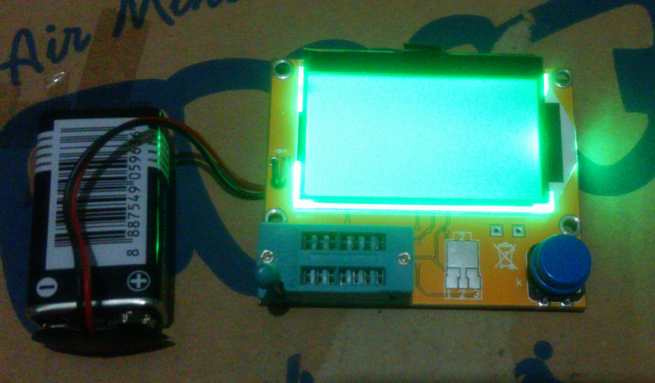
My bro give me this
this. T4, right?
The problem is :
- tester give the wrong voltage. I mean, too much voltage drop. In my cheap multimeter, bat 9.6v. In this tester, around 7.8v
- this is im not sure, because i cant compare. Tester give wrong pin for jfet. Sometimes detect as npn
What i did
- selftest, jumper 3 pin in zif socket + 220n after that
still problem.
what i must do then?
the closest search, give me
tom666 post. I think, still have arduino uno. Its right?
or any other option for the latest firmware?
what the right? its hard to learn how to flash to that?
notes : Me are noob in electronic.
Big Thanks.
Febri
Can I replace 3v3_z14 zener with a 1/2w watt resistor? But I dont know the current consumption of pin 10+11. Could not find it in the datasheet.
This would be a bad idea since the LCD isn't a constant load. The current consumption changes with the operation mode and a few settings. A zener or LDO is the right way.
T4, right?
Yep!
what i must do then?
the closest search, give me tom666 post. I think, still have arduino uno. Its right?
Yes, you can use an Arduino as programmer.
or any other option for the latest firmware? what the right? its hard to learn how to flash to that?
k-firmware: mega328_T3_T4_st7565 or mega328_T4_v2_st7565
m-firmware: see Clones file for settings for the T3/T4 clone and compile the firmware (Software/Markus)
You'll find tons of guides about programming an ATmega MCU in the internet. There are also a few guides in this thread.
Can I replace 3v3_z14 zener with a 1/2w watt resistor? But I dont know the current consumption of pin 10+11. Could not find it in the datasheet.
This would be a bad idea since the LCD isn't a constant load. The current consumption changes with the operation mode and a few settings. A zener or LDO is the right way.
Understood
-----
I made the schematic of fish8840tft(using
this post) + mt3608 module. Im attaching the files(altium) if anyone is interested in poking around. Kindly correct mistakes if any.
edit 14 july
fish.zip = fish8840 + mt3608 (smd 328p)
karl.zip = karl heinz kubbeler 1.13k + mt3608 + st7735 (dip 328p)
note: resistors are in standing position
Hello everyone,
I have an old transistor tester that has the 3 screw type connector. Is there anyone that know if a adapter board exists for me to install a zif socket instead for the 3 hole screw type connector?
Thank you to all!
Help please!
I have an AY-AT 328 tester (Supposedly the Bees Knees at the moment) and it’s almost built, but I’m in need of some info on the small 6 legged device that is an SMD and is situated with the other 2 SMDs at the bottom of the board and is marked with MC5 on the top of it. It is between the left blue 2way Connector Block and the Clamping Tester Block (Sorry, don’t have the name to hand).
Any help would be much appreciated. Many thanks anyway.
John
rddube
Hello everyone,
I have an old transistor tester that has the 3 screw type connector. Is there anyone that know if a adapter board exists for me to install a zif socket instead for the 3 hole screw type connector?
Thank you to all!
Hi
I wouldn't have thought that you would have the space anywhere on the board to fit one. Another way would be to fit speaker clamp connectors as they are smaller. Hope that helps.
Yah the space is there...all I would need is a daugtherboard to take a 14 pin connector down to 3 .........must exist?
Help please!
I have an AY-AT 328 tester (Supposedly the Bees Knees at the moment) and it’s almost built, but I’m in need of some info on the small 6 legged device that is an SMD and is situated with the other 2 SMDs at the bottom of the board and is marked with MC5 on the top of it. It is between the left blue 2way Connector Block and the Clamping Tester Block (Sorry, don’t have the name to hand).
Any help would be much appreciated. Many thanks anyway.
John
The SVR05-4 is a TVS diode array and used as part of a protection circuit. See:
http://m.littelfuse.com/~/media/electronics/datasheets/tvs_diode_arrays/littelfuse_tvs_diode_array_srv05_datasheet.pdf.pdf
The ZIF socket wiring just shorts some of the pins together as shown in the various circuits posted.
You could just solder the ZIF to some vero or perf board for mounting and then wire the pins together (as per the circuits) and solder the 3 wires to take back to your tester.
Continuing from this post, the st7735 is getting powered from two sources.
Can I replace 3v3_z14 zener with a 1/2w watt resistor? But I dont know the current consumption of pin 10+11. Could not find it in the datasheet.
----------------
I looked at the schematic posted here. There are two types of st7735 - a readymade version with male headers and the bare lcd version(found in fish8840tft) which is cheaper to buy from aliexp. The person who made this schematic has used the first version and using an LDO(ams1117 3.3v). He/she has also added a few higher value capacitors(marked in red).
I think the circuit drawing you inserted is not correct. Based on the pinouts and there being no current limiting resistor as part of the voltage divider (together with the Zener) for the 3.3V supply it is unlikely to be a Zener but more likely a 3.3V LDO regulator (like the amd1117 3.3v you mentioned later). You can't replace it (even if it is drawn out correctly) with a resistor.
Help please!
I have an AY-AT 328 tester (Supposedly the Bees Knees at the moment) and it’s almost built, but I’m in need of some info on the small 6 legged device that is an SMD and is situated with the other 2 SMDs at the bottom of the board and is marked with MC5 on the top of it. It is between the left blue 2way Connector Block and the Clamping Tester Block (Sorry, don’t have the name to hand).
Any help would be much appreciated. Many thanks anyway.
John
The SVR05-4 is a TVS diode array and used as part of a protection circuit. See:
http://m.littelfuse.com/~/media/electronics/datasheets/tvs_diode_arrays/littelfuse_tvs_diode_array_srv05_datasheet.pdf.pdf
Thanks for the info, it was in front of my eyes all the time, thought that number was something else to do with the board but there you go. I'd have never got it as I'd already dismissed it previously. Your help is much appreciated.
Hello,
Special thanks to madires and tom666, i can flash some friend tester

sorry, too excited, eureka moment noob. hehe.
but,
1 tester, T4 no strip grid, have blank lcd after flashing

backlight still on, but no output
somehow, in W10, success if add \
REM Writing Flash + EEPROM + Fuses (L=F7, H=D9, E=04)
avrdude -c avrisp -p m328p -P COM4 -b 19200 -e -U flash:w:"TransistorTester.hex":a -U eeprom:w:"TransistorTester.eep":a \-U lfuse:w:0xF7:m \-U hfuse:w:0xD9:m \-U efuse:w:0x04:m
below output from cmd. Run on W10
Microsoft Windows [Version 10.0.17134.165]
(c) 2018 Microsoft Corporation. All rights reserved.

C:\Users\hore>cd C:\Users\hore\Downloads\Anto\LCR-Tx_v1.12k_r508_EN

C:\Users\hore\Downloads\Anto\LCR-Tx_v1.12k_r508_EN>FlashK.bat

C:\Users\hore\Downloads\Anto\LCR-Tx_v1.12k_r508_EN>REM Writing Flash + EEPROM + Fuses (L=F7, H=D9, E=04)

C:\Users\hore\Downloads\Anto\LCR-Tx_v1.12k_r508_EN>avrdude -c avrisp -p m328p -P COM4 -b 19200 -e -U flash:w:"TransistorTester.hex":a -U eeprom:w:"TransistorTester.eep":a \-U lfuse:w:0xF7:m \-U hfuse:w:0xD9:m \-U efuse:w:0x04:m
avrdude: ser_open(): can't set com-state for "\\.\COM4"

avrdude done.  Thank you.


C:\Users\hore\Downloads\Anto\LCR-Tx_v1.12k_r508_EN>FlashK.bat

C:\Users\hore\Downloads\Anto\LCR-Tx_v1.12k_r508_EN>REM Writing Flash + EEPROM + Fuses (L=F7, H=D9, E=04)

C:\Users\hore\Downloads\Anto\LCR-Tx_v1.12k_r508_EN>avrdude -c avrisp -p m328p -P COM4 -b 19200 -e -U flash:w:"TransistorTester.hex":a -U eeprom:w:"TransistorTester.eep":a \-U lfuse:w:0xF7:m \-U hfuse:w:0xD9:m \-U efuse:w:0x04:m

avrdude: AVR device initialized and ready to accept instructions

Reading | ################################################## | 100% 0.03s

avrdude: Device signature = 0x1e950f (probably m328p)
avrdude: erasing chip
avrdude: reading input file "TransistorTester.hex"
avrdude: input file TransistorTester.hex auto detected as Intel Hex
avrdude: writing flash (28872 bytes):

Writing | ################################################## | 100% 32.25s

avrdude: 28872 bytes of flash written
avrdude: verifying flash memory against TransistorTester.hex:
avrdude: load data flash data from input file TransistorTester.hex:
avrdude: input file TransistorTester.hex auto detected as Intel Hex
avrdude: input file TransistorTester.hex contains 28872 bytes
avrdude: reading on-chip flash data:

Reading | ################################################## | 100% 18.39s

avrdude: verifying ...
avrdude: 28872 bytes of flash verified
avrdude: reading input file "TransistorTester.eep"
avrdude: input file TransistorTester.eep auto detected as Intel Hex
avrdude: writing eeprom (15 bytes):

Writing | ################################################## | 100% 0.80s

avrdude: 15 bytes of eeprom written
avrdude: verifying eeprom memory against TransistorTester.eep:
avrdude: load data eeprom data from input file TransistorTester.eep:
avrdude: input file TransistorTester.eep auto detected as Intel Hex
avrdude: input file TransistorTester.eep contains 15 bytes
avrdude: reading on-chip eeprom data:

Reading | ################################################## | 100% 0.08s

avrdude: verifying ...
avrdude: 15 bytes of eeprom verified

avrdude: safemode: Fuses OK (E:FC, H:D9, L:F7)

avrdude done.  Thank you.

C:\Users\hore\Downloads\Anto\LCR-Tx_v1.12k_r508_EN>
Didnt compare that output with successfull flash
So, what happen? trouble with lcd? on what? and how to fix?
Big Thanks
avrdude: reading input file "TransistorTester.eep"
avrdude: input file TransistorTester.eep auto detected as Intel Hex
avrdude: writing eeprom (15 bytes):
That should be much more (about 700 -1000 bytes).
That should be much more (about 700 -1000 bytes).
Did flash some friend T4 (strip) and my T4 (no strip).
cmd output :
Microsoft Windows [Version 10.0.17134.165]
(c) 2018 Microsoft Corporation. All rights reserved.

C:\Users\hore>cd C:\Users\hore\Downloads\Anto\FF

C:\Users\hore\Downloads\Anto\FF>FlashK.bat

C:\Users\hore\Downloads\Anto\FF>REM Writing Flash + EEPROM + Fuses (L=F7, H=D9, E=04)

C:\Users\hore\Downloads\Anto\FF>avrdude -c avrisp -p m328p -P COM4 -b 19200 -e -U flash:w:"TransistorTester.hex":a -U eeprom:w:"TransistorTester.eep":a \-U lfuse:w:0xF7:m \-U hfuse:w:0xD9:m \-U efuse:w:0x04:m

avrdude: AVR device initialized and ready to accept instructions

Reading | ################################################## | 100% 0.03s

avrdude: Device signature = 0x000000 (retrying)

Reading | ################################################## | 100% 0.03s

avrdude: Device signature = 0x000000 (retrying)

Reading | ################################################## | 100% 0.03s

avrdude: Device signature = 0x000000
avrdude: Yikes!  Invalid device signature.
         Double check connections and try again, or use -F to override
         this check.


avrdude done.  Thank you.


C:\Users\hore\Downloads\Anto\FF>FlashK.bat

C:\Users\hore\Downloads\Anto\FF>REM Writing Flash + EEPROM + Fuses (L=F7, H=D9, E=04)

C:\Users\hore\Downloads\Anto\FF>avrdude -c avrisp -p m328p -P COM4 -b 19200 -e -U flash:w:"TransistorTester.hex":a -U eeprom:w:"TransistorTester.eep":a \-U lfuse:w:0xF7:m \-U hfuse:w:0xD9:m \-U efuse:w:0x04:m

avrdude: AVR device initialized and ready to accept instructions

Reading | ################################################## | 100% 0.03s

avrdude: Device signature = 0x1e950f (probably m328p)
avrdude: erasing chip
avrdude: reading input file "TransistorTester.hex"
avrdude: input file TransistorTester.hex auto detected as Intel Hex
avrdude: writing flash (31016 bytes):

Writing | ################################################## | 100% 34.64s

avrdude: 31016 bytes of flash written
avrdude: verifying flash memory against TransistorTester.hex:
avrdude: load data flash data from input file TransistorTester.hex:
avrdude: input file TransistorTester.hex auto detected as Intel Hex
avrdude: input file TransistorTester.hex contains 31016 bytes
avrdude: reading on-chip flash data:

Reading | ################################################## | 100% 19.70s

avrdude: verifying ...
avrdude: 31016 bytes of flash verified
avrdude: reading input file "TransistorTester.eep"
avrdude: input file TransistorTester.eep auto detected as Intel Hex
avrdude: writing eeprom (881 bytes):

Writing | ################################################## | 100% 43.34s

avrdude: 881 bytes of eeprom written
avrdude: verifying eeprom memory against TransistorTester.eep:
avrdude: load data eeprom data from input file TransistorTester.eep:
avrdude: input file TransistorTester.eep auto detected as Intel Hex
avrdude: input file TransistorTester.eep contains 881 bytes
avrdude: reading on-chip eeprom data:

Reading | ################################################## | 100% 3.52s

avrdude: verifying ...
avrdude: 881 bytes of eeprom verified

avrdude: safemode: Fuses OK (E:FC, H:D9, L:F7)

avrdude done.  Thank you.


C:\Users\hore\Downloads\Anto\FF>
Friend T4, success
My T4, still no output in LCD. I think broken connection or something. Just Led ON only.
since i dont know how to repair this lcd, and more cheap to buy, i go latest option
What you suggest? T4 again or what?
Massive Thanks
MGB
change the default contrast.
i have seen what looked like a dead unit that just had VERY low contrast.
change the default contrast.
how? i just know how to connect cable and click flash only, Sir
the patient :